2
$&2867,&&21),*85$7,2167$1'$5'67&2035(66256,168/$7,216&
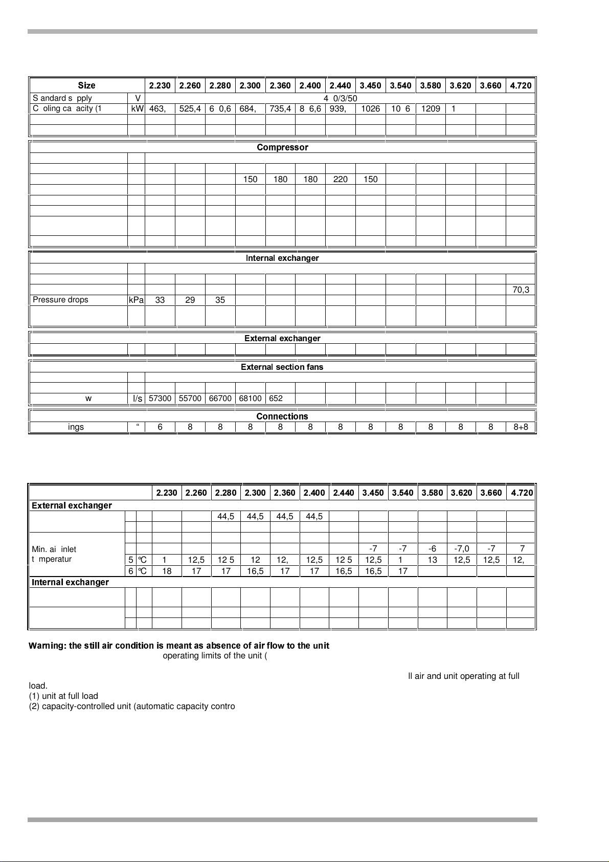
*(1(5$/7(&+1,&$/'$7$
Standard supply V
400/3/50
Cooling capacity (1) kW
463,6
525,4
600,6
684,3
735,4
846,6
939,5
1026 1096 1209 1303 1395 1471
Compressor input kW
163,4
190,1
213,2
237,4
277,0
301,7
330,1
351,9
409,5
423,4
467,6
491,8
554,1
Total input power kW
184,5
213,2
239,2
266,5
307,1
337,3
366 398 459,7
477 526,8
558,9
614,1
Compressor type single screw
Compressors No. Nr
2 2 2 2 2 2 2 3 3 3 3 3 4
Nominal power (C1)
HP
100 130 130 150 180 180 220 150 180 180 180 220 180
Nominal power (C2) HP
130 130 150 150 180 220 220 150 180 180 220 220 180
Nominal power (C3) HP
- - - - - - - 150 180 220 220 220 180
Nominal power (C4) HP
- - - - - - - - - - - - 180
Capacity control steps
STD Nr
6 6 6 6 6 6 6 9 9 9 9 9 12
Refrigerant circuits Nr
2 2 2 2 2 2 2 3 3 3 3 3 4
!"$#%!&'(#*)+,&!-#%
Type Tube bundle
Number Nr
1 1 1 1 1 1 1 1 1 1 1 1 2
Water flow l/s
22,1 25,1 28,7 32,7 35,1 40,4 44,9 49,0 52,4 57,8 62,3 66,7 70,3
Pressure drops kPa
33 29 35 40 46 66 48 56 76 66 88 100 47
Water content l 114 222 206 206 184 222 252 252 295 462 423 423 184+
184
.)"$#%!&'*#()+,&!-#%
Front surface m2
24 24 29,4 29,4 29,4 35 35 43,4 43,4 48 53 54 58,8
.)"/#%!&'(0#+("1 23!54/&!0
Fan type axial
Fan No. Nr
9 10 11 12 12 13 14 18 18 20 20 22 24
STD water flow l/s
57300
55700
66700
68100
65200
83350
87350
102000
102000
112750
120000
132000
134800
66789 6
Water fittings “ 6 8 8 8 8 8 8 8 8 8 8 8 8+8
(1) data referred to the following conditions: internal exchanger water = 12/7°C
room temperature = 35°C
23(5$7,21/,0,76&22/,1*
6L]H
:3;
8<=6>?
;
7@>6A
1
°C 44,5 44,5 44,5 44,5 44,5 44,5 44,5 44,5 44,5 44,5 44,5 44,5 44,5
Max. air inlet
temperature 2
°C 47,5 48 48 48 48 47,5 47,5 48 48 48 48,0 47,5 48
3
°C -10 -10 -10 -10 -10 -10 -10 -10 -10 -10 -10,0
-10 -10
4
°C -5 -6 -6 -7 -7 -8 -8 -7 -7 -6 -7,0 -7 -7
5
°C 14 12,5 12,5 12 12,5 12,5 12,5 12,5 13 13 12,5 12,5 12,5
Min. air inlet
temperature
6
°C 18 17 17 16,5 17 17 16,5 16,5 17 17,5 17,5 16,5 17
B
68<=6>?
;
7@>6A
Max water inlet
temperature 7
°C
21 21 21 21 21 21 21 21 21 21 21 21 21
8
°C 6 6 6 6 6 6 6 6 6 6 6 6 6
Min water outlet
temperature 9
°C -8 -8 -8 -8 -8 -8 -8 -8 -8 -8 -8 -8 -8
Note: In any case, the unit should never be exposed to or operated, transported and/or stored at temperatures below -10°C.
C
>D63E6AGF8D@H8DE?E?>EI76J 89 6K LM>68>N>O67NP>EP9? QR8L8D@MS63 8
. Any wind condition can let air pass through the
condenser coil thus worsening the operating limits of the unit (see limits with air speed at 0,5 m/s & 1 m/s). In order to avoid such
situation, windbreak barriers are necessary. The minimum ambient temperature is given for units equipped with low ambient control
or with ECObreeze fans.For standard unit without these options, this value is of about 18°C with still air and unit operating at full
load.
(1) unit at full load
(2) capacity-controlled unit (automatic capacity control)
(3) unit at full load external exchanger air in quiet
(4) capacity-controlled unit (automatic capacity control) external exchanger air in quiet
(5) capacity-controlled unit (automatic capacity control) air to external exchanger = 0.5m/sec
(6) capacity-controlled unit (automatic capacity control) external exchanger air = 1m/sec
(7) external exchanger air intake 35°C
(8) Standard Version external exchanger air intake 35°C
(9) Low temperature version external exchanger air intake 35°C
Fluid with ethylene glycol of 40%


