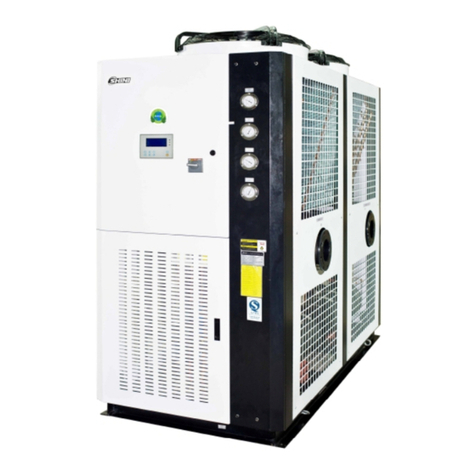
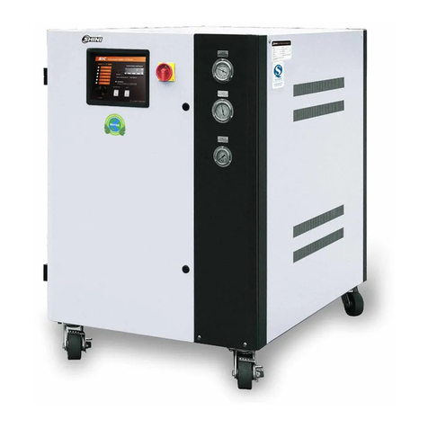
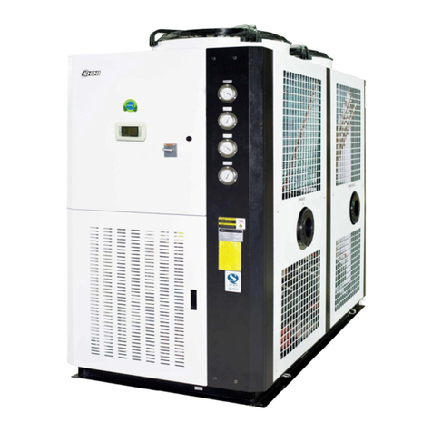
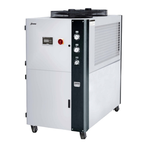
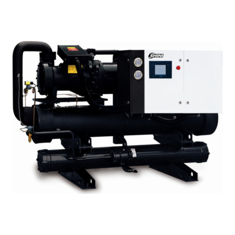
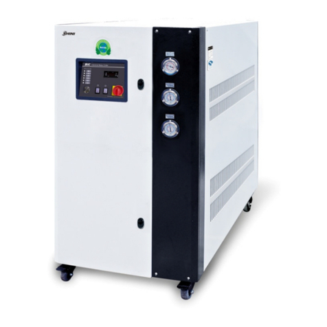
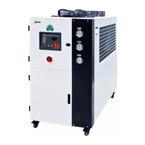
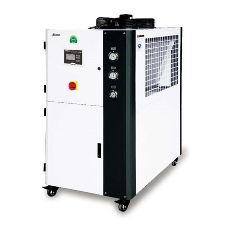
Shini SIC-W Series User manual

SIC-W
Water-cooled Water Chillers
Date: Mar., 2022
Version: Ver.D (English)


3(42)
Contents
1. General Description ........................................................................................6
1.1 Coding Principle......................................................................................7
1.2 Features..................................................................................................7
1.3 Technical Specifications .........................................................................9
1.3.1 External Dimensions ......................................................................9
1.3.1 Specification List.........................................................................11
1.4 Safety Regulations................................................................................13
1.4.1 Security Labels...........................................................................13
1.5 Exemption Clause.................................................................................14
2. Structural Features and Working Principle.................................................15
2.1 Main Functions......................................................................................15
2.1.1 Working Principle........................................................................15
2.2 Main Components and Functions .........................................................17
2.2.1 Compressor................................................................................17
2.2.2 Condenser..................................................................................17
2.2.3 Drying Filter................................................................................17
2.2.4 Thermal Expansion Valve...........................................................18
2.2.5 Evaporator..................................................................................18
2.2.6 High and Low Pressure Controller..............................................19
2.3 Options .................................................................................................19
2.3.1 Refrigerant Indicator...................................................................19
2.3.2 Liquid Pipe Solenoid Valve.........................................................19
2.3.3 Hot-gas Bypass Valve................................................................20
2.3.4 Flow Switch ................................................................................20
2.3.5 Liquid Level Indicator..................................................................20
2.4 Main Electrical Components.................................................................22
2.4.1 Thermal Overload Relay.............................................................22
3. Installation and Debugging........................................................................... 23
3.1 Installation Notices................................................................................23
3.2 Installation Diagram..............................................................................25
3.3 Power Connection.................................................................................25

4(42)
4. Application and Operation............................................................................26
4.1 Panel Diagram......................................................................................26
4.2 Common Screens.................................................................................26
4.3 Quick Operation....................................................................................27
4.4 Startup..................................................................................................28
4.5 Shutdown..............................................................................................28
4.6 User Menu............................................................................................29
4.6.1 Parameter Operation..................................................................29
4.6.2 User Setting................................................................................29
4.6.3 Machine Set ...............................................................................30
4.6.4 System Time Set........................................................................30
5. Trouble-shooting...........................................................................................31
6. Repair and Maintenance ...............................................................................35
6.1 Filling the Refrigerant............................................................................38
6.2 Components Maintenance....................................................................39
6.2.1 Condenser..................................................................................39
6.2.2 Evaporator..................................................................................40
6.3 Maintenance Schedule .........................................................................41
6.3.1 About the Machine......................................................................41
6.3.2 Check after Installation...............................................................41
6.3.3 Daily Checking ...........................................................................41
6.3.4 Weekly Checking........................................................................41
6.3.5 Montly Checking...........................................................................41
6.3.6 Trimonthly Checking...................................................................42
6.3.7 Half-yearly Checking ..................................................................42
6.3.8 Yearly Checking .........................................................................42
6.3.9 3 year Checking .........................................................................42
Table Index
Table 1-1: Specifications List (1)......................................................................... 9
Table 1-2: Specifications List (2)....................................................................... 10
Table 1-3 Specification List (1) ....................................................................... 11

5(42)
Table 1-4 Specifications List (2)...................................................................... 12
Table 6-1 SIC-W Series Filling Quantity ......................................................... 38
Picture Index
Picture 1-1: Outline Dimensional Drawing........................................................... 9
Picture 2-1 Working Principle Diagram........................................................... 15
Picture 2-2 Compressor.................................................................................. 17
Picture 2-3 Condenser.................................................................................... 17
Picture 2-4 Drying Filter.................................................................................. 18
Picture 2-5 Thermal Expansion Valve............................................................. 18
Picture 2-6 Evaporator.................................................................................... 19
Picture 2-7 High and Low Pressure Controller................................................ 19
Picture 2-8 Refrigerant Indicator..................................................................... 19
Picture 2-9 Liquid Pipe Solenoid Valve........................................................... 20
Picture 2-10 Hot-gas By-pass Valve............................................................... 20
Picture 2-11 Flow Switch ................................................................................ 20
Picture 2-12 Liquid Level Indicator.................................................................. 21
Picture 2-13 Thermal Overlaod Relay............................................................. 22
Picture 3-1 Machine Installation Location ....................................................... 25
Picture 6-1 Fill in the Refrigerant (1)............................................................... 38
Picture 6-2 Fill in the Refrigerant (2)............................................................... 38
Picture 6-3 Water Drainage Port..................................................................... 40

6(42)
1. General Description
Please read through this operation manual before using and installation to
avoid damage of the machine and personal injuries.
SIC-W series water-cooled chiller adopts single-stage vapour compressed circuit,
with compressor overload protection, pump overload protection, phase reverse
alarm, anti-freezing protection, high & low pressure protector, which features
stable performance and long service life. It can quickly cool down, and maintain
stable temperature to meet the requirements of customers. This series of products
work following the heating and cooling exchange principle, which is an
indispensable device for cooling applications in modern industry.
Model SIC-5W

7(42)
1.1 Coding Principle
1.2 Features
Standard configuration
Cooling range 7~35
Stainless steel insulated water tank and evaporator
Anti-freezing protector
Adopt R22 refrigerant, and cooling effect
The refrigeration system adopts high and lower pressure controller for
protection
Low pressure pumps are standard configurations.
Compressor and pump both have overload protector.
Adopt Italian temperature controller that can maintain the accuracy of
0.1℃.
All adopt branded compressors with low noise, high efficiency and long
service life.
SIC-W adopts fin style condenser design without any need of cooling water
for excellent heat transfer and rapid cooling.
Accessory option
Medium and high pressure pumps are optional to meet different water
pressure requirements.
Water tank level sensor is optional to check whether the water level is in
normal condition.
Hot-gas bypass valve is optional that can maintain the temperature control
accuracy up to ±1℃;
SIC-3W-5W can choose 1 / 2 "4-in 4-out water flow regulator
The liquid pipe solenoid valve is optional to prevent evaporator freezing by

8(42)
cutting the refrigerant immediately after downtime.
Refrigerant indicator can be opted to detect the refrigerant and ensure its
quality and water ratio.
Optional flow switches to detect the chilled water flow.
All service work should be carried out by a person with technical training or
corresponding professional experience. The manual contains instructions for both
handling and servicing. Chapter 6, which contains service instructions intended for
service engineers. Other chapters contain instructions for the daily operator.
Any modifications of the machine must be approved by SHINI in order to avoid
personal injury and damage to machine. We shall not be liable for any damage
caused by unauthorized change of the machine.
Our company provides excellent after-sales service. Should you have any problem
during using the machine, please contact the company or the local vendor.
Shini Hotline Service:
Headquarter and Taipei factory
Tel: + 886 (0)2 2680 9119
Shini Plastics Technologies (Dongguan), Inc.
Tel: +86 (0)769 8331 3588
Shini Plastics Technologies (Pinghu), Inc.
Tel: +86 (0)573 8522 5288
Shinden Precision Machinery (Chongqing), Inc.:
+86 (0)23 6431 0898

9(42)
1.3 Technical Specifications
1.3.1 External Dimensions
Picture 1-1: Outline Dimensional Drawing
Table 1-1: Specifications List (1)
Model SIC-3W SIC-5W SIC-8W SIC-10W
SIC-12.5W
SIC-15W
H(mm) 970 970 1050 1050 1200 1200
H1(mm) 790 790 910 910 1078 1078
H2(mm) 91 91 140 140 140 140
H3(mm) 207 207 225 225 308 308
W(mm) 550 550 830 830 865 865
W1(mm) 273 273 370 370 459 459
W2(mm) 164 164 230 230 202 202
W3(mm) 164 164 230 230 162 162
D(mm) 1080 1080 1200 1200 1470 1470
P1 cooling water inlet
(inch) 1 11/2 11/2 2 2 21/2
P2 cooling water outlet
(inch) 1 11/2 11/2 2 2 21/2
P3 freezing water inlet
(inch) 1 1 11/2 11/2 2 2
P4 freezing water outlet
(inch) 1 1 11/2 11/2 2 2
P5
water tank outlet (inch)
11/2 11/2 11/2 11/2 11/2 11/2
P6 water tank overflow
port (inch) 11/2 11/2 11/2 11/2 11/2 11/2
Weight(kg) 230 290 400 410 610 640

10(42)
Table 1-2: Specifications List (2)
Model SIC-20W SIC-25W SIC-30W SIC-40W SIC-45W SIC-50W
H(mm) 1450 1450 1450 1760 1760 1760
H1(mm) 765 765 765 910 1078 170
H2(mm) 200 200 200 140 140 120
H3(mm) 190 190 200 190 190 190
W(mm) 1055 1055 1055 1100 1100 1100
W1(mm) 300 300 300 370 459 180
W2(mm) 295 295 215 229 202 325
W3(mm) 205 205 205 230 162 505
D(mm) 2235 2235 2235 2870 2870 3285
P1 cooling water inlet
(inch) 21/2 21/221/2 21/2 21/2 21/2 21/2
P2 cooling water
outlet (inch) 21/2 21/221/2 21/2 21/2 21/2 21/2
P3 freezing water inlet
(inch) 2 2 21/2 21/2 21/2 21/2
P4 freezing water
outlet (inch) 2 2 21/2 21/2 21/2 21/2
P5 water tank outlet
(inch) 11/2 11/2 11/2 1 1 1
P6 water tank
overflow port (inch) 11/2 11/2 11/2 1 1 1
Weight(kg) 750 760 800 1200 145 1750

11(42)
1.3.1 Specification List
Table 1-3 Specification List (1)
Model
Item/
Parameters SIC-3W SIC-5W SIC-8W SIC-10W SIC-12.5W
SIC-15W
Refrigerant
Capacity1) kW 8.25 13.8 21.8 29.1 33 43
Kcal/hr 7,095 11,868 18,748 25,026 28,380 36,980
Compressor Power
(50Hz/60Hz) kW 2.04 3.32 4.91 6.46 7.33 9.5
HP 3 5 8 10 12.5 15
Refrigerant Weight (kg) 1.5 2.5 3.8 5 7 8.5
Control Mode Thermostatic expansion valve
Type R22
Evaporator Type Tube-in-shell style
Condenser
Type Tube-in-shell style
In/out water pipe(inch)
1 11/22 21/2
Cooling water flow
(L/min) 56 65 90 100 130 160
Water Tank Capacity (L) 50 90 105
Pump2)
(50Hz)
Power (kW) 0.75/0.75/1.1 1.1 1.1/1.5/2.2
Pump Flow (L/min) 50/83/67 80/100/89 130/150/133
Working Pressure
(kgf/cm2) 2.0/2.6/3.8 2.0/2.6/3.5 2.0/3/4.2
Total Power (kW)3) 2.79 4.07 6.01 7.56 8.43 10.6
Pipe
Coupling
(inch)
Chilled Water Outlet 1 11/22
Chilled Water Inlet 1 11/22
Water Tank Outlet 1/2
Water Tank Overflow
Port 1/2
Protective
Devices
Compressor Overload relay
pump Overload relay
Chilled Water Circuit
High and low pressure switch/anti-freeze switch
Water Circuit Flow switch (optional) / water tank level sensor (optional) / bypass valve
Power(VAC)4)3Φ, 400VAC, 50HZ
Measures Exchange 1kW=860 kcal/hr 1RT=3,024kcal/hr 10,000Btu/hr=2,520kcal/hr
We reserve the right to change
specifications without prior noice.
Note:
1) Refrigeration capacity is measured based on the flow 0.172 m3 / (h.k W) and the outlet temperature (7℃)
of chilled water under the environment temperature of 35℃.
2) Low pressure pump is for domestic and Southeast Asia export, customers can change for medium
pressure pumps (use P for short; e.g.: SIC-5A-P) or high pressure pumps (use HP for short; e.g.:
SIC-5A-HP), specific parameters in turn as shown above.
3) Pump power is included in total power.
4) Special orders of machine voltage can be acceptable according to customers’requests.

12(42)
Table 1-4 Specifications List (2)
Model
Item/
Parameters SIC-20W SIC-25W SIC-30W SIC-40W SIC-45W SIC-50W
Refrigerant
Capacity1)1 kW 58.2 66 86 115.1 129 132
Kcal/hr 50,052 56,760 73,960 98,986 110,940 113,520
Compressor output
power kW
12.92 14.66 19 25.46 28.5 29.32
HP 20 25 30 40 45 50
Refrigerant Weight (kg) 10 14 17 20 25 34
Control Mode Thermostatic expansion valve
Type R22
Evaporator Type Tube-in-shell style
Condenser
Type Tube-in-shell style
Inlet/outlet water
pipe (inch) 21/221/2×2
Cooling water
flow (L/min) 220 270 330 480 500 600
Water Tank Capacity (L) 270 700
Water pump 2)
(50Hz)
Power (kW) 2.2 / 3 / 4 4 / 3 / 4 4 / 4 / 5.5
Pump flow
(L/Min) 200 / 300 / 300 300 / 300 / 300 533 / 366 / 367
Pump pressure
(kgf/cm2) 2.5 / 3 / 4.2 2.7 / 3.4 / 4.3
Total Power (kW)3) 15.12 16.86 23 29.46 32.5 33.32
Pipe
Coupling
(inch)
Chilled Water
Outlet 2 21/221/2
Chilled Water
Inlet 2 21/221/2
Water Tank
Outlet 1/2 1
Water Tank
Overflow Port 1/2 1
Protective
Devices
Compressor Overload relay
pump Overload relay
Chilling Water
Circuit High and low pressure switch/anti-freeze switch
Water Circuit Flow switch (optional) / water tank level sensor (optional) / bypass valve
Power(VAC)4)3Φ, 400VAC, 50HZ
Measures Exchange 1kW=860 kcal/hr 1RT=3,024kcal/hr 10,000Btu/hr=2,520kcal/hr
We reserve the right to change
specifications without prior noice.
Note:
1) Refrigeration capacity is measured based on the flow 0.172 m3 / (h.k W) and the outlet temperature (7℃)
of chilled water under the environment temperature of 35℃.
2) Low pressure pump is for domestic and Southeast Asia export, customers can change for medium
pressure pumps (use P for short; e.g.: SIC-5A-P) or high pressure pumps (use HP for short; e.g.:
SIC-5A-HP), specific parameters in turn as shown above.
3) Pump power is included in total power.
4) Special orders of machine voltage can be acceptable according to customers’requests.

13(42)
1.4 Safety Regulations
Operation should be carried out according to the safety regulations this manual to
avoid damage of the machine and personal injuries.
Abide by the following regulations during operation.
1.4.1 Security Labels
Attention!
Installation of the device is allowed only to the professional electrician.
Before maintaining and repairing the device, be sure to turn off the main
switch and control switch.
Warning!
High Voltage!
This label is posted on enclosure of the electrical control cabinet!
Warning!
Be careful!
Pay more attentions at the places where this sign is attached!
Attention!
Drain the water inside when power off at the cold day to avoid freezing!
Attention!
No need for regular inspection because all the electrical parts in the control
unit are fixed tightly!
Pump pressure gauge: display actual
pressure of the freezing water
system.
High pressure gauge: display the high
pressure of the refrigerant system.
Low pressure gauge: display the low
pressure of the refrigerant system.

14(42)
1.5 Exemption Clause
The following statements clarify the responsibilities and regulations born by any
buyer or user who purchases products and accessories from Shini (including
employees and agents).
Shini is exempted from liability for any costs, fees, claims and losses caused by
reasons below:
1. Any careless or man-made installations, operation and maintenances upon
machines without referring to the Manual prior to machine using.
2. Any incidents beyond human reasonable controls, which include man-made
vicious or deliberate damages or abnormal power, and machine faults caused
by irresistible natural disasters including fire, flood, storm and earthquake.
3. Any operational actions that are not authorized by Shini upon machine,
including adding or replacing accessories, dismantling, delivering or repairing.
4. Employing consumables or oil media that are not appointed by Shini.

15(42)
2. Structural Features and Working Principle
2.1 Main Functions
SIC-W air-cooled water chillers include consists of four main components, which
are compressor, condenser, thermostatic expansion valve, and evaporator. The
system adopts single-stage vapour compressed refrigeration system, which uses
refrigerant gas-liquid conversion to absorb and release heat, thus achieving the
cooling effect.
2.1.1 Working Principle
1. Compressor
2. Tube-in-shell condenser
3. Fudible plug
4. Drying filter
5. Liquid pipe solenoid valve
(optional)
6. Refrigerant indicator(optional)
7. Expansion valve
8. Evaporator
9. Anti-freezing switch
10. Flow switch (option)
11. Water level liquid indicator
(option)
12. Temp. sensor
13. Water tank
14. Float ball switch
15. Pump
16. Water pressure gauge
17. By-pass valve
18. Sluice valve (for middle and high
pressure pump)
19. Hot-gas by-pass valve (option)
20. Pressure controller
Picture 2-1 Working Principle Diagram
When the machine is started, compressor (1) starts working. Refrigerant is
compressed into high pressure and high temperature gas in the process from B to
C to enter the condenser 2 to exchange heat with the air, which changes from gas
to liquid and the heat is taken away by the air. In the C-D-E-F process, the liquid

16(42)
refrigerant from the condenser through the drying filter 4 that flows to the liquid
pipe solenoid valve 5 and refrigerant indicator 6 after drying and impurity filtering,
and finally reaches the expansion valve 7. In the F-G process, the temperature of
high pressure liquid refrigerant decreases after thermal expansion valve throttling
and depressurizing. In the G-A process, the low pressure and low temperature
refrigerant exchanges heat with the chilled water through the evaporator 8, and the
temperature of cooling the chilled water reach the set value; The low temperature
gas refrigerant from the evaporator returns to the compressor, which circulates in
this way.
Hot-gas bypass function: when the temperature of chilled water reaches the set
temperature, the compressor continues to work. When the temperature drops to
the set temperature of the hot gas bypass valve, the hot gas bypass valve opens.
Part of the compressed high-temperature and high-pressure refrigerant directly
reaches the evaporator through the hot gas bypass valve, which neutralizes some
refrigerants and returns the compressor (without passing the condenser). The
refrigeration system achieves the balanced load and cooling capacity through the
hot-gas bypass valve, so that the compressor can work all the time while keeping
chilled water temperature accuracy at 1.
Attention!
The electrical temperature controller of this water chiller has delayed start
function, and our company set the compressor start after three minutes.

17(42)
2.2 Main Components and Functions
2.2.1 Compressor
1) It compresses and conveys the refrigerant vapor that results in low and
middle of the evaporator, and middle and high pressure of the refrigerantor,
which is the core part of whole system.
2) Our company produces scroll and piston compressors.
3) The power of common compressors is 25%-30%cooling capacity of the
water chiller.
Picture 2-2 Compressor
2.2.2 Condenser
1) It is the heat output device, which can discharge the heat absorbed by the
refrigerant in the evaporator and the heat converted by the compressor
consumption to the cooling medium.
2) Our company uses the air-cooled condenser (Tube-fin style).
Picture 2-3 Condenser
2.2.3 Drying Filter
1) Drying filter function: Remove the impurities in the refrigerant, and absorb
the free moisture in the refrigerant to prevent ice blocked in the narrow
section of the pipeline (especially at the thermal expansion valve port).

18(42)
2) The filter size is usually selected according to the refrigerant pipe diameter.
3) It is mounted in front of the thermal expansion valve to protect the valve’s
tightness
Picture 2-4 Drying Filter
2.2.4 Thermal Expansion Valve
1) The thermostatic expansion valve can throttle and depressurize the
refrigerant and regulate the refrigerant flow into the evaporator.
2) The heat expansion valve is installed in front of the evaporator.
Picture 2-5 Thermal Expansion Valve
2.2.5 Evaporator
1) The evaporator is a device that outputs the refrigerant, which absorbs the
heat of the cooled object in the evaporator, so as to achieve the
refrigerating purpose.
2) Our company uses the horizontal shell and tube evaporator.

19(42)
Picture 2-6 Evaporator
2.2.6 High and Low Pressure Controller
1) The high and low pressure controller is used to control the working
pressure at the compressor air inlet and outlet.
2) The high-pressure controller is set to 25bar, and the low-pressure
controller is set to 2bar.
3) It will give the alarm when the compressor outlet air pressure is higher than
25bar, or the compressor suction port is lower than 2bar.
Picture 2-7 High and Low Pressure Controller
2.3 Options
2.3.1 Refrigerant Indicator
Picture 2-8 Refrigerant Indicator
1) The refrigerant indicator is used to detect whether the refrigerant is filled
appropriately.
2) The refrigerant indicator is used to detect the water ratio of the system.
2.3.2 Liquid Pipe Solenoid Valve

20(42)
Picture 2-9 Liquid Pipe Solenoid Valve
Cut off the refrigerant supply circuit immediately after shutdown to prevent the
evaporator from freezing.
2.3.3 Hot-gas Bypass Valve
Picture 2-10 Hot-gas By-pass Valve
It is used for bypass refrigerant gas at low temperature to avoid compressor
frequent start-up for accurate temperature control.
2.3.4 Flow Switch
Picture 2-11 Flow Switch
The flow switch is adopted to avoid system damage caused by the cold water
circulation failure of the water chiller.
2.3.5 Liquid Level Indicator
This manual suits for next models
12
Table of contents
Other Shini Chiller manuals
Popular Chiller manuals by other brands

Bartscher
Bartscher 600S2 instruction manual

York
York YCWJ45EE0 Installation operation & maintenance

Johnson Controls
Johnson Controls YORK YCAL0043E Series Installation operation & maintenance

York
York YCAV0157 Installation operation & maintenance

Johnson Controls
Johnson Controls York YCIV A Series Installation operation & maintenance

Carrier
Carrier Ecologic Series 3 Controls, start-up, operation, service, and troubleshooting