CLIVET ELFOSPACEWALL2 User manual

MANUALE DI INSTALLAZIONE,
USO E MANUTENZIONE DEI VENTILCONVETTORI
ELFOSPACEWALL2
FAN COIL ELFOSPACEWALL2 INSTALLATION,
USE AND MAINTENANCE MANUAL
MANUEL D’INSTALLATION, D’UTILISATION
ET D’ENTRETIEN DES VENTILO-CONVECTEURS
ELFOSPACEWALL2
HANDBUCH FÜR INSTALLATION, GEBRAUCH UND WARTUNG
DER GEBLÄSE-KONVEKTOREN
ELFOSPACEWALL2
MANUAL DE INSTALACIÓN, USO
Y MANTENIMIENTO DE LOS VENTILADORES
CONVECTORES ELFOSPACEWALL2
HANDLEITUNG VOOR DE INSTALLATIE,
HET GEBRUIK EN HET ONDERHOUD
VAN DE VENTILATORS-CONVECTORS
ELFOSPACEWALL2
15/11/2013
Cod. M0EW60M13--00
ELFOSPACEWALL2
mod.
CVPT
Via Camp Lonc, 25 -Z.I. -32030 Villapaiera -Feltre (BL) -ITALIA
Tel. +39 0439 3131 -Fax +39 0439 313300

2 2A
Scopo
Identificazione macchina
Trasporto
Pesi e dimensioni unità imballata
Note generali alla consegna
Avvertenze generali
Regole fondamentali di sicurezza
Prescrizioni di sicurezza
Limiti di impiego
Smaltimento
Caratteristiche tecniche
Scelta della posizione dell’unità
Installazione meccanica
Collegamento idraulico
Collegamenti elettrici
Mod.
CVPT
Montaggio del ricevirore
Scheda elettronica
Telecomando
Resistenza elettrica
RE
Pulizia, manutenzione, ricambi
Ricerca guasti
Perdite di carico lato acqua
Dichiarazione di conformità
Application
Identifying the appliance
Transport
Weights and dimension packed unit
General notes on delivery
General warnings
Fundamental safety rules
Safety rules
Operating limits
Waste disposal
Technical characteristics
Selection of position of the unit
Mechanical installation
Hydraulic connections
Electrical connections
Mod.
CVPT
Mounting the receiver
Electronic board
Infra-red remote control
RE
Electrical heater
Cleaning, maintenance and spare parts
Troubleshooting
Pressure drop table
Declaration of conformity
But
Identification des machines
Transport
Poids et dimensions de l’unité emballée
Remarques générales pour la livraison
Généralités
Règles fondamentales de sécurité
Consignes de securité
Limites d’emploi
Élimination
Caractéristiques techniques
Choix de la position del’unite
Installation mécanique
Raccordement hydraulique
Branchements électriques
Mod.
CVPT
Montage du récepteur
Carte électronique
Télécommande
Batterie électrique
RE
Nettoyage, entretien et pièces de rechange
Dépannage
Pertes de charge côté eau
Déclaration de conformité
Zweckbestimmung
Kennzeichnung des Geräts
Transport
Gewicht und dimensionen verpacktes gerät
Allgemeine Hinweise zur Lieferung
Allgemeine Hinweise
Grundsätzliche Sicherheitsvorschriften
Sicherheitsvorschriften
Einsatzgrenzen
Entsorgung
Technische Merkmale
Positionierung der einheit
Mechanische Installation
Wasseranschluss
Elektroanschlüsse
Mod.
CVPT
Montage der Deckenblende
Elektronikplatine
Fernbedienung
Elektroheizregister
RE
Reinigung, Wartung, Ersatzteile
Fehlersuche
Wasserseitige Druckverluste
Konformitätserklärung
Objetivo
Identificación máquina
Transporte
Peso y dimensión unidad embalado
Notas generales para la entrega
Advertencias generales
Normas fundamentales de seguridad
Prescripciones de seguridad
Límites de uso
Eliminación
Características técnicas
Elección de la posición de la unidad
Instalación mecánica
Conexión hidráulica
Conexiones eléctricas
Mod.
CVPT
Montaje del receptor
Tarjeta electrónica
Mando a distancia
Batería eléctrica
RE
Limpieza, mantenimiento, repuestos
Búsqueda de averías
Pérdidas de carga lado agua
Declaración de conformidad
Doel
Identificatie apparaat
Trasporto
Gewicht en afmetingen verpakte eenheid
Algemene opmerkingen bij de levering
Algemene voorschriften
Belangrijke veiligheidsvoorschriften
Veiligheids-voorschriften
Gebruikslimieten
Afdanking
Technische karakteristieken
Positioneringseenheid
Mechanische installatie
Hydraulische aansluiting
Elektrische aansluitingen
Mod.
CVPT
Montage ontvanger
Elektronische fiche
Afstandsbediening
Elektrische batterji
RE
Schoonmaak, onderhoud, wisselstukken
Opsporen defecten
Waterlekken
Conformiteitsverklaring
2
3
4
4
5
5
6
7
8
8
9
10
11
12
15
16
17
18
20
31
38
39
40
41
2
3
4
4
5
5
6
7
8
8
9
10
11
12
15
16
17
18
20
31
38
39
40
41
2
3
4
4
5
5
6
7
8
8
9
10
11
12
15
16
17
18
20
31
38
39
40
41
2
3
4
4
5
5
6
7
8
8
9
10
11
12
15
16
17
18
20
31
38
39
40
41
2
3
4
4
5
5
6
7
8
8
9
10
11
12
15
16
17
18
20
31
38
39
40
41
2
3
4
4
5
5
6
7
8
8
9
10
11
12
15
16
17
18
20
31
38
39
40
41
INDICE INDEX
TABLE DES MATIÈRES
INHALT ÍNDICE INHOUD
SCOPO APPLICATION BUT
ZWECKBESTIMMUNG
OBJETIVO DOEL
PRIMA DI INSTALLARE
L’APPARECCHIO
LEGGERE ATTENTAMENTE
QUESTO MANUALE
CAREFULLY
READ THIS MANUAL
BEFORE INSTALLING
THE APPLIANCE
AVANT D’INSTALLER
L’APPAREIL
LIRE ATTENTIVEMENT
CE MANUEL
BEVOR DAS GERÄT
INSTALLIERT WIRD, SOLLTE
DIESES HANDBUCH SORG-
FÄLTIG GELESEN WERDEN
ANTES DE INSTALAR
EL APARATO
LEA ATENTAMENTE
ESTE MANUAL
VÓÓR DE INSTALLATIE
VAN HET APPARAAT
NEEMT U AANDACHTIG
DEZE HANDLEIDING DOOR
IstruzIonI orIgInalI
I Ventilconvettori sono stati ideati, pro-
gettati e costruiti per riscaldare/raffre-
scare qualsiasi ambiente civile, indu-
striale, commerciale e sportivo.
L’apparecchio
non può essere impiegato:
• periltrattamentodell’aria
all’aperto
•
perl’installazioneinambienti
umidi
•
perl’installazioneinatmosfere
esplosive
•
perl’installazioneinatmosfere
corrosive
Vericarechel’ambienteincui
è installato l’apparecchio non
contengasostanzechegenerino
unprocessodicorrosionedelle
aletteinalluminio.
Gli apparecchi sono alimentati con ac-
qua calda/fredda a seconda che si vo-
glia riscaldare o raffrescare l’ambiente.
Questo apparecchio è destinato ad es-
sere utilizzato da utenti esperti o formati
nei negozi, nell’industria leggera e nelle
aziende agricole, o per uso commer-
ciale da parte di personale non esperto.
L’apparecchio non è destinato ad
essere usato da persone (bambini
compresi) le cui capacità fisiche,
sensoriali o mentali siano ridotte,
oppure con mancanza di esperienza
o di conoscenza, a meno che esse
abbiano potuto beneficiare, attra-
verso l’intermediazione di una perso-
na responsabile della loro sicurezza,
di una sorveglianza o di istruzioni
riguardanti l’uso dell’apparecchio.
I bambini devono essere sorvegliati
per sincerarsi che non giochino con
l’apparecchio.
The fan coils are conceived, designed
and produced to heat/cool all civil,
industrial, commercial or sports
premises.
Theappliance
maynotbeused:
• foroutdoorairtreatment
•
forinstallationinmoistrooms
• forinstallationinexplosive
atmospheres
• forinstallationincorrosive
atmospheres
Makesurethattheenvironment
wheretheapplianceisinstalled
does not contain substances
thatcausethecorrosionofthe
aluminiumns.
The units are supplied with hot or cold
water, depending on whether the
environment is to be heated or cooled.
This unit is intended to be used by
expert or trained users in shops, in
light industry and on farms, or for
commercial use by lay persons.
This unit is not intended for use by
persons (including children) with
reduced physical, sensory or mental
capabilities, or lack of experience
and knowledge, unless they have
been given supervision or instruction
concerning use of the appliance by
a person responsible for their safety.
Children should be supervised to
ensure that they do not play with
the appliance.
Les ventilo-convecteurs ont été conçus
et construits pour chauffer/rafraîchir
n’importe quelle ambiance civile,
industrielle, commerciale et sportive.
L’appareilnepeutpas:
• pourletraitementdel’air
enpleinair
• êtreinstallédansdeslocaux
humides
• êtreinstallédansdes
atmosphèresexplosives
• êtreinstallédansdes
atmosphèrescorrosives
Vérierquelapiècedanslaquelle
l’appareilestinstallénecontient
pasdesubstancespouvanten-
gendrerlacorrosiondesailettes
enaluminium.
Les appareils sont alimentés avec
de l’eau chaude/froide selon qu’on
veut chauffer ou rafraîchir l’ambiance.
Cet appareil est destiné à être utilisé
par des utilisateurs expérimentés ou
des formats dans les magasins, chez
des artisans et dans des fermes, ou à
des fins commerciales par des non-experts.
L’appareil n’est pas prévu pour être
utilisé par des personnes (y compris
les enfants) dont les capacités physi-
ques, sensorielles ou mentales sont
réduites, ou dénuées d’expérience
ou de connaissance, sauf si elles
ont pu bénéficier, par l’intermédiaire
d’une personne responsable de
leur sécurité, d’une surveillance ou
d’instructions préalables concernant
l’utilisation de l’appareil.
Il convient de surveiller les enfants
pour s’assurer qu’ils ne jouent pas
avec l’appareil.
Die Gebläsekonvektoren wurden konzipiert,
entworfen und gebaut, um zivil, industriell,
gewerblich und zu sportlichen Zwecken
genutzte Räume zu heizen bzw. zu kühlen.
DieGerätedarfnicht
eingesetztwerdenfür:
• dieAufbereitungderLuft
im Freien
• dieInstallationinfeuchten
Räumen
• dieInstallationinexplosiver
Atmosphäre
• dieInstallationinkorrosiver
Atmosphäre
Überprüfen,dassderRaum,in
dem das Gerät installiert wird,
keine Stoffe enthält, die einen
Korrosionsprozessder Aluminium-
rippenbewirken.
Je nachdem, ob der Raum geheizt oder
gekühlt werden soll, werden die Geräte
mit warmem oder kaltem Wasser versorgt.
Dieses Gerät ist dafür bestimmt, durch
erfahrene Benutzer oder Formate in
Geschäften verwendet werden, in der
Leichtindustrie und auf Bauernhöfen, oder für
die kommerzielle Nutzung von Nicht-Experten.
Dieses Gerät ist nicht dafür bestimmt,
durch Personen (einschließlich Kinder),
mit eingeschränkten physischen,
sensorischen oder geistigen Fähig-
keiten oder mangels Erfahrung
und/oder mangels Wissen benutzt
zu werden, es sei denn sie werden
durch eine für ihre Sicherheit
zuständige Person beaufsichtigt
oder erhielten von ihr Anweisungen,
wie das Gerät zu benutzen ist.
Kinder sollten beaufsichtigt werden,
um sicherzustellen, dass sie nicht
mit dem Gerät spielen.
Los fan coils han sido diseñados, proyec-
tados y construidos para calentar/refrescar
toda clase de ambiente domestico, indu-
strial, comercial y deportivo.
Los aparatos
nosepuedenusarpara:
• eltratamientodelaireal
airelibre
• suinstalaciónenlocales
húmedos
• suinstalaciónenatmósferas
explosivas
• suinstalaciónenatmósferas
corrosivas
Compruebequelaestanciaenla
queseestáinstaladoelaparato
no contenga sustancias que
generen un proceso de corro-
sióndelasaletasdealuminio.
Los aparatos están alimentados con
agua caliente/fría según se desee
calentar o refrescar el ambiente.
Este aparato está diseñado para ser
utilizado por los usuarios o formatos
experimentados en las tiendas, en la
industria ligera y en granjas, o para
el uso comercial por los no expertos.
Este aparato no debe ser utilizado
por personas (incluidos niños) cuyas
capacidades físicas, sensoriales o
mentales estén disminuidas o que
carezcan de experiencia y cono-
cimientos, al no ser que ellas hayan
podido beneficiar, a través de la
intermediación de una persona
responsable de su seguridad, de
una vigilancia o de instrucciones
relativas al uso del aparato.
Los niños han de vigilarse para
asegurarse de que no jueguen con
el aparato.
De ventilatorconvectors werden
ontworpen om privé-ruimtes, industriële,
commerciële en sportieve ruimtes
te verwarmen/af te koelen.
Deventilators-convectors
magnietwordengebruikt:
• voordezuivering
vandebuitenlucht
• voorinstallatie
invochtigeruimten
•
voorinstallatieinruimtenwaar
ontplofngsgevaarheerst
• voorinstallatie
incorrosieveomgevingen
Controleerofdeomgevingwaarin
hetapparaatgeïnstalleerdisgeen
stoffenbevatdieeenroestproces
vandealuminiumribbenopgang
brengen.
De apparaten worden gevoed met warm/
koud water, naargelang men de ruimte
wenst af te koelen of te verwarmen.
Dit apparaat is bedoeld om te worden
gebruikt door ervaren gebruikers of
formaten in winkels, in de lichte industrie
en op boerderijen, of voor commercieel
gebruik door niet-deskundigen.
Het apparaat is niet bestemd voor
gebruik door personen (kinderen
inbegrepen) met beperkte fysieke,
sensoriële of mentale capaciteiten
of met onvoldoende ervaring of
kennis, tenzij ze gebruik hebben
kunnen maken, dankzij het toedoen
van iemand die verantwoordelijk is
voor hun veiligheid, van toezicht
of aanwijzingen over het gebruik
van het apparaat.
Kinderen dienen onder toezicht te
staan om zich ervan te verzekeren
dat zij niet met het apparaat spelen.
3 3A
Fig./Abb.“A”
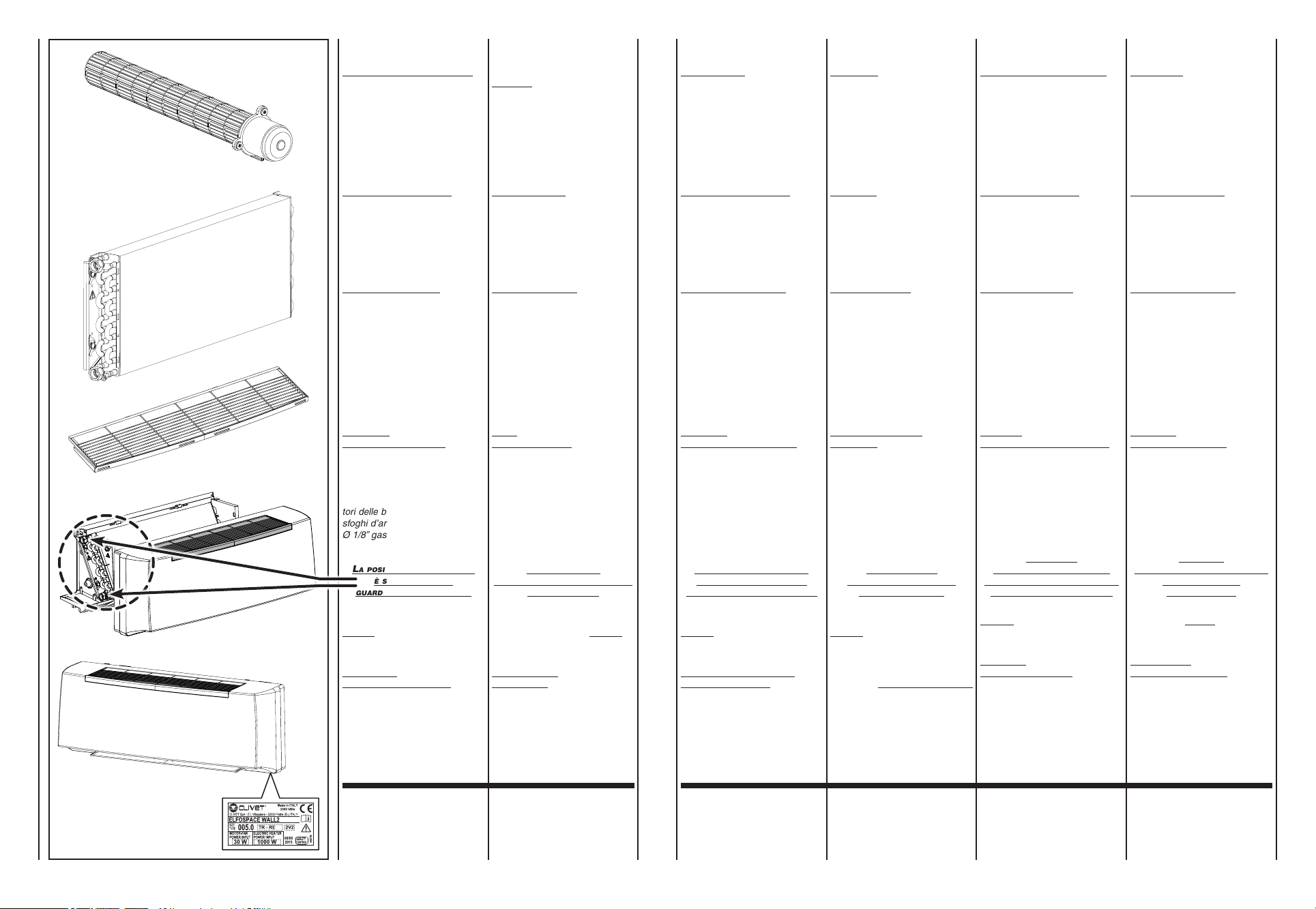
A bordo di ogni singola macchina
è applicata l’etichetta di identifica-
zione riportante i dati del costrut-
tore ed il tipo di macchina.
(vediFig."A")
Each unit is supplied with an
identification plate giving details
of the manufacturer and the type
of appliance.
(seeFig."A")
Une étiquette d’identification est
appliquée sur chaque machine; elle
indique les données du constructeur
et le type de machine.
(voirFig."A")
Jedes Gerät ist mit einem Typen-
schild gekennzeichnet, auf dem
die Daten des Herstellers und der
Typ des Geräts angegeben sind.
(sieheAbb."A")
Cada máquina lleva una placa de
identificación en la que figuran los
datos del fabricante y el tipo de
máquina de que se trata.
(véaselaFig."A")
Aan boord van elk apparaat wordt
een identificatielabel aangebracht
met de gegevens van de fabrikant
en het type machine.
(zieFig."A")
IDENTIFICAZIONE
MACCHINA
IDENTIFYING
THE APPLIANCE
IDENTIFICATION
DES MACHINES
KENNZEICHNUNG
DES GERÄTS
IDENTIFICACIÓN
DE LA MÁQUINA
IDENTIFICATIE
APPARAAT
I componenti principali sono:
MANTELLO DI COPERTURA in
materiale sintetico antiurto. È facil-
mente smontabile per una comple-
ta accessibilità dell’apparecchio.
La griglia di ripresa dell’aria, facen-
te parte del mobiletto, è di tipo ad
alette fisse e posizionato sulla par-
te superiore.
GRUPPO VENTILATORE
Costituito da ventilatore tangen-
ziale, particolarmente silenziosio
con girante in plastica bilanciata
staticamente e dinamicamente,
direttamente calettata sull’albero
motore.
MOTORE ELETTRICO
Di tipo monofase tensione 230V/50 Hz,
isolamento B e klixon integrato.
La variazione di velocità del ventila-
tore avviene con l’impiego di auto-
trasformatore a 6 diverse tensioni
in uscita. Gli apparecchi utilizzano,
come standard, 3 velocità predefinite
con la possibilità, in fase di messa
a punto dell’impianto, di poterle
modificare.
BATTERIA
DI SCAMBIO TERMICO
È costruita con tubi di rame ed
alette in alluminio fissate ai tubi con
procedimento di mandrinatura mec-
canica. La batteria è dotata di 2 at-
tacchi Ø 1/2” gas femmina. I collet-
tori delle batterie sono corredati di
sfoghi d’aria e di scarichi d’acqua
Ø 1/8” gas.
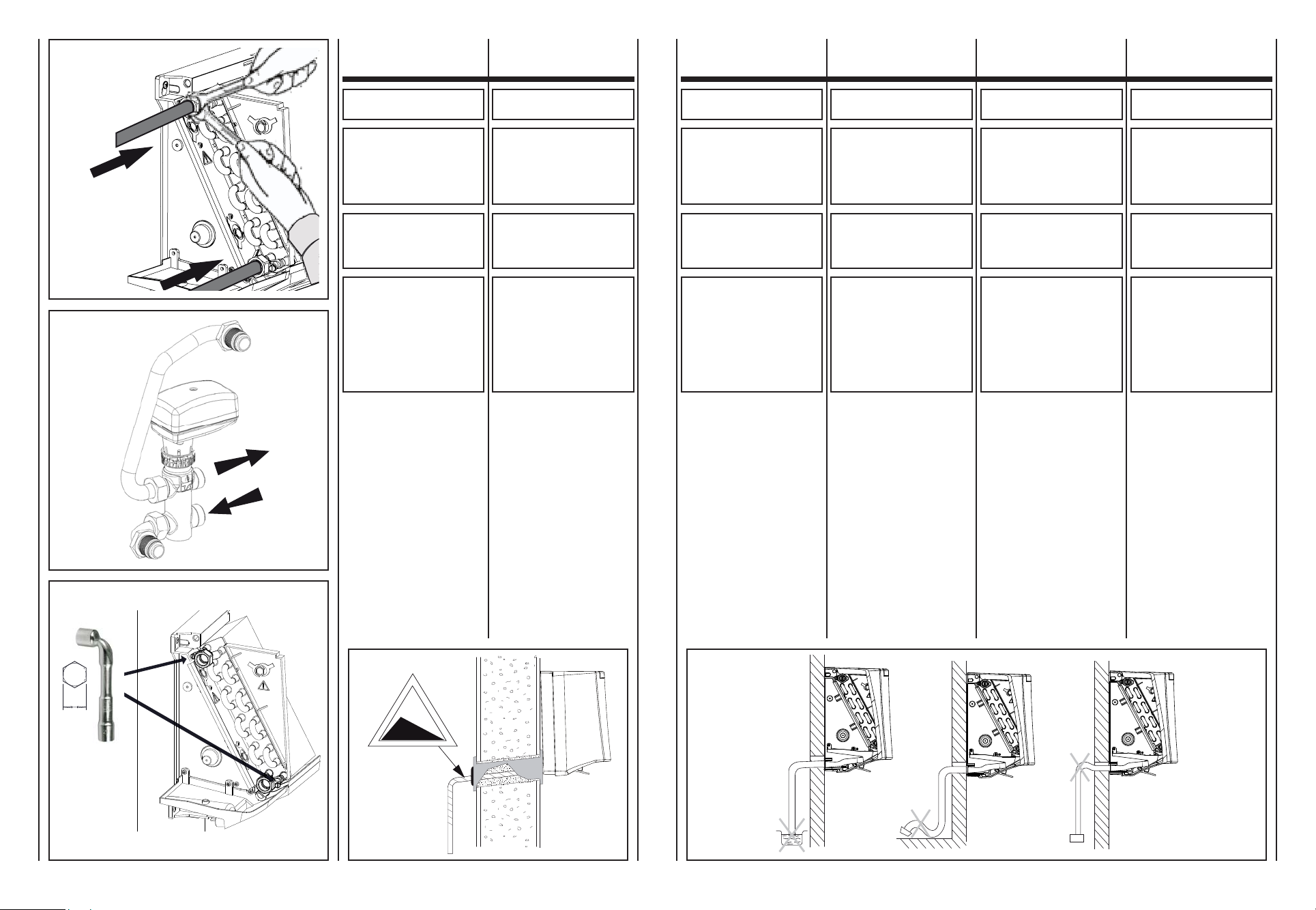
laposIzIone deglI attacchI
èsolo asInIstra,
guardando l’apparecchIo.
FILTRO di materiale sintetico rige-
nerabile.
BACINELLA
RACCOLTA CONDENSA in ma-
teriale plastico, realizzata a forma
di L e fissata alla struttura interna.
The main components are:
impact-proof synthetic material
CASING.
It can be easily disassembled for
complete access to the appliance.
The air intake grill forming part of
the cabinet, has fixed flaps and is
positioned on the upper part.
FAN ASSEMBLY
Consisting of tangential fan,
particularly silent with statically
and dynamically balanced plastic
propeller, directly tapered onto the
motor shaft.
ELECTRIC MOTOR
Of 230V/50 Hz single-phase voltage,
B insulation and integrated klixon
type.
The fan's speed is changed by using
an auto-transformer with 6 different
output voltages. The appliances
standard use 3 pre-defined speeds
with the possibility of modifying them
during system precision adjustment.
HEAT
EXCHANGE COIL
Made with aluminium finned copper
tubes. The exchanger has two 1/2”
female gas connections. Coil headers
with air vents and water drain outlets
(1/8” dia. gas).
the connectIons
are only on the left hand sIde
facIng the unIt.
Regenerable synthetic FILTER.
CONDENSATE
DRAIN PAN,plastic, L-shaped,
fixed to internal structure.
Les composants principaux sont:
CARROSSERIE en matériel synthé-
tique antichoc. Il est facilement
démontable pour accéder totale-
ment à l'appareil.
La grille de reprise d'air, faisant
partie du meuble est de type à
ailettes fixes et placé sur la partie
supérieure.
GROUPE VENTILATEUR
Constitué d'un ventilateur tangentiel,
particulièrement silencieux avec rotor
en plastique équilibré de manière
statique et dynamique, directement
emboîté sur l'arbre moteur.
MOTEUR ÉLECTRIQUE
De type monophasé, tension 230V/50 Hz,
isolation B et klixon intégré.
La variation de vitesse du ventilateur
s'effectue avec l'utilisation d'un auto-
transformateur à 6 tensions différentes
en sortie. Les appareils utilisent, comme
standard, 3 vitesses prédéfinies avec
la possibilité, en phase de mise au
point de l'installation, de pouvoir les
modifier.
BATTERIE
D’ÉCHANGE THERMIQUE
Construite avec des tubes en cuivre
et des ailettes en aluminium fixées
aux tubes par dudgeonnage méca-
nique. La batterie est équipée de
deux raccords Ø 1/2” gaz femelle.
Les collecteurs des batteries sont
dotés de purgeurs d’air et de sorties
d’eau Ø 1/8” gaz.
laposItIon des raccords
est seulement àgauche,
quand on regarde l’appareIl.
FILTRE en matière synthétique
régénérable.
BAC DE RECUPERATION
DES CONDENSATS,en matière
plastique, réalisé en forme de “L“
et fixé à la structure interne.
Das Gerät setzt sich hauptsächlich
aus folgenden Bauteilen zusammen:
GEHÄUSE
Stoßfestes Kunststoffmaterial. Zum
gänzlichen Erreichen des Geräts
einfach zerlegbar.
Das zum Möbelstück gehörende Luft-
einlassgitter besitzt feste Klappen
und ist auf der Oberseite angebracht.
GEBLÄSE
Bestehend aus besonders leisem
Tangentialventilator mit statisch
und dynamisch ausgeglichenem
Laufrad aus Kunststoff, das direkt
mit der Motorwelle verzahnt ist.
ELEKTROMOTOR
Wechselstrom Spannung 230 V/50 Hz,
Isolierung B und eingebautem Klixon.
Die Änderung der Ventilatordrehzahl
erfolgt mithilfe eines Spartransformators
mit 6 unterschiedlichen Ausgangs-
spannungen. Die Geräte verwenden
serienmäßig 3 festgelegte Drehzahlen,
die bei der Feineinstellung der Anlage
geändert werden können.
WÄRMETAUSCHER-
BATTERIE
Bestehend aus Kupferrohren mit
maschinell aufgezogenen Aluminium-
lamellen. Die Wärmetauscher sind
mit zwei Anschlüssen mit Innen-
gewinde ø 1/2” Gas versehen. Die
Sammler der Wärmetauscher sind mit
Entlüftungsöffnungen und Wasserablass-
Anschlüssen ø 1/8” Gas versehen.
dIe anschlüsse
befInden sIch von vorne
gesehen nur lInks.
FILTER aus regenerierbarem
Synthetikmaterial.
An der Innenstruktur befestigte,
L-förmige KONDENSATWANNE
aus Kunststoff.
Los componentes principales son:
MUEBLE DE COBERTURA en
material sintético antichoque. Se
puede desmontar fácilmente para
acceder completamente al aparato.
La rejilla de recuperación del aire,
que forma parte del mueble, es del
tipo con aletas fijas, colocada en
la parte superior.
GRUPO VENTILADOR
Formado por ventilador tangencial,
extremadamente silencioso con
rotor de plástico equilibrado estática
y dinámicamente, directamente
ensamblado al eje motor.
MOTOR ELÉCTRICO
De tipo monofase con tensión de
230V/50 Hz, aislamiento B y klixon
integrado.
La variación de velocidad del ventilador
se realiza usando el auto-transformador
de 6 tensiones de salida diferentes.
Los aparatos, como estándar, utilizan
3 velocidades preconfiguradas con
posibilidad de modificarlas en fase
de puesta a punto de la instalación.
BATERÍA
DE INTERCAMBIO TÉRMICO
Se compone de tubos de cobre y
aletas en aluminio fijadas a los tu-
bos con un procedimiento de man-
drilado mecánico. La batería tiene
2 conexiones Ø 1/2” gas hembra.
Los colectores de las baterías tienen
alivios de aire y descargas de agua
Ø 1/8” gas.
laposIcIón
de las conexIones es sólo
en la parte IzquIerda mIrando
al aparato desde enfrente.
FILTRO en material sintético
regenerable.
BARDEJA
DE CONDENSADOS, en material
plástico, con forma de “L” y asegu-
rada a la estructura interna.
De voornaamste onderdelen zijn:
BEHUIZING
synthetisch, schokwerend materiaal.
Gemakkelijk demonteerbaar, zodat
het toestel volledig toegankelijk is.
Het rooster voor luchtafname, dat
deel uitmaakt van het meubel, is
van het type met vaste vinnen en
bevindt zich aan de bovenkant.
VENTILATORGROEP
Het bestaat uit een tangentiële
ventilator, bijzonder geruisloos, met
statisch en dynamisch uitgebalanceerde
plastic rotor, rechtstreeks verbonden
met de as van de motor.
ELEKTRISCHE MOTOR
Van het type monofase spanning
230V/50 Hz, isolatie B en geïntegreerde
klixon. De snelheidsverandering van de
ventilator gebeurt met behulp van een
spaartransformator met 6 verschillende
spanningen op de uitgang. De toestellen
gebruiken standaard 3 vooraf gedefinieerde
snelheden met de mogelijkheid om die te
wijzigen tijdens de fase waarin het systeem
op punt wordt gesteld.
BATTERIJ
WARMTEWISSELING
Samengesteld uit koperen buizen
en aluminium ribben die met een
mechanisch procédé aan de buizen
bevestigd zijn. De batterij voorzien van
2 vrouwelijke gasaansluitingen van
Ø 1/2” . De collectors van de batterijen
zijn uitgerust met luchtuitlaten en
waterafvoerpijpen van Ø 1/8” gas.
deposItIe
van de aansluItIngen Is lInks,
als men vóór het
apparaat staat.
Herbruikbare FILTER in synthetisch
materiaal.
OPVANGBAK
CONDENSATIEWATER, uitgevoerd
in L-vorm en vastgemaakt aan de
binnenstructuur.
Z
mm
kg
950 950 1255 1255
005.0 007.0 015.0 017.0
005.0 007.0 015.0 017.0
Peso - Weight - Poids - Gewicht - Peso - Gewicht
mod.
11 11 14 14
mod.Dimensioni - Dimensions - Dimensions - Dimensionen - Dimensión - Afmetingen
4
TRASPORTO TRANSPORT TRANSPORT TRANSPORT TRANSPORTE TRANSPORT
L’apparecchio viene imballato in
scatole di cartone.
Una volta che l’apparecchio è
disinballato controllare che non
vi siano danni e che corrisponda
alla fornitura.
In caso di danni o di sigla dell’ap-
parecchio non corrispondente a
quanto ordinato, rivolgersi al pro-
prio rivenditore citando la serie e
il modello.
The appliance is supplied in card-
board packaging.
After unpacking the appliance, make
sure it is undamaged and corresponds
to the unit requested.
In the event of damage or if the
identification code does not
correspond to that ordered, contact
your dealer immediately, quoting
the series and model.
L’appareil est emballé dans des
boîtes en carton.
Après avoir déballé l’appareil, contrôler
qu’il n’a subi aucun dommage et
qu’il correspond bien à la fourniture.
En cas de dommages ou si le sigle
de l’appareil ne correspond pas à
ce qui a été commandé, s’adresser
au revendeur en indiquant la série
et le modèle.
Das Gerät wird in Kartons verpackt.
Kontrollieren Sie beim Auspacken
sofort, ob das Gerät unversehrt ist,
und ob es mit den Angaben in den
Versandpapieren übereinstimmt.
Falls Schäden festgestellt werden
sollten, oder wenn die Artikelnummer
nicht mit dem bestellten Gerät über-
einstimmt, wenden Sie sich bitte an
Ihren Händler. Geben Sie bei Rückfragen
immer Serie und Gerätemodell an.
El aparato viene embalado en caja
de cartón.
Cuando se desembala el aparato,
es preciso comprobar que no tenga
desperfectos y que se corresponda
con el suministro previsto.
En caso de daños o de sigla del
aparato no correspondiente con la
del pedido, dirigirse al revendedor
indicando la serie y el modelo.
Het apparaat wordt in een kartonnen
doos verpakt.
Eens het apparaat van zijn verpakking
ontdaan, controleert u de integriteit
en conformiteit van het apparaat.
In geval van beschadigingen, of
indien het apparaat niet overeenkomt
met de bestelling, wendt u zich tot
uw verkoper, met vermelding van
het serienummer en het model.
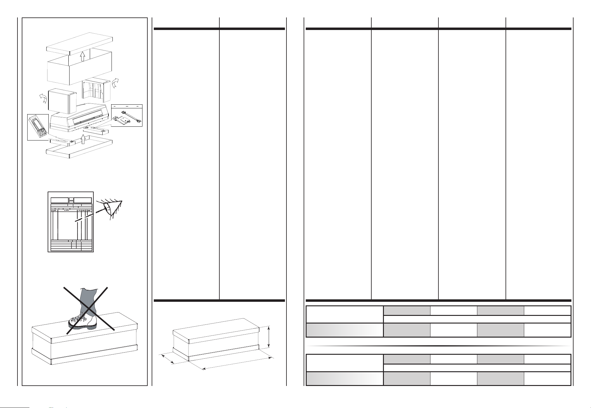
270
Z
395
PESI
E DIMENSIONI
UNITÀ IMBALLATA
WEIGHTS
AND DIMENSIONS
PACKED UNIT
POIDS ET
DIMENSIONS DE
L’UNITE EMBALLEE
GEWICHT
UND DIMENSIONEN
VERPACKTES GERÄT
PESO
Y DIMENSIÓN
UNIDAD EMBALADO
GEWICHT
EN AFMETINGEN
VERPAKTE EENHEID
4A

1
2
ø6
ø6
H
2
O
100mm
ø6 ø6
50mm
50mm
OK OK
• Apparecchio.
• Libretto
di istruzioni e manutenzione.
• Appliance.
• Instruction
and maintenance manual.
• Appareil.
• Instructions
d’installation et d’entretien.
• Gerät.
• Gebrauchs-
und Wartungsanleitung.
• Aparato.
• Manualdeinstrucciones
y mantenimiento.
• Apparaat.
• Handleidingvoorhetgebruik
en het onderhoud.
NOTE
GENERALI
ALLA CONSEGNA
GENERAL
NOTES
ON DELIVERY
REMARQUES
GENERALES POUR
LA LIVRAISON
ALLGEMEINE
HINWEISE
ZUR LIEFERUNG
NOTAS
GENERALES
PARA LA ENTREGA
ALGEMEINE
OPMERKINGEN
BIJ DE LEVERING
5 5A
AVVERTENZE
GENERALI
GENERAL
WARNINGS GENERALITES
ALLGEMEINE
HINWEISE
ADVERTENCIAS
GENERALES
ALGEMENE
VOORSCHRIFTEN
Dopo aver aperto e tolto l’imballo,
accertarsi che il contenuto sia quello
richiesto e che sia integro. In caso
contrario, rivolgersi al rivenditore
ove si è acquistato l’apparecchio.
ATTENZIONE!
Nellaparteinterna
dell’imballosuperiore
è presente
ladimadiinstallazione.
Livellodipressionesonora
ponderatainscalaA<70dB(A)
I ventilconvettori sono stati studiati
per riscaldare e/o condizionare gli
ambienti e devono quindi essere
utilizzati solamente per questo. Si
esclude qualsiasi responsabilità per
i danni eventuali causati da un uso
improprio.
Questo libretto deve accompagna-
re sempre l’apparecchio in quanto
parte integrante dello stesso.
Ogni riparazione o manutenzione del-
l’apparecchio deve essere eseguita da
personale specializzato e qualificato.
Non si risponde in caso di danni
provocati da modifiche o manomis-
sioni dell’apparecchio.
After removing the packaging, make
sure the contents are as requested
and not damaged. If this is not the
case, contact the dealer where you
bought the appliance.
IMPORTANT!
Theinstallationtemplate
is present
insidetheupperpackaging.
TheA-weightedsound
pressurelevel<70dB(A)
The fan coils have been designed
for room heating and/or air conditioning
and must be used exclusively for that
purpose. We declines all responsibility
for damage caused by their improper
use.
This booklet is an integral part of
the appliance and must always
accompany the unit.
All repairs or maintenance must be
performed by qualified specialists.
We declines all responsibility for
damage caused by modifications
or tampering with the unit.
Après avoir ouvert et retiré l’em-
ballage, s’assurer que le contenu
est conforme et qu’il est en parfait
état. En cas contraire s’adresser au
revendeur où l’appareil a été acheté.
ATTENTION!
Surlapartieinterne
del'emballagesupérieur
setrouve
legabaritd'installation.
Leniveaudepressionsonore
pondéréA<70dB(A)
Les ventilo-convecteurs ont été conçus
pour chauffer et/ou climatiser les
pièces et ne doivent être destinés qu’à
cet usage. Il exclut toute responsable
en cas de dommages causés par
un emploi anormal.
Cette notice doit toujours accompa-
gner l’appareil car elle en fait partie
intégrante.
Toutes les réparations ou entretiens de
l’appareil doivent être effectués par le
SAV ou par un technicien spécialisé.
On décline toute responsabilité en cas
de dommages provoqués par
des
modifications ou altérations de l’appareil.
Nach dem Auspacken kontrollieren,
ob der Inhalt der Bestellung entspricht
und unversehrt ist. Im gegenteiligen
Fall wenden Sie sich an Ihren Händler.
ACHTUNG!
InderoberenVerpackung
bendetsich
dieInstallationsschablone.
Der A-gewichtete
Schalldruckpegel<70dB(A)
Die Klimakonvektoren wurden zur
Heizung und Klimatisierung von Räumen
entwickelt und dürfen folglich ausschließlich
zu diesem Zweck verwendet werden. Die
Firma haftet nicht für eventuelle Schäden,
die durch den unzweckmäßigen Gebrauch
verursacht werden.
Diese Betriebsanleitung ist wesentlicher
Bestandteil des Gerätes und muss folglich
immer zusammen mit diesem verwahrt werden.
Alle Reparaturen oder Wartungsarbeiten
müssen durch Personal der Firma oder
andere fachlich qualifizierte Techniker erfolgen.
Die Firma haftet nicht für solche Schäden,
die durch die Veränderung oder die
Manipulierung des Geräts entstehen.
Después de haber retirado el embalaje,
comprobar que el contenido sea el
solicitado y que esté intacto. En caso
contrario, dirigirse al establecimiento
donde se ha comprado el aparato.
ATENCIÓN!
Enlaparteinterna
delembalajesuperior
seencuentralaplantilla
relativaalainstalación.
Elniveldepresiónsonora
conponderaciónA<70dB(A)
Los fan coils se han estudiado para
calentar y/o acondicionar las habita-
ciones y no deben usarse para otro
fin. Declinamos cualquier respon-
sabilidad por los posibles daños
debidos a un uso inadecuado.
Este manual debe acompañar
siempre al aparato ya que forma
parte del mismo.
Todas las reparaciones o manteni-
miento del aparato deberán ser realizadas
por personal especializado y cualificado.
No se hace responsable en caso de
daños provocados por modificacio-
nes o manipulaciones del aparato.
Na de verpakking te hebben verwijderd,
controleren of de inhoud ervan correct
en onbeschadigd is. Is dit niet het geval,
contact opnemen met de verkoper of
waar het apparaat werd aangekocht.
OPGELET!
Indeverpakking
bovenaanbevindt
zichhetschema
voordeinstallatie.
Geluidsdrukniveau
gewogenschaalA<70dB(A)
De ventilatorconvectors werden ontworpen
voor de verwarming en/of koeling van
ruimten, en dienen uitsluitend hiervoor
te worden gebruikt. Wij kunnen niet
aansprakelijk worden gesteld voor
eventuele schade die het gevolg is van
een verkeerd gebruik van het apparaat.
Deze handleiding dient het apparaat
steeds te vergezellen, omdat het er
wezenlijk deel van uitmaakt.
Reparaties of onderhoud van het apparaat
dienen uitgevoerd te worden door
gespecialiseerd en opgeleid personeel.
Wij kunnen niet aansprakelijk worden
gesteld voor schade die voortvloeit
uit aangebrachte wijzigingen.

6 6A
È vietato l’utilizzo del ventilconvet-
tore da parte di bambini o di per-
sone inabili e senza assistenza.
È pericoloso toccare l’apparecchio
avendo parti del corpo bagnate ed
i piedi nudi.
Non effettuare nessun tipo di inter-
vento o manutenzione senza aver
prima scollegato l’apparecchio dal-
l’alimentazione elettrica.
Non manomettere o modificare i
dispositivi di regolazione o sicu-
rezza senza essere autorizzati e
senza indicazioni.
Non torcere, staccare o tirare i
cavi elettrici che fuoriescono dal-
l’apparecchio anche se lo stesso
non è collegato all’alimentazione
elettrica.
Non gettare o spruzzare acqua
sull’apparecchio.
Non introdurre assolutamente nien-
te attraverso le griglie di aspirazio-
ne e mandata aria.
Non rimuovere nessun elemento
di protezione senza aver prima
scollegato l’apparecchio dall’ali-
mentazione elettrica.
Non gettare o lasciare il materiale
residuo dell’imballo alla portata dei
bambini perché potenziale causa
di pericolo.
Non installare in atmosfera esplo-
siva o corrosiva, in luoghi umidi,
all’aperto o in ambienti con molta
polvere.
Fan coils must never be used by
children or unfit persons without
supervision.
It is dangerous to touch the unit
with damp parts of the body and
bare feet.
Always unplug the unit from the
mains power supply before carrying
out any type of operation or
maintenance.
Never tamper with or modify
regulation and safety devices
without prior authorisation and
instructions.
Never twist, detach or pull power
cables, even when the unit is
unplugged from the mains power
supply.
Never throw or spray water on the
unit.
Never introduce foreign objects
through the air intake and discharge
grids.
Never remove protective elements
without first unplugging the unit
from the mains power supply.
Do not throw packaging material
away or leave it within reach of
children as it may represent a
hazard.
Do not install in explosive, corrosive
or damp environments, outdoors
or in very dusty rooms.
Le ventilo-convecteur ne doit pas
être utilisé par des enfants ou des
personnes inaptes non assitées.
Il est dangereux de toucher
l’appareil si on a des parties du
corps mouillées ou les pieds nus.
N’effectuer aucun intervention sur
l’appareil sans l’avoir débranché
au préalable.
Ne pas altérer ou modifier les
dispositifs de réglage ou de sécurité
sans autorisation et sans instructions.
Ne pas tordre, détacher ou tirer
les câbles électriques qui sortent
de l’appareil même si celui-ci est
débranché.
Ne pas jeter ou vaporiser de l’eau
sur l’appareil.
Ne rien introduire à travers les
grilles d’aspiration et de soufflage
de l’air.
N’enlever aucune protection sans
avoir au préalable débranché
l’appareil.
Ne pas jeter ou laisser l’emballage
à la portée des enfants car il peut
représenter un danger.
Ne pas installer l’appareil dans une
atmosphère explosive ou corrosive,
dans des lieux humides, dehors ou
dans des pièces où il y a beaucoup
de poussière.
Der Klimakonvektor darf weder von
Kindern, noch von Personen, die
nicht mit seiner Bedienung vertraut
sind, benutzt werden.
Das Gerät darf weder barfuß noch
mit nassen oder feuchten Körper-
teilen berührt werden.
Das Gerät darf erst gewartet werden,
nachdem die Spannungsversorgung
unterbrochen wurde.
Die Regel- und Sicherheitsein-
richtungen dürfen ohne vorherige
Genehmigung Firma und deren
Anleitung nicht verändert oder
manipuliert werden.
Die aus dem Gerät kommenden
Stromkabel dürfen nicht gezogen,
getrennt, verdreht werden, auch
dann nicht, wenn das Gerät nicht an
das Stromnetz angeschlossen ist.
Das Gerät darf nicht mit Wasser
in Berührung kommen.
Keine Gegenstände durch die Luft-
gitter stecken.
Die Schutzelemente dürfen erst
dann entfernt werden, nachdem die
Spannungsversorgung unterbrochen
wurde.
Das Verpackungsmaterial muss
vorschriftsmäßig entsorgt werden,
und darf nicht in die Reichweite
von Kindern gelangen, da es eine
potentielle Gefahrenquelle darstellt.
Das Gerät darf nicht in explosiver
oder korrosiver Atmosphäre, im
Freien oder in Räumen mit starker
Staubbelastung installiert werden.
Se prohibe el uso del fan coil a los
niños y a las personas incapaci-
tadas no asistidas.
Es peligroso tocar el aparato te-
niendo partes del cuerpo mojadas
y con los pies descalzos.
No efectuar ningún tipo de inter-
vención o mantenimiento sin antes
de haber desconectado el aparato
de la corriente eléctrica.
No manipular o modificar los dispo-
sitivos de regulación o de seguridad
sin la autorización y indicaciones.
No torcer, desconectar o tirar de
los cables eléctricos que salen del
aparato, aunque éste estuviera de-
sconectado de la corriente eléctrica.
No tirar o vaporizar agua sobre el
aparato.
No introducir absolutamente nada
a través de las rejillas de aspira-
ción y descarga de aire.
No retirar ningún elemento de pro-
tección sin antes haber desco-
nectado el aparato de la corriente
eléctrica.
No tirar o dejar al alcance de los
niños el material de embalaje ya
que es una fuente potencial de
peligro.
No instalar en una atmósfera
explosiva o corrosiva, en lugares
húmedos, al aire libre o en lugares
con mucho polvo.
De ventilatorconvector dient niet
te worden gebruikt door kinderen
of onbekwame personen, zonder
toezicht.
Het is gevaarlijk het apparaat aan
te raken wanneer delen van het
lichaam nat zijn of men op blote
voeten loopt.
Verricht geen handelingen of
onderhoud aan het apparaat
vooraleer dit werd losgekoppeld
van het elektriciteitsnet.
De regel- of veiligheidsinrichtingen
worden niet gehanteerd of gewijzigd
zonder toelating.
De stroomkabels die uit het appa-
raat steken, worden niet gekneld,
losgekoppeld of onder trekspanning
gebracht, zelfs wanneer het appa-
raat niet aangesloten is op het
elektriciteitsnet.
Zorg ervoor dat het apparaat niet
in contact komt met water.
Zorg ervoor dat niets door de
aanzuig- en luchtinlaatrooster kan
dringen.
Verwijder geen enkele beveiliging
alvorens het apparaat losgekoppeld
te hebben van het elektriciteitsnet.
Laat het verpakkingsmateriaal
niet rondslingeren of binnen het
bereik van kinderen, omdat het
gevaarlijk kan zijn.
Stel het apparaat niet op in een
explosieve of corrosieve omgeving,
op een vochtige plaats, buiten of
in ruimten met veel stof.
REGOLE
FONDAMENTALI
DI SICUREZZA
FUNDAMENTAL
SAFETY RULES
RÈGLES
FONDAMENTALES
DE SÉCURITÉ
GRUNDSÄTZLICHE
SICHERHEITS-
VORSCHRIFTEN
NORMAS
FUNDAMENTALES
DE SEGURIDAD
BELANGRIJKE
VEILIGHEIDS-
VOORSCHRIFTEN
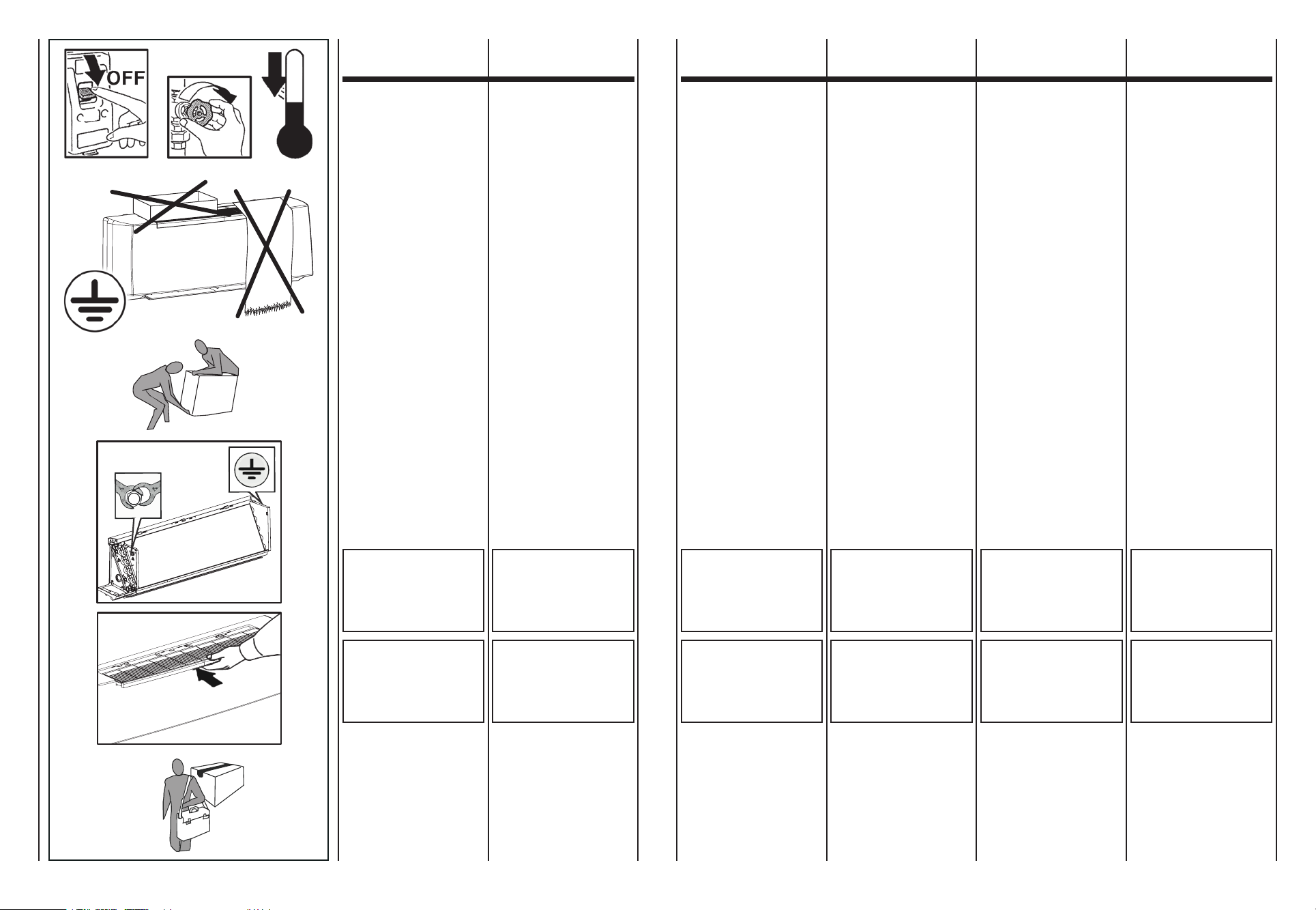
Prima di effettuare qualsiasi inter-
vento assicuratevi che:
1 -
Il ventilconvettore non sia sotto
tensione elettrica.
2 - Chiudere la valvola di alimen-
tazione dell’acqua della batte-
ria e lasciarla raffreddare.
3 -
Installare in prossimità dell’ap-
parecchio o degli apparecchi in
posizione facilmente accessibile
un interruttore di sicurezza che
tolga corrente alla macchina.
Durante l’installazione, la manuten-
zione e la riparazione, per motivi di
sicurezza, è necessario attenersi
a quanto segue:
• Utilizzare
sempre guanti da lavoro.
• Nonesporre
a gas infiammabili.
• Nonposizionare
sulle griglie oggetti.
Assicurarsi
di collegare la messa a terra.
Per trasportare la macchina solle-
varla da soli (per pesi inferiori a 30
Kg) o con l’aiuto di un’altra persona.
Sollevarla lentamente, facendo
attenzione che non cada.
Le ventole possono raggiungere
la velocità di 1000 g/min.
Non inserire oggetti nell’elettro-
ventilatore nè tantomeno le mani.
Non togliere le etichette di sicu-
rezza all’interno dell’apparecchio.
In caso di illeggibilità richiederne
la sostituzione.
Before carrying out any operation
on the appliance, make sure:
1 -
The unit is disconnected from
the electrical power supply.
2 - The coil water supply valve is
closed and the coil has cooled
down.
3 - Install a safety switch to turn
off current to the appliance in
an easily accessible position
near the unit or units.
During installation, maintenance and
repairs, for safety reasons, observe
the following precautions:
• Alwaysuseworkgloves.
• Donotexpose
to inflammable gas.
• Donotplaceobjects
over the grids.
Make sure
the unit is earthed.
When moving the appliance, lift it by
yourself (for weights of under 30 kg)
or with the help of another person.
Lift it slowly, taking care not to
drop it.
Fan blades may reach speeds of
up to 1000 revs/min.
Never introduce objects or the hand
into the fans.
Do not remove the safety labels
inside the appliance.
If you cannot read the labels, ask
for replacements.
Avant d’effectuer toute intervention,
s’assurer que:
1 -
Le ventilo-convecteur n’est pas
sous tension électrique.
2 -
Fermer la vanne d’alimentation
de l’eau de la batterie et la
laisser refroidir.
3 -
Installer à proximité du ou des
appareils et dans une position
facilement accessible un inter-
rupteur de sécurité pour couper
le courant de la machine.
Pendant l’installation, l’entretien
et la réparation, pour des raisons
de sécurité, il est nécessaire de
respecter ce qui suit:
• Utilisertoujours
des gants de travail.
• Nepasexposer
à des gaz inflammables.
• Neplaceraucunobjet
sur les grilles.
S’assurer que la mise à la terre
a été effectuée.
Pour transporter la machine, lav soulever
tout seul (pour des poids inférieurs à
30 kg) ou avec l’aide d’une autre personne.
La soulever lentement, en faisant
attention qu’elle ne tombe pas.
Les ventilateurs peuvent atteindre
la vitesse de 1000 tr/mn.
Ne pas introduire d’objets dans le
ventilateur, et surtout pas les mains.
Ne pas retirer les étiquettes de
sécurité à l’intérieur de l’appareil.
Si les étiquettes sont illisibles, en
demander d’autres exemplaires.
Vor Durchführung irgendwelcher
Eingriffe:
1 -
Sicherstellen, dass der Gebläse-
konvektor nicht unter Spannung steht.
2 - Das Wassereinlassventil der
Batterie schließen und abkühlen
lassen.
3 -
An einer gut zugänglichen Stelle
in der Nähe des Geräts bzw. der
Geräte einen Sicherheitsschalter
installieren, der die Stromzufuhr
zum Gerät unterbricht.
Aus Gründen der Sicherheit sind
während der Installation, Wartung
und Reparaturen, die folgenden
Vorschriften einzuhalten:
• StetsArbeitshandschuhe
tragen.
• Keinenfeuergefährlichen
Gasen aussetzen.
• NichtsaufdieAusblasgitter
stellen.
Vergewissern Sie sich, dass das
Gerät korrekt geerdet wird.
Für den Transport kann das Gerät
alleine (für Gewicht unter 30 kg)
oder zu zweit angehoben werden.
Langsam und vorsichtig anheben,
damit es nicht herabfällt.
Die Laufräder können eine Drehzahl
von 1.000 U/min. erreichen.
Stecken Sie keine Gegenstände in
den Ventilator, und greifen Sie erst
recht nicht mit den Händen hinein.
Die Sicherheitsetiketten im Geräte-
innern dürfen nicht entfernt werden.
Falls Sie unleserlich sind, müssen
sie ersetzt werden.
Antes de efectuar cualquier ope-
ración es preciso comprobar que:
1 - El fan coil no está alimentado
eléctricamente.
2 - Cerrar la válvula de alimenta-
ción del agua de la batería y
dejar que se enfríe.
3 -
Instalar cerca del aparato o de los
aparatos, en una posición a la que
se acceda fácilmente, un interrup-
tor de seguridad que desconecte
la alimentación de la máquina.
Durante la instalación, el manteni-
miento y repación, por motivos de
seguridad, es necesario atenerse
a los siguiente:
• Usarsiempre
guantes de trabajo.
• Noexponer
a gases inflamables.
• Nodejarobjetos
sobre las rejillas.
Comprobar siempre que
esté conectada la toma de tierra.
Para desplazar la máquina basta
una persona (para pesos inferiores
a los 30 Kg) o dos.
Levantarla despacio teniendo cui-
dado en no soltarla.
Los ventiladores pueden alcanzar
una velocidad de 1000 r.p.m.
No introducir objetos en el ventila-
dor ni tanto menos las manos.
No quitar las etiquetas de seguri-
dad presentes dentro del aparato.
Si se estropean hasta quedar ile-
gibles es preciso sustituirlas.
Alvorens u een handeling uitvoert aan
het apparaat, vergewis u ervan dat:
1 -
De ventilatorconvector niet onder
elektrische spanning staat.
2 - De watertoevoerklep van de
batterij gesloten is. Laat deze
laatste afkoelen.
3 - Installeer vlakbij het apparaat
of de apparaten een makkelijk
bereikbare noodschakelaar
die de stroomtoevoer naar de
machine onderbreekt.
Tijdens de installatie, het onderhoud
en de reparaties, is het uit veiligheids-
overwegingen noodzakelijk na te
leven wat volgt:
• Gebruikaltijd
werkhandschoenen.
• Nietblootstellen
aan brandbare gassen.
• Geenvoorwerpen
op de roosters plaatsen.
Zorg
voor een aardaansluiting.
Voor het transport, heft u de machine
alleen (voor gewichten kleiner dan 30
kg) of met de hulp van iemand anders.
Hef de machine traag op, zonder
te laten vallen.
De propellers kunnen een snelheid
van 1000 t/min. halen.
Steek geen voorwerpen of handen
in de elektronventilator.
Verwijder de veiligheidslabels aan de
binnenkant van het apparaat niet.
Als de labels niet leesbaar zijn, laat
u ze vervangen.
7 7A
PRESCRIZIONI
DI SICUREZZA SAFETY RULES
CONSIGNES
DE SECURITE
SICHERHEITS-
VORSCHRIFTEN
PRESCRIPCIONES
DE SEGURIDAD
VEILIGHEIDS-
VOORSCHRIFTEN
ATTENZIONE!
NON TOGLIERE LA
PROTEZIONE
DEL CIRCUITO STAMPATO
DELLA SCHEDA
ELETTRONICA
DALSUPPORTOCOMANDI.
IMPORTANT!
DO NOT REMOVE
THE ELECTRICAL BOARD
PRINTED CIRCUIT
GUARD FROM
THE CONTROL UNIT
MOUNTING.
ATTENTION!
NE PAS RETIRER LA
PROTECTION DU CIRCUIT
IMPRIME DE LA CARTE
ELECTRONIQUE
DU SUPPORT
DESCOMMANDES.
ACHTUNG!
DIE SCHUTZABDECKUNG DER
GEDRUCKTEN SCHALTUNG
DER PLATINE DARF NICHT
VON DER HALTERUNG
DER STEUERUNGEN
GENOMMENWERDEN.
ATENCIÓN!
NO QUITAR LA PROTECCIÓN
DEL CIRCUITO IMPRESO
DA LA TARJETA
ELECTRÓNICA
DEL SOPORTE
DELCONTROL.
OPGELET!
VERWIJDER
DE BEVEILIGING VAN HET
GEDRUKTE CIRCUIT
VAN DE ELEKTRONISCHE
SCHAKELING NIET
ANDEBEDIENINGSBASIS.
IN CASO DI SOSTITUZIONE
O PULIZIA DEL FILTRO
RICORDARSI SEMPRE
DI REINSERIRLO
PRIMA
DELL’AVVIAMENTO
DELL’APPARECCHIATURA.
IF THE FILTER
REQUIRES
REPLACING OR CLEANING,
ALWAYS MAKE SURE
IT IS REPOSITIONED
CORRECTLY BEFORE
STARTINGTHEUNIT.
EN CAS
DE REMPLACEMENT OU
DE NETTOYAGE DU FILTRE,
NE JAMAIS OUBLIER
DE LE REMETTRE
AVANT DE METTRE
L’APPAREILENMARCHE.
BEI ERSATZ ODER
REINIGUNG DES FILTERS
NICHT VERGESSEN, DEN
FILTER VOR DEM
ERNEUTEN EINSCHALTEN
DES GERÄTS WIEDER
EINZUBAUEN.
EN CASO DE SUSTITUCIÓN
O DE LIMPIEZA DEL FILTRO
ACORDARSE SIEMPRE
DE COLOCARLO DE NUEVO
EN SU SITIO ANTES
DE PONER EN MARCHA
ELAPARATO.
ALS U DE FILTER
VERVANGT
OF SCHOONMAAKT,
PLAATST U HEM STEEDS
TERUG VOOR
U HET APPARAAT
INWERKINGSTELT.
In caso di sostituzione di compo-
nenti richiedere sempre ricambi
originali.
In caso di installazioni in climi par-
ticolarmente freddi, svuotare l’im-
pianto idraulico in previsione di
lunghi periodi di fermo macchina.
Nel caso di installazione con serran-
da di presa d’aria esterna fare atten-
zione al gelo invernale che può cau-
sare la rottura dei tubi della batteria.
Always use original spare parts.
In particularly cold climates, if the
appliance is not to be used for long
periods, drain the hydraulic circuit.
If the installation is fitted with an
external air intake damper, make sure
the coil tubes are not damaged by
temperatures below freezing point.
Si l’on doit remplacer des compo-
sants, demander toujours des pièces
de rechange originales.
En cas d’installation dans des climats
particulièrement froids, vidanger l’installation
hydraulique lorsqu’on prévoit de longues
périodes d’arrêt de la machine.
En cas d’installation avec un volet
de prise d’air extérieur, faire attention
au gel en hiver, qui peut provoquer la
rupture des tubes de la batterie.
Verlangen Sie immer Originaler-
satzteile.
Bei Installation in einem besonders
kalten Klima muss der Wasserkreislauf
entleert werden, wenn das Gerät für
längere Zeit nicht benutzt wird.
Achtung bei Installation mit Zuluft-
klappe im Freien, durch winterlichen
Frost können die Rohre der Batterie
beschädigt werden.
En caso de sustitución de compo-
nentes, pedir siempre repuestos
originales.
En caso de instalación en climas parti-
cularmente fríos, vaciar la instalación
hidráulica si se prevén largos plazos
de parada de la máquina.
En caso de instalación con toma
de aire exterior tener cuidado con
el hielo que puede causar la rotura
de los tubos de la batería.
Bij de vervanging van onderdelen,
vraagt u steeds naar originele
wisselstukken.
Voor een installatie in een bijzondere
koude omgeving, ledigt u de hydraulische
installatie als u voorziet dat de machine
gedurende een lange periode niet zal werken.
Voor een installatie met een externe
luchtklep, kijk uit voor wintervorst
die de buizen van de batterij kan
beschadigen.

I dati fondamentali relativi al ventil-
convettore e allo scambiatore di
calore sono i seguenti:
Ventilconvettore
escambiatoredicalore:
• Temperaturamassima
del fluido termovettore:
max 70°C
• Temperaturaminima
del fluido di raffreddamento:
min 6°C
• Pressione
di esercizio massima: 1000 kPa
• Tensionedialimentazione:
230V - 50Hz
• Consumodienergiaelettrica:
vedi targhetta dati tecnici
• Gradodiprotezione:IP20
I dati tecnici delle valvole con
azionatore termoelettrico sono i
seguenti:
Valvolecon
azionatoretermoelettrico:
•
Pressione di esercizio: 1000 kPa
• Tensionedialimentazione:
230V~50/60Hz
• Rating/protezioneVA:
5 VA/IP 44
• Tempodichiusura:180sec.
• Contenutomassimo
di glicole nell’acqua: 50%
Altridatitecnici
Tutti gli altri dati tecnici importanti
(dimensioni, pesi, collegamenti, ru-
morosità, ecc.) vengono forniti in
altre parti del presente Manuale,
nella documentazione tecnica a
parte o nella proposta tecnica.
The basic specification of the fan
coil and heat exchanger is given
below:
Fancoil
andheatexchanger:
• Maximum
temperature
of heat vector fluid: 70°C
• Minimum
temperature
of refrigerant fluid: 6°C
• Maximum
working pressure: 1000 kPa
• Powersupplyvoltage:
230V - 50Hz
• Electricenergyconsumption:
see technical data label
• Indexofprotection:IP20
The technical specification of the
valves with thermoelectric actuator
is given below:
Valveswith
thermoelectricactuator:
• Workingpressure:1000kPa
• Powersupplyvoltage:
230V~50/60Hz
• Rating/VAprotection:
5 VA/IP 44
• Closingtime:180sec.
• Maximumglycolcontent
in water: 50%
Othertechnicaldata
All other important technical data
(dimensions, weights, connections,
noise emissions, etc.) are given
elsewhere in this User Information
Manual, in the separate technical
documentation or in the technical
proposal.
Les caractéristiques fondamentales
du ventilo-convecteur et de l’échan-
geur de chaleur sont les suivantes:
Ventilo-convecteur
etéchangeurdechaleur:
• Températuremaximale
du fluide caloporteur:
70°C maxi
• Températureminimale
du fluide de refroidissement:
6°C mini
• Pression
de marche maximale: 1000 kPa
• Tensiond’alimentation:
230V - 50Hz
• Consommation
d’énergie électrique: voir
plaquette données techniques
• Degrédeprotection:IP20
Les données techniques des
soupapes à actionneur thermo-
électrique sont les suivantes:
Vannes
à
commandethermoélectrique:
• Pressiondemarche:1000kPa
• Tensiond’alimentation:
230V~50/60Hz
• Degrédeprotection:5VA/IP44
• Tempsdefermeture:180sec.
• Contenumaximaldeglycol
dans l’eau: 50%
Autresdonnéestechniques
Toutes les autres caractéristiques
techniques importantes (dimen-
sions, poids, raccordements, bruit
etc.) sont indiquées dans d’autres
parties de ce livret, dans la docu-
mentation technique à part ou dans
la proposition technique.
Die wesentlichen Daten des Klima-
konvektors und der Wärmetauscher
sind die folgenden:
Klimakonvektor
undWärmetauscher:
• Max.Temperatur
des Kältemediums: 70°C
• Min.Temperatur
der Kühlflüssigkeit: 6°C
• Max.
Betriebsdruck: 1000 kPa
• Versorgungsspannung:
230V - 50Hz
• Energieverbrauch:
siehe Typenschild
• Schutzgrad:IP20
Die technischen Daten der thermo-
elektrischen Ventile sind wie folgt:
Ventilemit
thermoelektrischerSteuerung:
• Betriebsdruck:1000kPa
• Versorgungsspannung:
230V~50/60 Hz
• Rating/SicherungVA:
5 VA/IP 44
• Verschlusszeit:180Sek.
• Max.Glykolanteil
im Wasser: 50%
Weitere technische Daten
Alle anderen wichtigen technischen
Daten (Abmessungen, Gewichte,
Anschlüsse, Geräuschpegel, usw.)
sind an anderen Stellen dieses
Handbuchs, in der separaten tech-
nischen Dokumentation oder in den
Angebotsunterlagen enthalten.
Los datos fundamentales relativos
al ventilador convector y al intercam-
biador de calor son los siguientes:
Ventiladorconvector
eintercambiadordecalor:
• Temperaturamáxima
del fluido termovector:
máx. 70°C
• Temperaturamínima
del fluido de enfriamiento:
mín. 6°C
• Máxima
presión de ejercicio: 1000 kPa
• Tensionesdealimentación:
230V - 50Hz
• Consumodeenergíaeléctrica:
ver placa de datos técnicos
• Gradodeprotección:IP20
Los datos técnicos de las válvulas
con accionador termoeléctrico son
los siguientes:
Válvulascon
accionadortermoeléctrico:
• Presióndeejercicio:1000kPa
• Tensióndealimentación:
230V~50/60Hz
• Rating/protecciónVA:
5 VA/IP 44
• Tiempodecierre:180seg.
• Contenidomáximo
de glicol en el agua: 50%
Otrosdatostécnicos
Todos los otros datos técncicos im-
portantes (eida, pesos, conexiones,
ruido, etc.) se dan en otras partes
del presente Manual, en la docu-
mentación técnica.
De belangrijke gegevens met
betrekking tot de ventilator-
convector en de warmtewisselaar:
Ventilator-convector
enwarmtewisselaar:
• Maximumtemperatuur
Vloeistof Thermovector:
max. 70°C
• Minimumtemperatuur
koelvloeistof:
min. 6°C
• Maximale
bedrijfsdruk: 1000 kPa
• Voedingsspanning:
230V - 50Hz
• Elektrisch
energieverbruik: zie plaatje
met technische gegevens
• Beschermingsgraad:IP20
De technische gegevens van de
kleppen met thermo-elektrische
inschakeling:
Kleppenmetthermo-
elektrischeinschakeling:
• Bedrijfsdruk:1000kPa
• Voedingsspanning:
230V~50/60Hz
• Rating/VA-bescherming:
5 VA/IP 44
• Sluitingstijd:180sec.
• Maximaal
glycolgehalte water: 50%
Anderetechnischegegevens
Alle andere belangrijke technische
gegevens (afmetingen, gewichten,
aansluitingen, lawaai, enz.) worden
geleverd in andere delen van de
Handleiding, in de technische
documentatie of door het technisch
personeel.
8 8A
LIMITI DI IMPIEGO OPERATING LIMITS LIMITES D’EMPLOI EINSATZGRENZEN LÍMITES DE USO GEBRUIKSLIMIETEN
SMALTIMENTO
Le parti di consumo e quelle sosti-
tuite vanno smaltite nel rispetto del-
la sicurezza e in conformità con le
norme di protezione ambientale.
WASTE DISPOSAL
Consumables and replaced parts
should be disposed of safely and
in accordance with environmental
protection legislation.
ÉLIMINATION ENTSORGUNG ELIMINACIÓN AFDANKING
Les consommables et les pièces
remplacées doivent être éliminés
en respectant les règles de sécu-
rité et les normes de protection de
l’environnement.
Verbrauchsteile und ersetzte Teile
müssen vorschriftsmäßig entsorgt
werden.
Las partes de consumo y las que
se sustituyen se eliminan respe-
tando la seguridad y de acuerdo
con las normas de protección del
medio ambiente.
De verbruiksonderdelen en vervangen
onderdelen worden afgedankt met
respect voor de veiligheidsvoorschriften
en overeenkomstig de milieuwetgeving.

A
322
212
322
A
A
92
92
20276
C
16281
B
34
164
58
199
ø16
97
8 311
12 97 12
322
8 311
34
37
ø16
ø16
IN
OUT
ATTACCHI IDRAULICI - HYDRAULIC CONNECTIONS - WASSERANSCHLÜSSE
RACCORDS HYDRAULIQUES - CONEXIONES HIDRÁULICAS - HYDRAULISCHE AANSLUITINGEN
9 9A
CARATTERISTICHE
TECNICHE
TECHNICAL
CHARACTERISTIC
CARACTERISTIQUES
TECHNIQUES
TECHNISCHE
EIGENSCHAFTEN
CARACTERÍSTICAS
TÉCNICAS
TECHNISCHE
KARAKTERISTIEKEN
270
Z
395
A
B
C
Z
880
678
691
950
880
678
691
950
1185
983
996
1255
1185
983
996
1255
005.0 007.0 015.0 017.0
mod.
005.0 007.0 015.0 017.0 005.0 007.0 015.0 017.0
13 1113 1117 1417 14
Unitàimballata-Packedunit
Unitéemballée-VerpackungdesGerätes
Unidadembalada-Verpakteeenheid
mod.
Unitànonimballata-Unpackedunit
Unitéseule-UnverpackungdesGerätes
Unidadsinembalar-Eenheidzonderverpakking
005.0 007.0 015.0 017.0
0,85 0,85 1,28 1,28
mod.
005.0 007.0 015.0 017.0
30
0,155
32
0,156
46
0,225
48
0,234
W
A
mod.
230/150Hz
DIMENSIONI - DIMENSIONS - DIMENSIONS
DIMENSIONEN - DIMENSIÓN - AFMETINGEN
PESO - WEIGHT - POIDS
GEWICHT - PESO - GEWICHT
CONTENUTO ACQUA - WATER CONTENTS - CONTENANCE EAU
WASSERINHALT - CONTENIDO AGUA - WATERINHOUD
ASSORBIMENTO MOTORE - MOTOR ABSORPTION - CONSOMMATION MOTEUR
LEISTUNGSAUFNAHME MOTOR - COMSUMO MOTOR - MOTORABSORPTIE
Litri/Liters/Litres
Liter/Litros/Liter
kg
mm
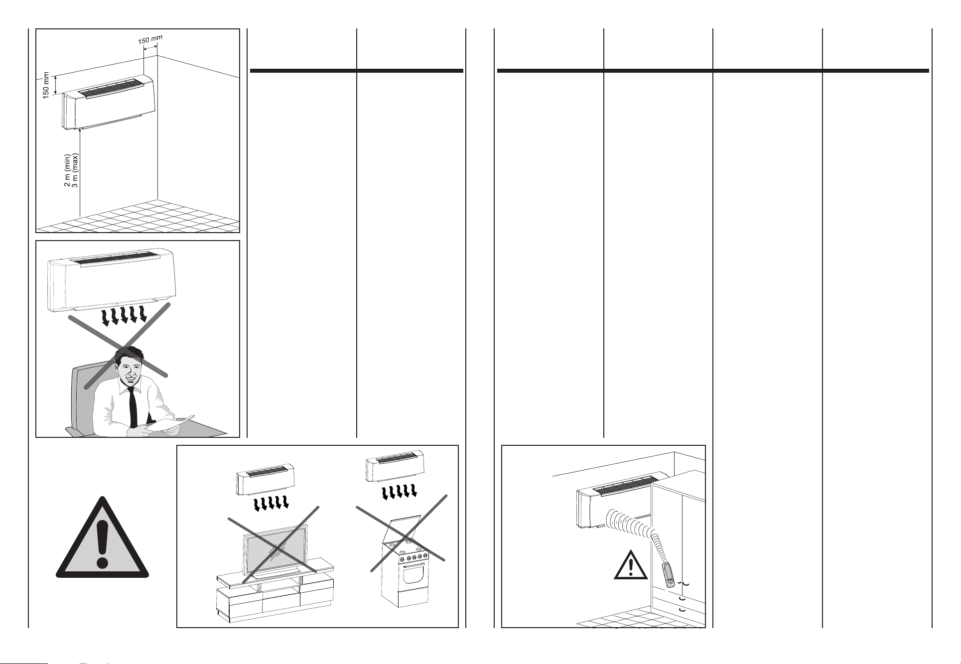
La posizione di installazione del-
l’unità, per ottenere il miglior rendi-
mento di funzionamento ed evitare
guasti o condizioni di pericolo, deve
avere i seguenti requisiti:
- L’altezza dal pavimento del filo
inferiore dell’unità deve essere
minimo di 2 m e massimo di 3 m
(Fig.B).
-
La parete su cui si intende fissa-
re l’unità deve essere robusta e
adatta a sostenerne il peso.
- Deve essere possibile lasciare
attorno all’unità uno spazio neces-
sario per eventuali operazioni di
manutenzione.
-
Non devono essere presenti osta-
coli per la libera circolazione del-
l’aria sia dal lato aspirazione che,
in maggior luogo, su quello di
uscita aria; in questo particolare
caso non deve essere presente
nessun ostacolo ad una distanza
inferiore i 2 m. Ciò potrebbe ca-
usare turbolenze tali da inibire il
corretto funzionamento dell’ap-
parecchio.
- Deve possibilmente essere una
parete esterna in modo da poter
convogliare verso l’esterno il dre-
naggio della condensa.
-
Non deve essere in una posizio-
ne tale che il flusso dell’aria sia
rivolto direttamente alle persone
sottostanti (Fig.C).
- Non sia direttamente sopra ad
un apparecchio elettrodomestico
(televisore, radio, frigorifero, ecc.),
o sopra ad una fonte di calore
(Fig.D).
-
Non siano presenti ostacoli per il
ricevimento dei segnali emessi
dal telecomando (Fig.E).
(Fig.B)
(Abb.B)
(Fig.C)
(Abb.C)
The position for installation of the
unit, to obtain the best performance
and prevent breakdowns or hazards,
must have the following requisites:
- The bottom of the unit must be
at least 2 meters off the floor and
no more than 3 (Fig.B).
- The wall on which the unit is
installed must be sturdy and able
to withstand its weight.
-
It must be possible to leave room
around the unit for any maintenance
operations that may be necessary.
- There should be no obstacles
to the free circulation of air on
the intake side and, especially,
on the air outlet side; on this side,
in particular, there should be no
obstacles closer than 2 m. This
could cause turbulence that would
interfere with correct operation
of the unit.
-
If possible, it should be installed
on an external wall so as to
convey the condensation drain
outside.
- It should not be installed in a
position where the air flow can
strike the people underneath
directly (Fig.C).
- It should not be directly over
another appliance (television set,
radio, refrigerator, etc.), or over
a source of heat (Fig.D).
-
There should be no obstacles for
reception of signals emitted by
the remote control(Fig.E).
Pour obtenir le meilleur rendement
de fonctionnement et éviter les pannes
ou les situations de danger, la position
d’installation de l’unité doit avoir les
caractéristiques suivantes:
- La hauteur du bord inférieur de
l’unité doit être au moins à 2 m et
au maximum à 3 m du sol (Fig.B).
- Le mur sur le quel on souhaite
fixer l’unité doit être solide et apte
à en supporter le poids.
-
Il faut prévoir de laisser l’espace
nécessaire autour de l’unité pour
d’éventuelles opérations d’entretien.
- Il ne doit y avoir aucun obstacle
pour la libre circulation de l’air
tant du côté de l’aspiration que,
à plus forte raison, sur celui de la
sortie de l’air; pour ce dernier cas
il ne doit y avoir aucun obstacle à
une distance inférieure à 2 m. Cela
pourrait causer des turbulences qui
pourraient empêcher le fonctionne-
ment correct del’appareil.
-
Il est préférable, autant que possible,
que ce soit un mur donnant sur
l’extérieur de sorte que l’on puisse
diriger le drainage de la condensation
au dehors.
-
L’installation ne doit pas être dans
une position telle que le soufflage
de l’air soit dirigé directement sur
les personnes placées au-dessous
(Fig.C).
-
Elle ne doit pas être directement
audessus d’un appareil électro-
ménager (téléviseur, radio, réfri-
gérateur, etc.), ou au-dessus d’une
source de chaleur (Fig.D).
-
Il ne doit pas y avoir d’obstacles
pour la réception des signaux émis
par la télécommande(Fig.E).
La posición de instalación de la uni-
dad, para obtener el mejor rendi-
miento de funcionamiento y evitar
daños o condiciones de peligro, tiene
que tener los siguientes requisitos:
-
La altura desde el suelo del borde
inferior de la unidad tiene que
ser de un mínimo de 2 m y un
máximo de 3 m (Fig.B).
-
La pared sobre la que se quiere
fijar la unidad tiene que ser robu-
sta y apta para sostener el peso.
- Tiene que ser posible dejar
alrededor de la unidad un espacio
necesario para eventuales ope-
raciones de mantenimiento.
- No tiene que haber obstáculos
para la libre circulación del aire
tanto del lado de aspiración que,
sobre todo, del lado de salida de
aire; en este caso en particular
no tiene que haber ningún obstá-
culo a una distancia inferior de 2 m.
Esto podría causar turbulencias
tales que inhiban el correcto fun-
cionamiento del equipo.
-
Posiblemente tiene que ser una
pared externa de modo tal de
poder transportar hacia el exterior
el drenaje de la condensación.
-
No tiene que encontrarse en una
posición tal que el flujo de aire se
dirija directamente a las personas
subyacentes (Fig.C).
-
No se encuentre directamente por
encima de un electrodoméstico
(como por ejemplo: televisor, radio,
frigorífico, etc.), o sobre una fuente
de calor (Fig.D).
-
No haya obstáculos que impidan
la recepción de las señales emitidas
por el mando a distancia(Fig.E).
Om het beste werkingsrendement te
bekomen en om defecten of gevaarlijke
situaties te vermijden, moet de
installatiepositie van de eenheid aan
de volgende vereisten voldoen:
- De hoogte boven de vloer van
de onderste lijn van de eenheid
moet minimaal 2 m en maximaal
3 m bedragen (Fig.B).
-
De wanden waarop men de eenheid
wil bevestigen, moet stevig zijn en
geschikt om het gewicht te dragen.
-
Rond de eenheid moet men voldoende
ruimte kunnen laten voor eventuele
onderhoudswerkzaamheden.
-
Er mogen geen obstakels aanwezig
zijn voor de vrije luchtcirculatie,
zowel aan de kant van de aanzuiging
als aan de kant van de luchtuitlaat,
wat nog belangrijker is; in dit laatste
geval mag er geen enkel obstakel
aanwezig zijn op een afstand van
minder dan 2 m. Dit zou turbulenties
kunnen veroorzaken, die bijgevolg de
correcte werking van het toestel
beletten.
-
Indien mogelijk moet er een externe
wand zijn, zodat de afgevoerde
condens naar buiten kan worden
geleid.
-
Die mag niet in een stand staan
waardoor de luchtstroom rechtstreeks
naar personen eronder is gericht
(Fig.C).
-
De positie mag niet rechtstreeks
boven een huishoudtoestel
(televisie, radio, koelkast, enz.)
of boven een warmtebron zijn
(Fig.D).
-
Er mogen geen obstakels zijn voor
de ontvangst van signalen die door
de afstandsbediening worden
verzonden (Fig.E).
Zur Gewährleistung einer einwandfreien
Funktionsweise und zur Vorbeugung von
Betriebsstörungen und Gefahren ist bei der
Wahl der Stelle, an der die Einheit installiert
werden soll, auf Folgendes zu achten:
-
Der Abstand zwischen dem Fußboden
und der unteren Kante der Einheit
muss mind. 2 mbis max. 3 m
betragen (Abb.B).
- Die Wand, an der die Einheit
befestigt wird, muss dem Gewicht
derselben standhalten.
-
Die Einheit ist so anzubringen, dass
an dieser jederzeit und problemlos
eventuelle Wartungseingriffe
vorgenommen werden können.
- An der Luftansaug- und Luft-
auslassseite dürfen sich in einem
Abstand von mind. 2 m keine
Hindernisse befinden, da dies zu
Turbulenzen führen könnte, die
die einwandfreie Funktionsweise
des Gerätes beeinträchtigen
könnten.
- Nach Möglichkeit sollte eine
Außenwand vorhanden sein, damit
das Kondenswasser ins Freie
abgeleitet werden kann.
- Bei der Installation der Einheit
ist darauf zu achten, dass der
Luftstrom nicht direkt auf sich
darunter befindliche Personen
gerichtet ist (Abb.C).
-
Die Einheit darf nicht über einem
Elektrogerät (TV, Radio, Kühl-
schrank, usw.) oder über einer
Wärmequelle installiert werden
(Abb.D).
-
Es ist darauf zu achten, dass das von
der Fernbedienung gesendete Signal
auf keine Hindernisse trifft (Abb.E).
10 10A
SCELTA
DELLA POSIZIONE
DELL’UNITÀ
SELECTION
OF POSITION
OF THE UNIT
CHOIX
DE LA POSITION
DE L’UNITE
POSITIONIERUNG
DER EINHEIT
ELECCIÓN
DE LA POSICIÓN
DE LA UNIDAD
POSITIONERINGS-
EENHEID
(Fig.D)
(Abb.D)
(Fig.E)
(Abb.E)

B
C
276
281
4
ø6
678
983
B
691
996
C
005.0
–
007.0
015.0
–
017.0
mod.
10
1
2
OK
OK
Paretiincartongessoolegno
Woodorplasterboardwalls
Mursenplacoplâtreouenbois
WändeausGipskartonoderHolz
Paredesdecartón-yesoodemadera
Wandeningipsplaatofhout
11 11A
INSTALLAZIONE
MECCANICA
MECHANICAL
INSTALLATION
INSTALLATION
MECANIQUE
MECHANISCHE
INSTALLATION
INSTALACIÓN
MECÁNICA
MECHANISCHE
INSTALLATIE
4
1
2 6
3
5
Nel caso l’apparecchio sia fornito
di valvola collegare i tubi di colle-
gamento alla valvola stessa.
Se l’apparecchio è usato per raf-
freddare, per evitare gocciolamento
di condensa, isolare le tubazioni e
la valvola.
Nei periodi estivi e per lunghi pe-
riodi di tempo con il ventilatore di-
sinserito, per evitare formazioni di
condensa all’esterno dell’apparec-
chio, si consiglia di intercettare
l’alimentazione della batteria.
Nel caso venga richiesta la va-
schetta supplementare, raccolta
condensa, questa va fissata alla
struttura dal lato attacchi e il tubo
di scarico condensa va collegato
a quest’ultima.
If the unit is fitted with a valve,
connect the connection pipes to
the valve.
If the unit is used for cooling,
insulate the pipes and valve to
avoid drops of condensate forming.
During the summer and when the
fan is inactive for long periods, you
are recommended to shut off the
water supply to the coil to avoid
condensation forming on the outside
of the unit.
If a supplementary condensate
drain pan is used, this should be
fixed to the connections side of
the frame and the condensate
drain pipe should be fastened to
the latter.
Si l’appareil est équipé d’une vanne,
brancher les tuyauteries de raccorde-
ment à cette même vanne.
Si on utilise l’appareil pour rafraîchir,
isoler les tuyauteries et la vanne
afin d’éviter des égouttements de
condensats.
Pendant l’été et lorsque le ventilateur
reste longtemps débranché, il est
conseillé d’isoler l’alimentation de la
batterie afin d’éviter les formations
de condensation à l’extérieur de
l’appareil.
Si le bac supplémentaire (de récupé-
ration des condensats) est demandé,
il doit être fixé à la structure du côté
des raccords et le tuyau d’évacuation
des condensats doit être raccordé
à ce bac.
Falls das Gerät mit Ventil ausgestattet
ist, die Anschlussleitungen mit dem
Ventil verbinden.
Wenn das Gerät zum Kühlen benutzt
wird, müssen die Rohrleitungen und das
Ventil isoliert werden, um ein Heraustropfen
von Kondenswasser zu vermeiden.
Im Sommer und wenn der Ventilator
für längere Zeit nicht benutzt wird,
empfiehlt sich, die Zuleitung zur
Batterie zu sperren, damit sich
außen am Gerät kein Kondens-
wasser bildet.
Falls eine zusätzliche Kondensat-
wanne verlangt wird, wird diese auf
der Anschlussseite an der Struktur
befestigt und die Kondensatablauf-
leitung wird daran angeschlossen.
Si el aparato lleva válvula, conectar
los tubos de enlace con la propia
válvula.
Si se usa el aparato para enfriar,
para evitar goteos de condensado
es preciso aislar las tuberías y la
válvula.
En las temporadas veraniegas y
cuando se prevea dejar apagado el
ventilador por mucho tiempo, para evitar
formaciones de condensado al exterior
del aparato se aconseja interceptar el
agua de alimentación de la batería.
En el caso de que se requiera la
pileta suplementaria, de recogida
del condensado, es preciso fijarla
a la estructura por el lado conexiones
y el tubo de descarga del conden-
sado debe conectarse a esta última.
Indien het apparaat uitgerust is met
een klep, sluit u de buizen rechtstreeks
aan op de klep.
Als het apparaat wordt gebruikt om
af te koelen, en om het druppelen
van condenswater te voorkomen,
isoleert u de buizen en de klep.
In de zomermaanden en indien de
ventilator lange tijd niet wordt gebruikt,
is het raadzaam de voeding van de
batterij te onderbreken, om de vorming
van condensatievocht aan de buitenkant
van het apparaat te voorkomen.
Als voor het opvangen van het
condensatievocht het gebruik van
een bijkomende opvangbak wordt
gevraagd, wordt deze bevestigd
aan de structuur, aan de zijde van
de aansluitingen; de afvoerbuis
wordt aangesloten aan deze laatste.
OUT
IN
3%
8
12 12A
COLLEGAMENTO
IDRAULICO
HYDRAULIC
CONNECTIONS
RACCORDEMENT
HYDRAULIQUE
WASSERANSCHLUSS
ENLACE
HIDRÁULICO
HYDRAULISCHE
AANSLUITING
PRESSIONE MASSIMA
DIESERCIZIO:1000kPa.
MAXIMUM WORKING
PRESSURE:1000kPa.
PRESSION MAXI
DESERVICE:1000kPa.
MAXIMALE
BETRIEBSDRUCK:1000kPa.
PRESIÓN MÁXIMA
DEOPERACIÓN:1000kPa.
MAXIMALE
BEDRIJFSDRUK:1000kPa.
USARE SEMPRE
CHIAVE E CONTROCHIAVE
PER L’ALLACCIAMENTO
DELLA BATTERIA
ALLETUBAZIONI.
ALWAYS USE
TWO SPANNERS
TO CONNECT
THE HEAT EXCHANGER
TOTHEPIPES.
UTILISER TOUJOURS
UNE CLE
ET UNE CONTRE-CLE
POUR LE RACCORDEMENT
DE LA BATTERIE
AUXTUYAUTERIES.
FÜR DEN ANSCHLUSS
DER BATTERIE
AN DIE ROHRLEITUNGEN
IMMER SCHLÜSSEL
UND GEGENSCHLÜSSEL
BENUTZEN.
USAR SIEMPRE
LLAVE Y CONTRALLAVE
PARA ENLAZAR
LA BATERÍA
ALASTUBERÍAS.
GEBRUIK
STEEDS SLEUTELS
EN TEGENSLEUTELS
OM DE BATTERIJ
TE VERBINDEN
METDEBUIZEN.
PREVEDERE SEMPRE
UNA VALVOLA
DI INTERCETTAZIONE
DELFLUSSOIDRAULICO.
ALWAYS
FIT A GATE VALVE
INTHEWATERCIRCUIT.
PREVOIR TOUJOURS
UNE VANNE D’ARRET
DUFLUXHYDRAULIQUE.
IMMER EIN SPERRVENTIL
DES WASSERFLUSSES
INSTALLIEREN.
PREVER SIEMPRE
UNA VÁLVULA
DE ABRE-CIERRE
DEL FLUJO HIDRÁULICO
VOORZIE STEEDS EEN
RETOURKLEP.
ATTENZIONE!
È CONSIGLIATO SIFONARE
LO SCARICO
DELLA CONDENSA,
INSTALLARE
IL TUBO
DI SCARICO CONDENSA
CON UNA PENDENZA
DIALMENO3cm/metro.
IMPORTANT!
YOU ARE RECOMMENDED
TO FIT A SIPHON
ON THE CONDENSATE
DRAIN.INSTALL
A CONDENSATE
DRAIN PIPE
WITH A SLOPE OF
ATLEAST3cm/metre.
ATTENTION!
IL EST CONSEILLE DE
SIPHONER L’EVACUATION
DES CONDENSATS
ET D’INSTALLER LE TUYAU
D’EVACUATION
DES CONDENSATS
AVEC UNE PENTE
D’AUMOINS3cm/m.
ACHTUNG!
DER KONDENSATAUSLASS
SOLLTE MÖGLICHST MIT
EINEM SIPHON VERSEHEN,
UND DIE KONDENSAT-
ABLAUFLEITUNG
MIT EINER NEIGUNG VON
MINDESTENS3cm/Meter
INSTALLIERTWERDEN.
ATENCIÓN!
SE ACONSEJA COLOCAR
UN SIFÓN EN LA DESCARGA
DEL CONDENSADO,
INSTALAR EL TUBO
DE DESCARGA
DEL CONDENSADO
CON UNA PENDIENTE DE
PORLOMENOS3cm/metro.
OPGELET!
HET IS RAADZAAM
DE AFVOERBUIS VAN HET
CONDENSATIEVOCHT
TE HEVELEN,
EN DE AFVOERBUIS
TE INSTALLEREN MET EEN
HELLING VAN MINSTENS
3cm/meter.

1Ventilatore
2Scambiatore di calore
3Sfiato aria manuale
4Giunto di collegamento
(fornito a corredo)
5Valvola
di intercettazione a sfera
1Fan
2Heat exchanger
3Air valve
4Joint (supplied)
5Ball shutoff valve
1Ventilateur
2Échangeur de chaleur
3Purgeur air manuel
4Manchette de raccord (fourni)
5Vanne d’arrêt à bille
1Ventilator
2Wärmetauscher
3Manuelle Entlüftung
4Anschluss (mitgeliefert)
5Kugelabsperrventil
1Ventilador
2Intercambiadores de calor
3Purgador de aire manual
4Junta de conexión
(entregada juntocon el aparato)
5Válvula de corte de esfera
1Ventilator
2Warmtewisselaar
3Handmatige ontluchting
4Verbindingselement
(meegeleverd)
5Kogelafsluitklep
13 13A
Collegamenti eseguiti
in fabbrica
Collegamenti a cura
dell’installatore
Uscita
Outlet
Sortie
Entrata
Inlet
Entrée
3
12
4 5
45
3
Connections carried
out by the installer
Connections carried
out in the factory
Raccordements à
réaliser par l'installateur
Raccordements
effectués en usine
Collegamenti eseguiti
in fabbrica
Collegamenti a cura
dell’installatore
Uscita
Outlet
Sortie
Entrata
Inlet
Entrée
3
12
4 5
45
3
Connections carried
out by the installer
Connections carried
out in the factory
Raccordements à
réaliser par l'installateur
Raccordements
effectués en usine
Collegamenti
eseguiti in fabbrica
Connections
carried out in the factory
Raccordements
effectués en usine
Uscita
Outlet
Sortie
Austritt
Salida
Afvoer
Entrata
Inlet
Entrée
Eintritt
Entrada
Inlaat
Werksseitig
ausgeführte Anschlüsse
Conexiones
realizadas en fábrica
Aansluitingen
uitgevoerd in de fabriek
Collegamenti
a cura dell’installatore
Connections
carried out by the installer
Raccordements
à réaliser par l'installateur
Vom Installateur
auszuführende Anschlüsse
Conexiones que
debe realizar el instalador
Aansluitingen ten laste
van de installateur
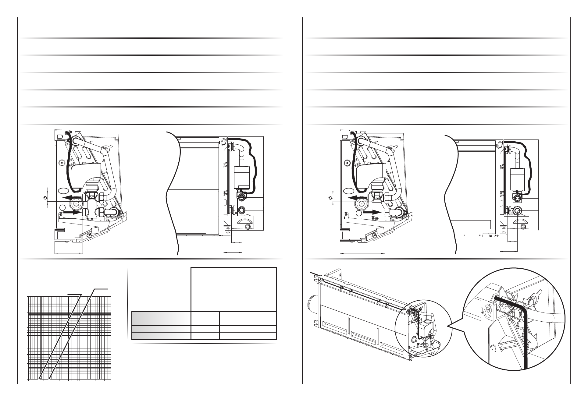
56
19040
31
63
77
IN
OUT
77
IN
OUT
56
19040
31
63
Kvs 2,5
Kvs 1,6
40
30
20
10
9
8
7
6
5
4
3
2
1
100 200 300 400 600 800 1000 2000 3000 4000
Portata acqua (l/h) - Water flow (l/h)
Débit d’eau (l/h) - Wasserdurchflussmenge (l/h)
Caudal de agua (l/h) - Waterdebiet (l/h)
Dp - kPa
Valvolaa2vieperbatteriaprincipale2V2
Valvola a 2 vie ON-OFF 230 V (accessorio optional).
2V2
2wayvalveformaincoil
Control valve kit: 2 way valve, ON-OFF, with electric motor and mounting kit (optional).
Vannepourbatterieprincipale2V2
Vanne 2 voies (ON-OFF), avec servomoteur et kit de montage (option).
2-Wege-WasserventilfürHauptregister2V2
2-Wege-Wasserventil ON-OFF 230 V mit elektrischem Motor und Montage KIT (optional).
Válvulaparabateríaprincipal2V2
Válvula eléctrica de dos vías ON-OFF, con actuador eléctrico y kit de montaje (opción).
Tweewegshoofdklepvoorhoofdbatterij2V2
Tweewegsklep ON-OFF 230 V (optioneel accessoire).
Valvolaa3vieperbatteriaprincipale3V2
Valvola acqua a tre vie ON-OFF 230 V e kit di montaggio (accessorio optional).
3V2
mainbattery3wayvalve
Control valve kit: 3 way valve, ON-OFF, with electric motor and mounting kit (optional).
Vannepourbatterieprincipale3V2
Vanne 3 voies (ON-OFF), 230V et kit de montage (option).
3-Wege-WasserventilfürHauptregister3V2
3-Wege-Wasserventil ON-OFF 230 V mit elektrischem Motor und Montage KIT (optional).
Válvulaparabateríaprincipal3V2
Válvula agua de tres vías ON-OFF, con actuador eléctrico y kit de montaje (opción).
Klepvoorhoofdbatterij3V2
Driewegswaterklep ON-OFF, met elektrische bediening en montagekit (optioneel accessoire).
14 14A
Valvola
Valve
Vanne
Wasserventil
Válvula
Klep
15
20
DN
1/2” G
3/4” G
(Ø)
1,6
2,5
Kvs
005.0 – 007.0
015.0 – 017.0
mod.
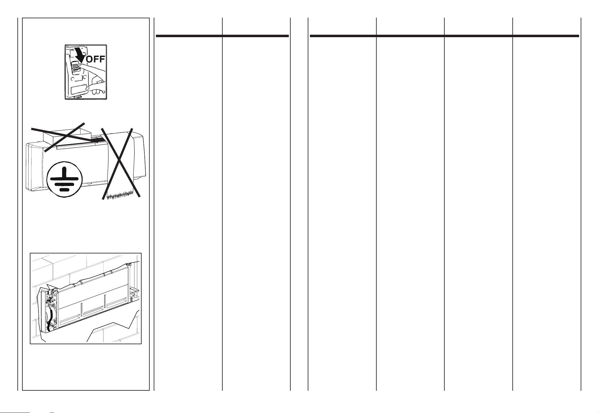
15 15A
COLLEGAMENTI
ELETTRICI
ELECTRICAL
CONNECTIONS
BRANCHEMENTS
ELECTRIQUES
ELEKTRO-
ANSCHLÜSSE
CONEXIONES
ELECTRICAS
ELEKTRISCHE
AANSLUITINGEN
Prescrizionigenerali
• Prima di installare il ventilcon-
vettore verificare che la tensione
nominale di alimentazione sia
di 230V - 50 Hz.
• Assicurarsi che l’impianto elet-
trico sia adatto ad erogare, oltre
alla corrente di esercizio richie-
sta dal ventilconvettore, anche la
corrente necessaria per alimen-
tare elettrodomestici ed appa-
recchi già in uso.
•
Effettuare i collegamenti elettrici
secondo le leggi e le norme na-
zionali vigenti.
•
A monte dell’unità prevedere un
interruttore onnipolare con di-
stanza minima dei contatti di 3,5
mm.
Occorre sempre effettuare la mes-
sa a terra dell’unità.
Togliere sempre l’alimentazione
elettrica prima di accedere alla
macchina.
Indicazioni
perilcollegamento
L’apparecchio è equipaggiato con
scheda elettronica posta sulla fian-
cata interna, lato opposto attacchi
idraulici. Il collegamento deve esse-
re effettuato rispettando gli schemi
elettrici riportati sul presente libretto.
L’installatore dovrà prevedere l’in-
gresso dei cavi di collegamento
utilizzando gli accessi previsti, ov-
vero:
• da muro utilizzando l’apertura
posteriore resa disponibile in
corrispondenza della fiancata.
Generalinstructions
•
Before installing the fan coil, make
sure the rated voltage of the power
supply is 230V - 50 Hz.
• Make sure that, in addition to
supplying the working current
required by the fan coil, the mains
electrical supply is also able to
supply the current necessary
to operate other household
appliances and units.
• Perform electrical connections
in accordance with laws and
regulations in force in the country
concerned.
• Upstream of the unit, t an
omnipolar switch with minimum
contact distance of 3,5 mm.
The unit must always be earthed.
Always disconnect the electrical
power supply before opening the
unit.
Connection instructions
The appliance is equipped with
electronic power board located on
the inner side, opposite to hydraulic
connections. The connection must be
made respecting the wiring diagrams
in this book.
The installer must bring the connecting
wires into the unit through the access
points provided:
• wall-mounted, using the rear
access point corresponding to
the side panel.
Instructions
• Avant d’installer le ventilo-con-
vecteur vérifier que la tension
d’alimentation nominale est de
230V - 50Hz.
• S’assurer que la puissance de
l’installation électrique est suffi-
sante pour fournir le courant de
marche pour le ventilo-convecteur
ainsi que le courant nécessaire
pour alimenter les électroménagers
et les appareils déjà utilisés.
• Effectuer les branchements
électriques selon la législation et
les normes nationales en vigueur.
• En amont de l’unité prévoir un
interrupteur unipolaire avec
distance minimum des contacts
de 3,5 mm.
Il faut toujours effectuer la mise à
la terre de l’unité.
Débrancher toujours la machine
avant d’y accéder.
Indications
pourleraccordement
L'appareil est équipé d'une carte
électronique située sur le côté interne,
sur le côté opposé des raccords
hydrauliques. Le raccordement doit être
effectué en respectant les schémas
électriques reportés dans ce manuel.
L’installateur devra prévoir l’entrée
des câbles de raccordement en uti-
lisant les accès prévus, c’est-à-dire:
•
sur le mur en utilisant l’ouverture
postérieure disponible près du
côté.
AllgemeineAnweisungen
• Vor der Installation des Klima-
konvektors sicherstellen, dass
die nominale Versorgungs-
spannung 230V - 50 Hz beträgt.
• Sicherstellen,dassdieElektro-
anlage in der Lage ist, neben
dem Klimakonvektor auch die
anderen Haushaltsgeräte zu
versorgen.
• Die Elektroanschlüsse müssen
gemäß der einschlägigen Gesetze
und Vorschriften hergestellt
werden.
• Dem Gerät einen allpoligen
Schalter mit einer Kontaktöffnung
von mindestens 3,5 mm vorschalten.
Das Gerät vorschriftsmäßig erden.
Vor dem Zugriff auf das Geräte-
innere stets die Spannungs-
versorgung unterbrechen.
Anleitungen
fürdenAnschluss
Das Gerät ist mit elektronischer
Leistungskarte auf der Innenseite,
gegenüber den Hydraulikanschlüssen,
ausgestattet. Beim Anschluss müssen
die dieser Anleitung beiliegenden
Schaltpläne berücksichtigt werden.
Der Installateur muss die Durch-
gänge der Anschlusskabel an den
vorhergesehenen Stellen ausführen,
und zwar:
•
Von der Wand her unter Verwendung
der hinteren Öffnung auf Höhe
der Seitenwand.
Prescripcionesgenerales
• Antes de instalar el ventilador
convector verificar que la tensión
nominal de alimentación sea de
230 V - 50 Hz.
•
Asegurarse de que la instalación
eléctrica sea apta para distribuir,
además de la corriente de ejer-
cicio requerida por el ventilador
convector, la corriente necesaria
para alimentar electrodomésticos
que ya se estuvieran usando.
• Efectuarlasconexioneseléctri-
cas de acuerdo con las leyes y
las normativas nacionales vigentes.
•
Prever, más arriba de la unidad,
un interruptor omnipolar con una
distancia mínima de los contac-
tos de 3,5mm.
Realizar siempre la toma de tierra
de la unidad.
Retirar siempre la corriente eléctri-
ca antes de acceder a la máquina.
Indicaciones
paralaconexión
El aparato está equipado con tarjeta
electrónica colocada en la parte lateral
interna, en el lado opuesto al de las
conexiones hidráulicas. La conexión debe
hacerse respetando los esquemas eléc-
tricos indicados en el presente manual.
El instalador deberá prever la en-
trada de los cables de conexión
usando los accesos previstos, es
decir:
• desdelaparedusandolaaper-
tura posterior disponible en el
lateral.
Algemenevoorschriften
• Alvorensdeventilatorconvector
te installeren, wordt gecontroleerd
of de nominale voedingsspanning
gelijk is aan 230V - 50 Hz.
• Waakeroverdatdeelektrische
installatie in staat is om, naast
de bedrijfstroom vereist door de
ventilatorconvector, de nodige
energie te leveren voor de voeding
van de reeds in gebruik zijnde
huishoudtoestellen en apparaten.
• De elektrische aansluitingen
uitvoeren volgens de geldende
nationale wetgevingen en normen.
•
Stroomopwaarts van de eenheid
wordt een meerpolige schakelaar
voorzien met een minimale afstand
tussen de polen van 3,5 mm.
De eenheid moet in elk geval worden
uitgerust met een aardaansluiting.
Koppel altijd eerst de elektrische
voeding los alvorens aan het
apparaat te komen.
Aanwijzingen
voordeaansluiting
Het toestel is uitgerust met een elektronische
kaart op de flank binnenin, aan de kant
tegenover de hydraulische koppelingen.
De aansluiting dient te gebeuren volgens
de aanwijzingen van de elektrische
schema's die in deze handleiding staan.
De monteur zal een kabelingang
moeten verwezenlijken door de
toegangen die voorzien werden te
gebruiken, d.w.z.:
•
aan de muur door de beschikbare
opening achteraan te gebruiken,
overeenstemmend met de zijkant.

16 16A
BK (III)
OG (II)
RD (I)
(N) BU
230Vac
123456
Speed
MGNYE = Giallo/Verde
RD = Rosso = Minima
OG = Arancio = Media
BK = Nero = Massima
BN = Marrone
BU = Blu
GNYE = Yellow/Green
RD = Red = Low
OG = Orange = Medium
BK = Black = High
BN = Brown
BU = Dark blue
GNYE = Juane/Vert
RD = Rouge = Mini
OG = Orange = Moyenne
BK = Noir = Maxi
BN = Marron
BU = Bleu foncé
GNYE = Gelb/Groen
RD = Rot = Min
OG = Orange = Med
BK = Schwarz = Max
BN = Braun
BU = Blau
GNYE = Amarillo/Verde
RD = Rojo = Mínima
OG = Naranja = Media
BK = Negro = Máxima
BN = Marrón
BU = Azul
GNYE = Geel/Groen
RD = Rood = Minima
OG = Oranje = Media
BK = Zwart = Massima
BN = Bruin
BU = Donkerblauw
LEGENDA LEGEND LÉGENDE LEGENDE LEYENDA LEGENDE
Mod. cvpt
VERSIONE
CON TELECOMANDO
(STAND-ALONE)
Mod. cvpt
VERSION
WITH INFRA-RED
REMOTE CONTROL
(STAND-ALONE)
Mod. cvpt
VERSION AVEC
TÉLÉCOMMANDE
(STAND-ALONE)
Mod. cvpt
INFRAROT-VERSION
FERNBEDIENUNG
(STAND-ALONE)
Mod. cvpt
VERSIÓN CON
MANDO REMOTO
A INFRARROJOS
(STAND-ALONE)
Mod. cvpt
VERSIE
MET INFRAROOD
AFSTANDSBEDIENIN
(STAND-ALONE)
SI RACCOMANDA
DI LEGGERE
ATTENTAMENTE
QUESTE ISTRUZIONI
PRIMA DI UTILIZZARE
IL TELECOMANDO
QUESTO
TELECOMANDO SERVE
UNICAMENTE PER PILOTARE
GLI APPARECCHI
IN VERSIONE CVPT
READ
THESE INSTRUCTIONS
CAREFULLY
BEFORE USING
THE INFRA-RED
REMOTE CONTROL
THIS REMOTE CONTROL
IS USED
ONLY TO PILOT
APPLIANCES
IN CVPTVERSION.
NOUS
VOUS RECOMMANDONS
DE LIRE ATTENTIVEMENT
CES INSTRUCTIONS
AVANT D’UTILISER
LA TELECOMMANDE
CETTE TÉLÉCOMMANDE
SERT UNIQUEMENT
AU PILOTAGE
DES APPAREILS
EN VERSION CVPT
VOR DER VERWENDUNG
DER FERNBEDIENUNG
DIESE ANLEITUNG
AUFMERKSAM LESEN
DIESE FERNBEDIENUNG
DIENT AUSSCHLIESSLICH
DER STEUERUNG
DER GERÄTE
DER VERSION CVPT
HET IS AANBEVOLEN
DEZE INSTRUCTIES
AANDACHTIG TE LEZEN
VOORALEER
DE AFSTANDSBEDIENING
TE GEBRUIKEN
DEZE AFSTANDSBEDIENING
DIENT UITSLUITEND
OM TOESTELLEN
TE BESTUREN
IN VERSIE CVPT
LE RECOMENDAMOS
QUE LEA ATENTAMENTE
ESTAS INSTRUCCIONES
ANTES DE USAR
EL MANDO A DISTANCIA
ESTE MANDO
SIRVE EXCLUSIVAMENTE
PARA CONTROLAR
LOS APARATOS
EN VERSIÓN CVPT
I venticonvettori sono dotati di sche-
daelettronicadipotenza, predi-
sposta per poter assolvere a diver-
se funzioni e modalità di regola-
zione così da meglio soddisfare le
esigenze di installazione.
Iventilconvettori
non possono essere
messiinrete.
Iltelecomandoregola
unsoloventilconvettore
allavolta.
I ventilconvettori dispongono di un
ventilatore con motore a 6 velocità
di cui solo 3 collegate alla scheda
elettronica. Le velocità motore sono
ottenute a mezzo di un autotrasfor-
matore. Se si volesse intervenire in
cantiere sulle velocità è sufficiente
spostare il collegamento dei cavi
velocità (rosso, arancio e nero) col-
legati all’autotrasformatore seguen-
do la numerazione indicata nello
schema. La connessione nr. 6 del-
l’autotrasformatore corrisponde
alla velocità 1 della tabella ripor-
tata sul catalogo commerciale. A
seguire tutte le altre velocità.
The fan coils have an electronic
powerboard, set to carry out different
functions and adjustment modes,
in order to meet the installation
requirements.
Thefancoils
cannot
benetworked.
Theremotecontrol
adjusts
onefancoilatatime.
The fan coil comes equipped with
a fan that has a 6 speed motor, of
which only 3 are connected to the
terminal board. Motor speeds are
obtained through an auto-transformer.
If wanting to make changes to the
speed on the spot, it is sufficient to
move the speed cable connections
(red, orange and black), that are
connected to the auto-transformer,
following the numbering in the
diagram. The no. 6 connection on
the auto-transformer corresponds
to speed 1 from the table included
in the sales catalogue. All other
speeds follow the same connection
logic.
Les ventilo-convecteurs sont équipés
d'une carteélectroniquedepuissance
prévue pour pouvoir exécuter diverses
fonctions et des modalités de réglage
afin de mieux satisfaire les exigences
d'installation.
Lesventilo-convecteurs
nepeuventpas
êtremisenréseau.
Latélécommanderègle
unseulventilo-convecteur
àlafois.
Les ventilo-convecteurs disposent
d’un ventilateur équipé d’un moteur
à 6 vitesses dont seulement 3 sont
branchés sur le bornier. Les vitesses
du moteur sont obtenues au moyen
d’un autotransformateur. Si l’on
voulait intervenir sur le chantier sur
les vitesses il suffit de déplacer le
branchement des câbles de la
vitesse (rouge, orange et noir) reliés
à l’autotransformateur en suivant la
numération indiquées sur le schéma.
La connexion n.6 de l’autotransformateur
correspond à la vitesse 1 du tableau
mentionné sur le catalogue commercial.
Ainsi de suite pour toutes les autres
vitesses.
Die Gebläse-Konvektoren besitzen
eine elektronischeLeistungskarte,
die für die Ausführung verschiedener
Funktionen und Regelungen vorgerüstet
ist, um allen Installationsanforderungen
gerecht zu werden.
DieGebläse-Konvektoren
könnennichtandasNetz
angeschlossenwerden.
DieFernbedienung
steuertjeweilsnureinen
Gebläse-Konvektoren.
Die Gebläse-Konvektoren besitzen
einen Gebläsemotor mit 6 Drehzahl-
stufen, von denen nur 3 an die
Klemmleiste angeschlossen sind.
Die Motordrehzahlen werden über
einen Spartransformator geregelt.
Sollen die Drehzahlen vor Ort geändert
werden, genügt es, die Anschlüsse
der am Spartransformator angesch-
lossenen Drehzahlkabel (rot, orange
und schwarz) zu versetzen und dabei
die im Plan angegebene Nummerierung
zu beachten. Anschluss Nr. 6 des
Spartransformators entspricht
Drehzahl 1 der im Verkaufskatalog
abgedruckten Tabelle. Analog für
alle anderen Drehzahlen.
Los fan coils están equipados con
tarjetaelectrónicadepotencia,
preparada para poder cumplir con
diferentes funciones y modalidades de
regulación para poder satisfacer lo mejor
posible las exigencias de instalación.
Nopuede
crearseunared
defancoils.
Elmandoadistancia
regulaunsolofancoil
alavez.
Los ventiloconvectores cuentan
con un ventilador con motor de 6
velocidades, de las cuales sólo 3
conectadas al bornero. Las veloci-
dades del motor se obtienen me-
diante un autotransformador. Si en
la obra se desea intervenir sobre
las velocidades, es suficiente de-
splazar la conexión de los cables
de velocidad (rojo, anaranjado y
negro) conectados al autotransfor-
mador siguiendo la numeración que
se muestra en el esquema. La co-
nexión nr. 6 del autotransformador
corresponde a la velocidad 1 de la
tabla presente en el catálogo co-
mercial. Y así sucesivamente para
las otras velocidades.
De ventilators-convectors zijn uitgerust
met een elektronischevermogenkaart
voorzien om te kunnen instaan voor
verschillende functies en wijzen voor
afstelling, alsook om beter te beant-
woorden aan de installatievereisten.
Deventilators-convectors
kunnennietinnetwerkworden
opgesteld.
Deafstandsbedieningregelt
eenenkeleventilator-convec-
tortegelijk.
De ventilators-convectors beschikken
over een ventilator met motor op
6 snelheden, waarvan slechts 3
aangesloten op het klemmenbord.
De motorsnelheden worden verkregen
door middel van een autotransformator.
Indien men op de werf wenst in te
grijpen op de snelheden, volstaat het
de aansluiting van de snelheidkabels
(rood, oranje en zwart) aangesloten
op de autotransformator te verplaatsen
volgens de nummering aangeduid in
het schema. De aansluiting nr. 6 van
de autotransformator komt overeen met
de snelheid 1 van de tabel vermeld op
de commerciële catalogus. Werk naar
analogie voor alle andere snelheden.
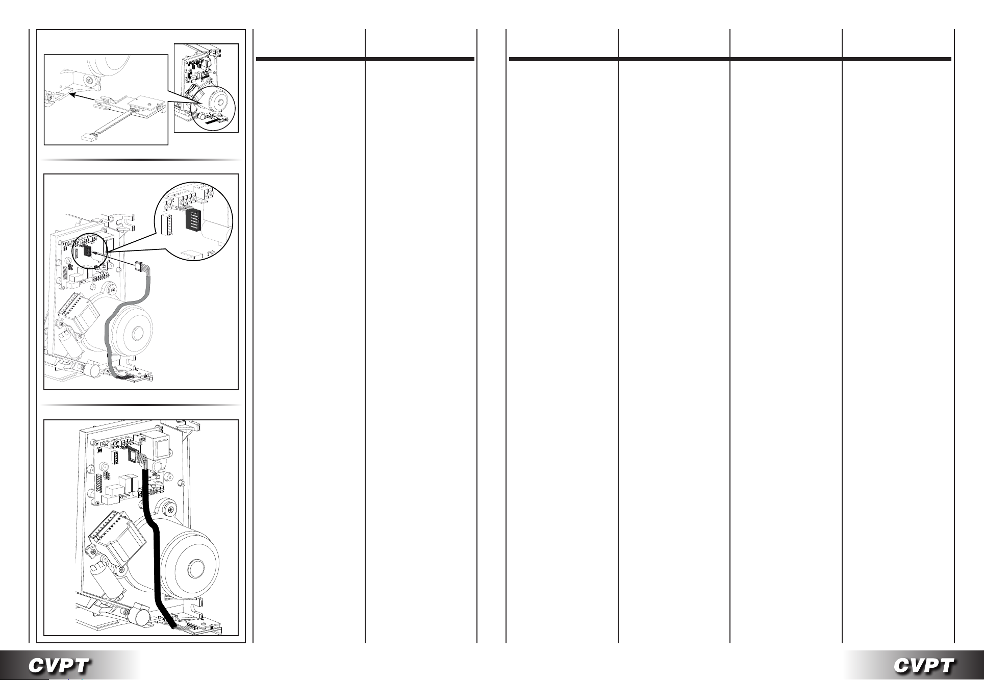
17 17A
M9
M
9
M
9
MONTAGGIO
DEL RICEVITORE
MOUNTING
THE RECEIVER
MONTAGE
DU RECEPTEUR
MONTAGE DES
EMPFANGSTEILS
MONTAJE
DEL RECEPTOR
MONTAGE
ONTVANGER
Fig./Abb.“1”
Fig./Abb.“2”
Fig./Abb.“3”
Fissare il ricevitore
come mostrato in Figura“1”.
Collegare il cavo del ricevitore
al connettore M9
identificato in Figura“2”.
Non si risponde
in caso di danni provocati
da modifiche o manomissioni
dell’apparecchio.
Fasten the receiver
as shown in Figure“1”.
Connect the receiver cable
to the M9 connector
identified in Figure“2”.
No liability is accepted
for damage
caused by modifications to
or tampering with the appliance.
Fixer le récepteur
voir Figure“1”.
Raccorder le câble du récepteur
au connecteur M9
identifié sur la Figure“2”.
La société ne répond pas
des dommages causés
par des modifications
ou détériorations de l’appareil.
Das Empfangsteilbefestigen,
wie aus der Abb.“1”ersichtlich.
Kabel des
Empfängers M9 anschließen;
siehe Abb“2”.
Der Hersteller haftet nicht
für solche Schäden, die durch
die Veränderung oder
die Manipulierung des Geräts
entstehen.
Fije el receptor
como indica la Figura“1”.
Conecte el cable del receptor
al conector M9
identificado en la Figura“2”.
La empresa no se hace
responsable en caso de daños
provocados por modificaciones
o manipulaciones del aparato.
Bevestig de ontvanger
,
zoals geïllustreerd
in Figuur“1”.
Sluit de kabel van de ontvanger
aan op de connector M9
aangegeven in Figuur“2”.
De fabrikant kan niet
aansprakelijk worden gesteld
voor schade veroorzaakt
door wijzigingen aangebracht
aan het apparaat.

CF MP
D1
T2
T1 T3
M8 M9
2
M9
M6
M4 M5
J3J2
E
V
3
N
M10
CVPT
Board
WH
OG
GN
C1
BK
RD
230V
YE
F2
P0 P0
10
0V
M7
M8
1
B1
PE
N
L
V
1
V
2
6 speed
M
M1
AT
M
50Hz
BK
BU
N
MC3
L
NNNN
21
J1
T2T1 T3 F2
N
PE
M1
M2
M3
LL
MC2
MC1
ON
GNYE
MP
230Vac 50Hz
T1
T2
T3
M2
Ricevitore/ Receiver
Récepteur / Empfänger
Receptor / Ontvanger
(OPTIONAL)
18 18A
AT = Autotrasformatore
C1 = Condensatore
D1 = Dip Switch
di configurazione
E = Elettrovalvola
T1 = Sonda aria (posta
in ripresa dell’apparecchio)
T2 = Sonda Change-Over
(optional)
T3 = Sonda di minima
M1= Motoventilatore
M2 = Motore Flap
M8 = Connettore Flap
M9 = Connettore
ricevitore infrarossi
CF = F2-F2 Contatto pulito
finestra aperta / presenza
persona.
Se aperto l’unità si ferma
MP = Pompa
di evacuazione consensa
AT = Autotransformer
C1 = Capacitor
D1 = Configuration dipswitches
E = Water valve
T1 = Air probe (fitted
at the appliance intake)
T2 = Change-Over probe
(optional)
T3 = Minimum probe
M1= Fan
M2 = Flap Motor
M8 = Flap Connector
M9 = Infra-red
receiver connector
CF = F2-F2 Window
open / person presence
voltage-free contact.
If open the unit stops
MP = Condensate pump
AT = Autotrasformateur
C1 = Condensateur
D1 = Dip Switch
de configuration
E = Électrovanne
T1 = Sonde air (placée
sur la reprise de l’appareil)
T2 = Sonde Change-Over
(option)
T3 = Sonde de temp. minimale
M1= Motoventilateur
M2 = Moteur Flap
M8 = Connecteur Flap
M9 = Connecteur
récepteur infrarouge
CF = F2-F2 Plot libre
fenêtre ouverte / détection
présence. S’il est ouvert
l’unité s’arrête
MP = Pompe d’evacuation
des condensats
AT = Spartransformator
C1 = Kondensator
D1 = Konfigurations-Dip-Switch
E = Elektroventil
T1 = Lufttemperaturfühler
(am Ansaugteil des Geräts)
T2 = Change-Over-Fühler
(Option)
T3 = Mindesttemperaturfühler
M1= Motorventilator
M2 = Flap-Motor
M8 = Flap-Anschluss
M9 = Anschluss
Infrarot-Empfänger
CF = F2-F2 Kontakt
offenes Fenster/Personal-
anwesen- heit. Wenn offen,
schaltet sich das Gerät aus
MP = Kondensatpumpe
AT = Autotransformador
C1 = Condensador
D1 = Dip Switch
de configuración
E = Electroválvula
T1 = Sonda aire (colocada en
reanudación del aparato)
T2 = Sonda Change-Over
(opcional)
T3 = Sonda de mínima
M1= Motoventilador
M2 = Motor Flap
M8 = Conector Flap
M9 = Conector
receptor infrarrojos
CF = F2-F2 Contacto limpio
ventana abierta / presencia
persona. Si está abierto
la unidad se para
MP = Bomba de evacuación
de condensados
AT = Autotransformator
C1 = Condensator
D1 = Dimschakelaar configuratie
E = Elektromagnetische
T1 = Luchtsonde
(vlakbij het apparaat)
T2 = Sonde Change-Over
(optie)
T3 = Minimumsonde
M1= Motorventilator
M2 = Flapmotor
M8 = Flapconnector
M9 = Connector
infraroodontvanger
CF = F2-F2 Schoon contact
open raam / aanwezigheid
persoon. Indien open stopt
de eenheid
MP = Condensatwaterpomp
SCHEDA
ELETTRONICA
ELECTRONIC
BOARD
CARTE
ELECTRONIQUE
ELEKTRONIK-
PLATINE
TARJETA
ELECTRÓNICA
ELEKTRONISCHE
FICHE
LEGENDA: KEY: LÉGENDE: LEGENDE: LEYENDA: LEGENDE:

CF
MC2
BK
GY
MC1
MP
FUNZIONE
DEI CONTATTI
AUSILIARI
FUNCTION
OF THE AUXILIARY
CONTACTS
FONCTION
DES CONTACTS
AUXILIAIRES
FUNKTION
DER
HILFSKONTAKTE
FUNCIONES
DE LOS CONTACTOS
AUXILIARES
FUNCTIE
VAN DE
HULPCONTACTEN
ContattoCF(F2-F2):
- contatto finestra aperta
- sonde presenza persona
- un altro sistema
A contatto chiuso
l’apparecchio funziona.
A contatto aperto
l’apparecchio si ferma.
Se utilizzato,
togliere il Jumper MC2
di chiusura del contatto.
ContattoMP(Po-Po):
Contattoallarmepompa
dievacuazionecondensa
Se utilizzato,
togliere il Jumper MC1
di chiusura del contatto.
Per il montaggio della pompa
di evacuazione condensa
vedere pagina 53.
Eseguire
i collegamenti come
da schema elettrico (Pag. 32).
Contattodell’allarme:
BK = Nero
GY = Grigio
19 19A
ContactCF(F2-F2):
- window open contact
- person presence sensors
- other systems
When the contact is closed
the appliance can operate.
When the contact is openthe
appliance is stopped.
If used,
remove the MC2 Jumper
for contact closure.
ContactMP(Po-Po):
Alarmswitch
condensationpump
If used,
remove the MC1 Jumper
for contact closure.
See page 53 to assemble
the condensate pump.
Make
the connections as indicated
in the wiring diagram (page 32).
Alarmswitch:
BK = Black
GY = Grey
ContactCF(F2-F2):
- contact fenêtre ouverte
- sonde détection de présence
- autre système
Contact fermé
l’appareil fonctionne.
Contact ouvert
l’appareil s’arrête.
Si utilisé,
enlever le cavalier MC2
de fermeture du contact.
ContactMP(Po-Po):
Contactd’alarmedelapompe
d’evacuationdescondensats
Si utilisé,
enlever le cavalier MC1
de fermeture du contact.
Pour le montage de la pompe
d'évacuation de la condensation,
voir la page 53.
Effectuer
les branchements en suivant
le schéma électrique (Page 32).
Contactd’alarme:
BK = Noir
GY = Gris
KontaktCF(F2-F2):
- Kontakt für offenes Fenster
- Personalanwesenheitsmelder
- anderem System
Bei geschlossenem Kontakt
funktioniert das Gerät.
Bei offenem Kontakt schaltet
sich das Gerät aus.
Falls verwendet, ist der
Jumper MC2 für den Verschluss
des Kontakts zu entfernen.
KontaktMP(Po-Po):
Alarmschalter
kondensatpumpe
Falls verwendet, ist der
Jumper MC1 für den Verschluss
des Kontakts zu entfernen.
Zur Montage der Kondensat-
Evakuierungspumpe
siehe S. 53.
Anschlüsse gemäß
Schaltplan vornehmen (S. 32).
Alarmschalter:
BK = Schwarz
GY = Grau
ContactoCF(F2-F2):
- contacto ventana abierta
- sonda presencia persona
- otro sistema
Con el contacto cerrado
el aparato funciona.
Con el contacto abierto
el aparato se para.
Si se ha utilizado,
quitar el Jumper MC2 de cierre
del contacto.
ContactoMP(Po-Po):
Contactodealarmadelabomba
deevacuatióndecondensados
Si se ha utilizado,
quitar el Jumper MC1 de cierre
del contacto.
Para montar la bomba
de evacuación de condensados
consulte la página 53.
Realice las conexiones
como se indica en el esquema
eléctrico en la (Pág.32).
Contactodelaalarma:
BK = Negro
GY = Gris
KontaktCF(F2-F2):
- contact open raam
- sonde aanwezigheid persoon
- ander systeem
Bij gesloten contact werkt
het apparaat.
Bij open contact stopt
het apparaat.
Verwijder, indien gebruikt,
de Jumper MC2 voor
het afsluiten van het contact.
KontaktMP(Po-Po):
AlarmKontakt
condenswaterpomp
Verwijder, indien gebruikt,
de Jumper MC1 voor
het afsluiten van het contact.
Voor de montage van
de pomp voor condensevacuatie
raadpleegt men pagina 53.
De aansluitingen
volgens het elektrische schema
uitvoeren (pag. 32).
Alarmkontakt:
BK = Zwart
GY = Grijs

Prima di effettuare qualsiasi
operazione con il telecomando,
inserire le batterie a corredo.
Le batterie
che devono essere utilizzate
sono di tipo AAA 1,5 Volt.
Before performing any operations
with the remote control,
insert the batteries supplied.
Type AAA 1.5 Volt batteries
must be used.
Avant toute opération
avec la télécommande mettre
les piles fournies.
Utiliser des piles
de type AAA 1,5 volt.
Bevor die Fernbedienung benutzt
wird, müssen die mitgelieferten
Batterien eingesetzt werden.
Die zu verwendenden Batterien
sind vom Typ AAA 1,5 Volt.
Antes de realizar cualquier ope-
ración con el mando a distancia,
insertar las baterías adjuntas.
Las baterías
que se tienen que usar
son del tipo AAA 1,5 Volt.
Alvorens de afstandsbediening
te gebruiken, worden de
bijgeleverde batterijen geplaatst.
Gebruik batterijen
van het type AAA van 1,5 Volt.
NON DISPERDERE
LE BATTERIE
NELL’AMBIENTE.
UTILIZZARE GLI APPOSITI
CONTENITORISMALTITORI.
DISPOSE OF THE BATTERIES
PROPERLY, USING
THE PROPER
WASTECONTAINERS.
NE PAS ABANDONNER
LES PILES DANS LA NATURE,
ET UTILISER
LES CONTENEURS SPÉCIAUX
POUR LA RÉCUPÉRATION
DES DÉCHETSTOXIQUES.
BATTERIEN IN DIE
DAFÜR VORGESEHENEN
ABFALLEIMERWERFEN.
DE BATTERIJEN
NIET IN HET MILIEU
ACHTERLATEN; GEBRUIK
DE SPECIALE AFVALBAKKEN
VOORDEVERWERKING.
NO ABANDONAR
LAS BATERÍAS
EN EL MEDIO AMBIENTE,
UTILIZAR
LOS CONTENEDORES
ADECUADOS.
20 20A
BATTERIE BATTERIES PILES BATTERIEN BATERÍAS BATTERIEIEN
Table of contents


