7
On/Off Switch
The ON/OFF switch supplies and disconnects power to the HRV control board.
When positioned in the ON position, this switch will illuminate. The switch will
not illuminate if the power supply is disconnected or the switch is turned to the
OFF position.
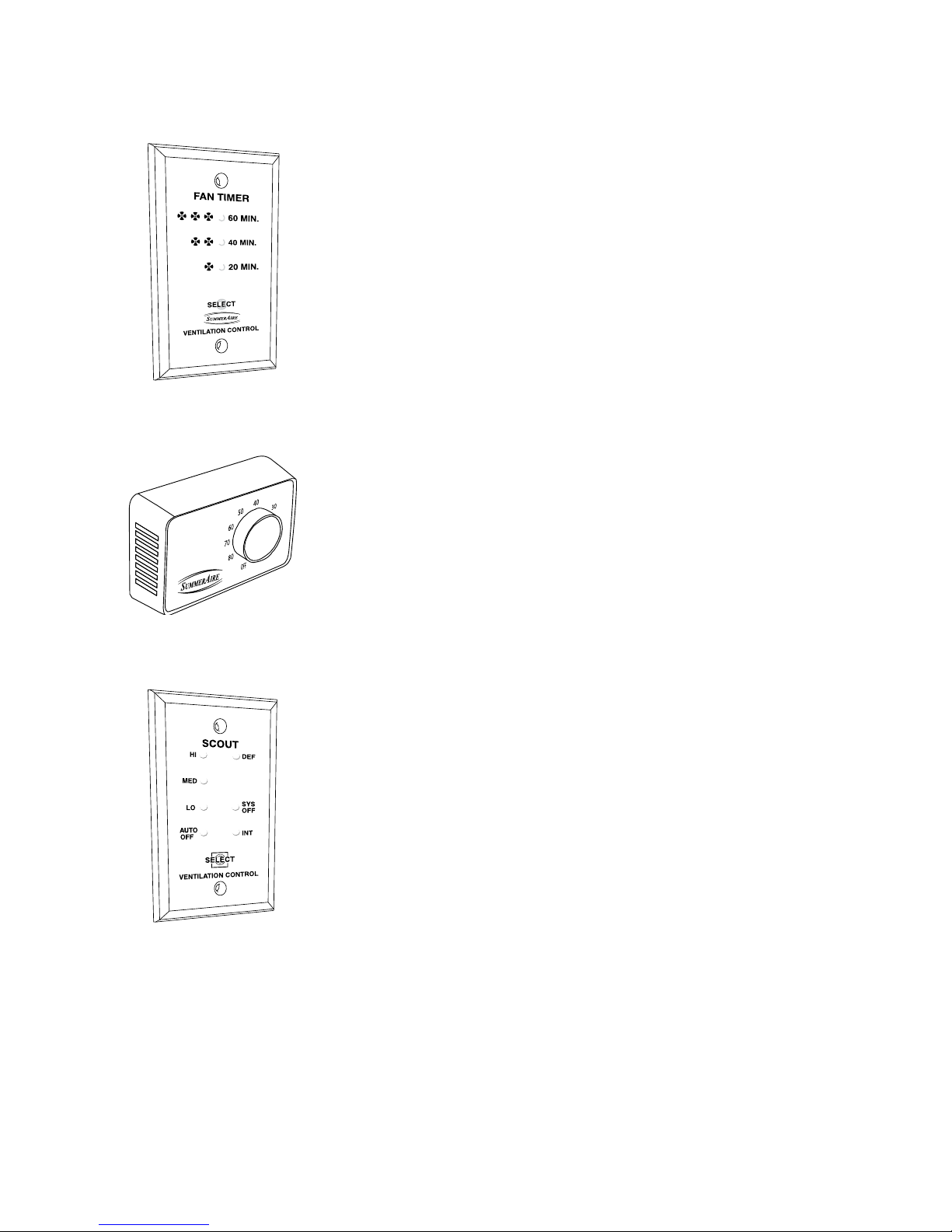
Option Select Button
By depressing the SELECT button momentarily, you can select low, medium or
high ventilation fan speeds, as well as the AUTO/OFF or SYSTEM OFF modes.
The selection will be indicated by the illumination of the respective LED on the
HRV display panel.
Auto/Off
When this mode of operation is selected, the HRV ventilator fan will be turned
off until activated by the internal dehumidistat or an optional external control
such as a Wall Mount Dehumidistat, Wall Switch, Touch Pad Timer, Scout,
Watchman or Sentinel control. This selection is displayed by the continuous
illumination of the Auto/Off LED on the HRV, SCOUT, WATCHMAN and
SENTINEL controls. When the fan is activated automatically or manually at
a Touch Pad, it will be indicated by the ashing On and Off of the High-speed
indicator on the control panels.
High Speed Flashing
When the internal dehumidistat or an external control has activated the HRV
to high speed, the High Speed LED light will illuminate and ash. If you have
already selected one of the ventilation speeds as discussed in the previous
section “Option Select Button”, and the High Speed has been activated, then
you will see both the continuously lit LED for the fan speed selection and the
high speed LED ashing. Once the device initiating the high speed cycle has
been satised, the HRV control fan will reset to the pre-selected mode and the
ashing High Speed LED will turn off.
Summer / Winter Switch
This switch must be positioned in the summer position when the optional
summer core is installed in the HRV. This will cause the HRV to shut down
should the air temperature entering the HRV fall below -15°C (5°F). This
prevents permanent damage to the core. Position this switch to winter when
the winter core is used to ensure correct operation during colder periods.