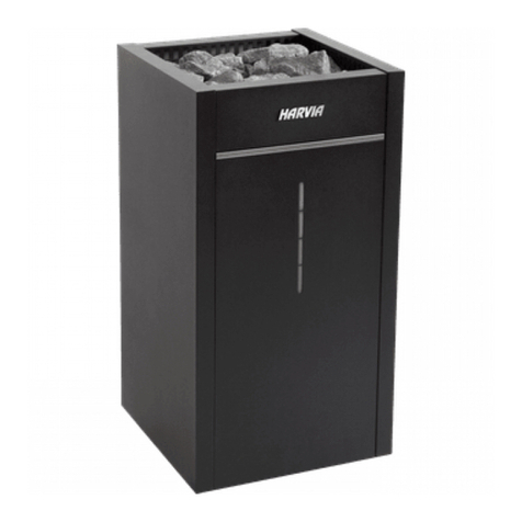
HEATpool Titan Series User manual

HEATpool
ELEKTRICKÝ PRŮTOKOVÝ OHŘÍVAČ VODY HEATpool Titan
THE ELECTRIC FLOW WATER HEATER OF THE HEATpool Titan TYPE
ELEKTRISCHER DURCHLAUFWASSERERHITZER TYPE HEATpool Titan
ЭЛЕКТРИЧЕСКАЯ ВОДОГРЕЙНАЯ КОЛОНКА НЕПРЕРЫВНОГО ДЕЙСТВИЯ ТИП HEATpool Titan
HEATpool - TITAN ELECTRIC HEATERS

HEAT pool TITAN electric flow unit assembly instructions
Before starting the assembly:
Carefully study all instructions for installation and make sure that you understand these.
SAFETY MEASURES
•Electrical connection must be made by a qualified professional with appropriate certification.
Warranty cannot be settled positively without submitting invoice for professional connection.
•Installation must be in compliance with electrical standards applicable in the country where
installation is performed.
✓Heater’s electrical source must always be protected in the beginning of the circuit with a
residual current device with switch-off current Ir = 30mA, which protects persons against injury
caused by hazardous current.
✓Disconnect the device from electric voltage before starting any activities
✓Install the electric heater in a place inaccessible to the public.
✓It is necessary to use a feedback with the filtration pump.
✓HEATpool –TITAN is also suitable for pools with water treatment using salt water as well as
sea water.
✓HEATpool TITAN heaters are always pre-connected for connection to three-phase source 400
V ~ 50 Hz or single-phase 230 V ~ 50 Hz; (see the viz. «Electric connection» section)
Content of the box
The box must contain the following:
✓Electric heater HEATpool –TITAN with electrical flow flap
✓Electric control box with digital thermostat, which is connected to the heater by a flexible
insulation tube
✓Holders for wall mounting –2 pcs
✓Instructions for installation and use
MARKING AND CHARACTERISTICS OF YOUR HEATER
Marking
before installing the heater, determine the model according to its marking.
Example:
EOV H 12 Ti
EOV Electric water heater
H Type: HEAT pool
12 12 kW
Ti Titanium
Heater dimensions

3kW 6kW 9kW 12kW
a 330 mm 410 mm 520 mm 700 mm
Technical parameters
output 3kW 6kW 9kW 12kW
material Titan Titan Titan Titan
input upon 1-phase connection 13A 26A 40A
type of cable upon 1-phase
connection 3x4 3x6 3x10
input upon 3-phase connection 4,5A 9A 14A 17A
type of cable upon 1-phase
connection 5x2,5 5x2,5 5x4 5x4
Connection 50mm 50mm 50mm 50mm
Min. flow rate 4m3/h 4m3/h 4m3/h 4m3/h
Max. flow rate
INSTALLATION
Hydraulic connection
The electric heater must be connected to the displacement circuit after the filter - see fig. 1, before
the chemical treatment section (dosage pump, semi-automatic chlorinator, electrolyzer, etc.). The
heater is recommended to be installed 0,5-2m under the water level. “By-pass” installation is
recommended with the objective of simplifying potential operations on the heater and its
preparation for winter. By-pass must be connected always in the direction of under the existing
pipes, so that the heating unit cannot be aerated. Upon direct installation in the pipe, it is necessary
to install heating under the water circuit level, i.e. „U“-type connection –see fig. 1. This installation
secures permanent irrigation of the heating cartridge. When selecting a suitable place for
installation, it is recommended to count on a configuration enabling extraction of the heating unit,
without taking the heater out of the hydraulic circuit. It is necessary to secure laminar (streamline)
flow, i.e. through a straight pipe at least 50cm in the direction of water flow before the heating.
After installation, the connection must be tested.
HEATpool - TITAN heaters are equipped with detachable connection to water circuit, enabling
easy handling if necessary.


✓Cables used for the installation of the length of up to 20 m are cables with 5 conductors (3
phases + protective conductor + grounding conductor) (5x2,5 mm² for 3 and 6kW heaters and
5x4 mm² for 9 and 12kW heaters.
✓Grounding conductor (green & yellow) must be connected to the grounding terminal marked
with the symbol (┴).
✓Protective conductor (blue) must be connected to the second blue terminal marked with the
letter (N).
✓Phase conductors (other colours) must be connected on grey terminals marked with letter
(……).
Electric heating controls switchboard
PE NPo
1 3 5 13 A1
2 4 6 14 A2
K1
PŘÍVODNÍ KABEL 5 x 2,5 (5 x 4) mm2
modrý
zele nožl utý
ROZVADĚČ OVLÁDÁNÍ ELEKTRICKÉHO TOPENÍ
3 4
1R1
KABEL 2 x 0,75 mm2
Cable Intake cable

1 2
3 4
5 6
N N
1K1
EOV
QFU
Po
1ET
TP PK
K1
1
2
3
4
5
6
A1
A2
1
2
1 2
TT - topné těleso
Q - proudový chránič FI 30mA
FU - jistič
ET - regulační termostat
TP - tepelná pojistka
PK - průtoková klapka
K1 - stykač
TT
EOV - elektrický ohřev
L1
L2
L3
PE
NPE
N
TYP : EOV
13
14 7
8ET
V1
Po - ovládací pojistka
V1 - vypínač topení
1R1
3 4
1R1 - kontakt stykače filtrace
EOV = electric heating TP = thermal fuse
TT = heating unit PK = flow flap
Q = residual current device K1 = contactor
FU = fuse Po = control fuse
ET = regulation thermostat V1 = heating switch
1R1 = filtration contactor contact

For single-phase 3 and 6 kW heaters
✓Cables used for the length of pipe of up to 20 m are cables with 3 conductors (phase +
protective conductor + grounding conductor) (3x4 mm² for 3 kW heaters and 3x6 mm² for 6 kW
heaters.
✓Grounding conductor (green & yellow) must be connected to grounding terminal marked with
the symbol (┴).
✓Protective conductor (blue) must be connected to the second blue terminal marked with letter
(N).
✓Phase conductor (other colour) must be connected to the first grey terminal marked with letter
(P).
► Double connection coupler must always be installed between 2 blue terminals marked with
the letter (N).
► Triple connection coupler must always be installed between 3 grey terminals marked with
the letter (P).
Electric heating controls switchboard
PENPo
1 3
A1
2 4
A2
K1
PŘÍVODNÍ KABEL 3 x 2,5 (3 x 4) mm2
modrý
zele nožl utý
ROZVADĚČ OVLÁDÁNÍ ELEKTRICKÉHO TOPENÍ
3 4
1R1
KABEL 2 x 0,75 mm2
L
černý
Cable Intake cable

For single-phase 9 kW heaters
✓Cables used for the length of pipe of up to 20 m are cables with 3 conductors (phase +
protective conductor + grounding conductor) (3x10 mm²)
✓Grounding conductor (green & yellow) must be connected to the grounding terminal marked
with the symbol (┴).
✓Protective conductor (blue) must be connected to the second blue terminal marked with the
letter (N).
✓Phase conductor (of another colour) must be connected to the first grey terminal marked with
the letter (P).
Electric heating controls switchboard
PENPo
PŘÍVODNÍ KABEL 3 x 10 mm2
modrý
zele nožl utý
ROZVADĚČ OVLÁDÁNÍ ELEKTRICKÉHO TOPENÍ
3 4
1R1
KABEL 2 x 0,75 mm2
L
černý
1 3 5 13 A1
2 4 6 14 A2
K1
Cable Intake cable

1K1
EOV
QFU
Po
1ET
TP PK
K1
1
2
3
4
5
6
A1
A2
1
2
1 2
TT - topné těleso
Q - proudový chránič FI 30mA
FU - jistič
ET - regulační termostat
TP - tepelná pojistka
PK - průtoková klapka
K1 - stykač
TT
EOV - elektrický ohřev
L1
PE
NPE
N
TYP : EOV
13
14 7
8ET
V1
Po - ovládací pojistka
V1 - vypínač topení
1R1
3 4
1R1 - kontakt stykače filtrace
L1
EOV = electric heating TP = thermal fuse
TT = heating unit PK = flow flap
Q = residual current device K1 = contactor
FU = fuse Po = control fuse
ET = regulation thermostat V1 = heating switch
1R1 = filtration contactor contact

Switching filter feedback on
Filter feedback must be switched on using a cable of grey terminals marked with the letter (P) to an
auxiliary switching contact of filtration contactor. A cable with two conductors of the cross-section
of 1,5 mm² is used.
Cable inlet in the heater box is sealed in a cable bushing.
USE
Commissioning
Check if the electrical connection is established and operational, then start the filtration pump and
press the switch on the front side of the box (move it upward).
Setting-up the thermostat
Digital thermostat is to be set up using the following procedure to a higher value than the
current water temperature.
a) Set-up parameters:
□ Instruction (°C): Required water temperature.
□ Hy = Tolerance (°C), range of the required temperature around the instruction. The smaller the
value, the more frequent turning on of the heater, and water temperature more exact. It is factory-set
to 2 °C.
Example
* Instruction = 26 °C, tolerance = 2 °C (factor setting), temperature measured = 24°C.
Heating required, set-up operational. It stops as soon as the temperature being measured is equal to
26+2 = 28°C (instruction + tolerance).
b) Opening instruction set-up:
▲▼ 1 – Press and release the SET button: instruction set-up value is shown
■ 2 –Press and release the SET button or wait 5 seconds: the temperature being measured is
shown again.
c) How to change instruction set-up:
▲▼ 1 –Press the SET button and hold for 2 seconds
2 –The value of instruction set-up is shown and the LED * flickers
■3 –Change the instruction set-up value by buttons ▲ or ▼.
4 –In order to save the new instruction value, press again the SET button or wait for 10
seconds.
d) How to change the tolerance value:
LED: 1 –Enter the programming mode by simultaneously pressing
the following buttons: „SET“ +▼ and holding these for 3 seconds.
2 –(LED 1 and * flicker). Hy is shown.
3 –Press the „SET“ button (the shown Hy value flickers).
4 –To change this value, use the buttons ▲or▼.
5 –To save this new value, press the “SET” button.
Exiting: press „SET“ +▼ or wait 15 seconds.
Note: the new value is saved in both cases.
For classic use, set up the tolerance value to 1.

Control measures
The heater is already operational, check if the heater switches off in the following cases:
- filtration pump stops
- water flow to heater intake stops
- thermostat instruction interrupted
Safety thermostat
HEATpool –TITAN heaters are equipped with a safety thermostat limiting temperature to max. 54-
60oC for manual control.
Activities within the frame of the warranty shall not extend the warranty.
The only obligation that follows to the seller from the warranties free of charge is replacement or
repair of the product or part, which the seller’s servicing organisation identified as defective. Other
costs are covered by the buyer.
Warranty acknowledgement requires that each product must first go through seller’s warranty
service, whose approval is a precondition for any replacement.
ADVICE FOR USE AND SAFETY MEASURES
✓Upon the first operation of heating or during the beginning and end of the pool season it is
recommended to start permanent operation so that the heater can increase pool temperature
more easily. During the season, or when energetic requirements are smaller, filtering may be run
in automatic regime.
✓Use of isometric cover material (bubble foil, sliding cover, foam cover) is recommended to
reduce electric power consumption by the heater and to optimise heating.
✓If the pool is filled with calcareous water, it is recommended to regularly check for presence of
limescale in the heating elements. Possibly use a tester for water hardness and then treat the
water by adding chemicals to decrease water hardness. Further, it is possible to use magnetic
treatment.
✓Disassembly of the heater head must be carried out by a professional within the frame of a
potential repair.
✓Preparation of heater for winter: disconnect main supply of electric power and disconnect the
electric power box cable. Empty the heater body by unscrewing the connecting fitting.
Warranty
HEATpool –TITAN heaters have a warranty for all material defects and manufacture defects
during 24 months from the date of installation.
This warranty does not cover wear and tear of parts.
Defects and damage caused by incorrect installation are also exempt from the warranty
Positive settlement of warranty claim is conditioned by observing instructions for use and
installation. By documenting a confirmed hand-over protocol or warranty certificate with a date of
commissioning. The warranty does not cover the cases of failure to fulfil these conditions and
especially the following cases:
- Electrical connections were not performed by a professional.
- One of the safety features or parts of controls was disabled or bridged.
- Upon accumulation of scale on the heating unit
This manual suits for next models
4
Table of contents
