Clockaudio CDT100 User manual
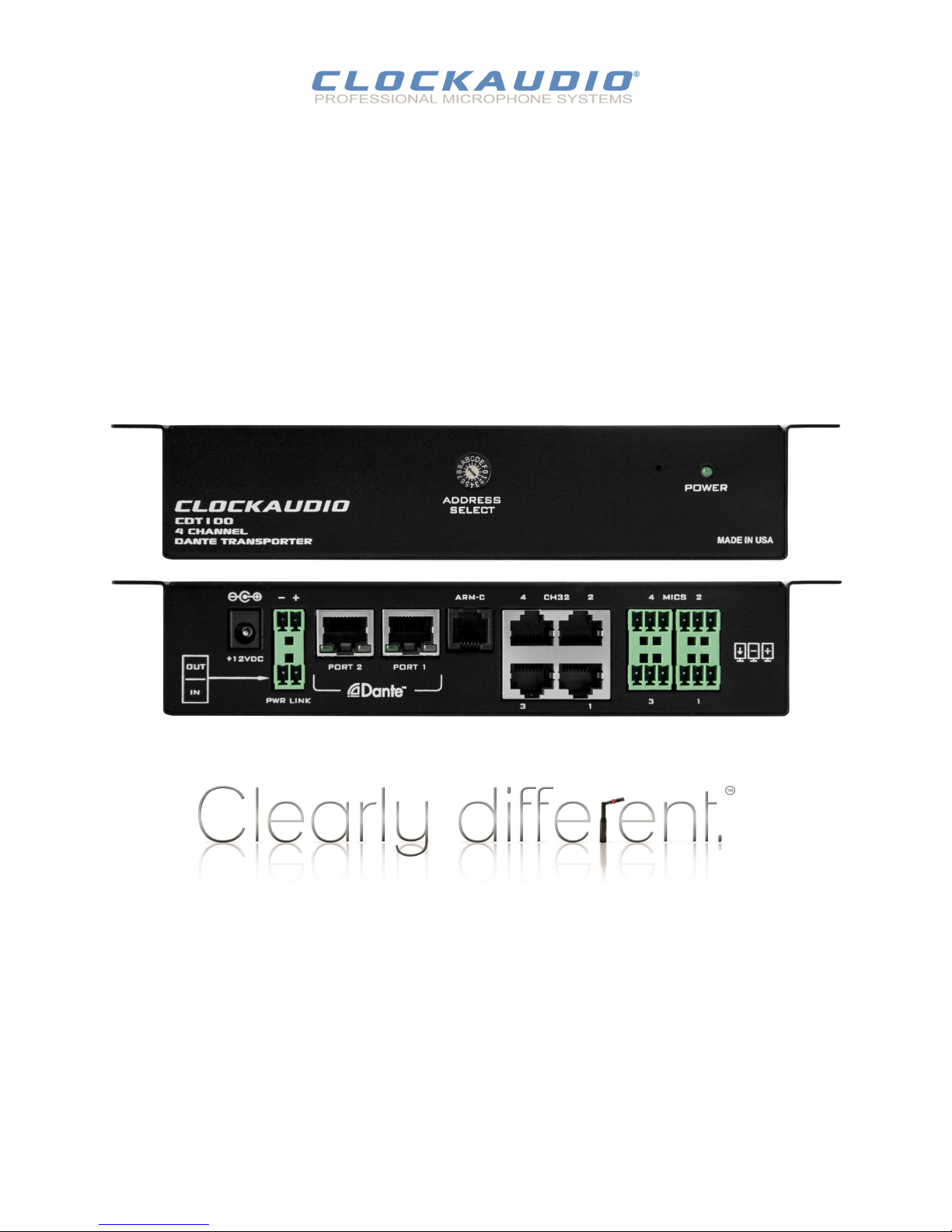
CDT100
Clockaudio Dante Transporter
Four analog and control inputs to Dante enabled endpoint
User Manual
© Clockaudio 2015
Clockaudio Ltd.
Address: 22 Arnside Road, Waterlooville, Hampshire, PO7 7UP
Tel: +44(0)23 9225-1193 Fax: +44(0)23 9225 1201
Email: info@Clockaudio.co.uk
Clockaudio North America Inc.
Address: 2891, du Meunier, Unit 103, Vaudreuil-Dorion, QC, Canada J7V 8P9
Toll Free: 1-888-424-9797 Tel: 888-424-9797 Fax: 450-424-3660
Email: www.clockaudio.com
CDT100 User Manual
Clockaudio PTE Ltd.
Address: BizTech Centre, Unit # 01-02, 627A Aljunied Road, Singapore, 389842
Tel: +65 67484738 Fax: +65 67484428
Email: info@clockaudio.com.sg
2
1. Read these instrucons.
2. Keep these instrucons.
3. Heed all warnings.
4. Follow all instrucons.
5. Do not use this apparatus near water.
6. Clean only with a dry cloth.
7. Do not block any venlaon openings. Install in accordance with the manufacturer's instrucons.
8. Do not install near any heat sources such as radiators, heat registers, stoves, or other apparatus (including ampliers) that
produce heat.
9. Do not defeat the safety purpose of the polarized or grounding-type plug. A polarized plug has two blades with one wider
than the other. A grounding type plug has two blades and third grounding prong. The wider blade or the third prong is
provided for your safety. If the provided plug does not t into your outlet, consult an electrician for replacement of the
obsolete outlet.
10. Protect the power cord from being walked on or pinched parcularly at plugs, convenience receptacles, and the point
where they exit from the apparatus.
11. Only use aachments/accessories as specied by Clockaudio.
12. Use only with the bracket specied by the manufacturer.
13. Refer all servicing to qualied service personnel. Servicing is required when the apparatus has been damaged in any way,
such as power-supply cord or plug is damaged, liquid has been spilled or objects have fallen into the apparatus, if the ap-
paratus has been exposed to rain or moisture, does not operate normally or has been dropped.
14. This apparatus shall be connected to a mains socket outlet with a protecve earthing connecon.
15. If rack mounng, provide adequate venlaon. Equipment may be located above or below this apparatus but some
equipment (like large power ampliers) may cause an unacceptable amount of hum may generate too much heat and
degrade the performance of this apparatus.
This symbol, wherever it appears, alerts you to the presence of un-insulated dangerous voltage inside the enclosure -
voltage that may be sucient to constute a risk of shock.
This symbol, wherever it appears, alerts you to important operang and maintenance instrucons in the accompanying
literature. Please read the manual
TO REDUCE THE RISK OF FIRE OR ELECTRIC SHOCK, DO NOT EXPOSE THIS APPARATUS TO RAIN OR MOISTURE.
© Clockaudio 2015
IMPORTANT SAFETY INSTRUCTIONS
The symbols below are internaonally accepted symbols that warn of potenal hazards with electrical products.
CDT100 User Manual

3
LIMITED ONE YEAR WARRANTY
The equipment is warranted for one year from date of purchase from Clockaudio against defects in materials or workmanship.
This warranty does not cover equipment which has been abused or damaged by careless handling or shipping.
This warranty does not apply to used or demonstrator equipment.
Should any defect develop, Clockaudio will, at our opon, repair or replace any defecve parts without charge for either parts or
labor.
If Clockaudio cannot correct the defect in the equipment, it will be replaced at no charge with a new item. Clockaudio will pay
for the cost of returning the replacement equipment to you.
This warranty applies only to items returned to Clockaudio, shipping costs prepaid, within one year from the date of
purchase.
Note:
This equipment has been tested and found to comply with the limits for a Class A digital device,
pursuant to Part 15 of the FCC Rules and EN55022.
These limits are designed to provide reasonable protecon against harmful interference when
the equipment is operated in a commercial environment.
This equipment generates, uses, and can radiate radio frequency energy and, if not installed
and used in accordance with the instrucon manual, may cause harmful interference to radio
communicaons.
Operaon of this equipment in a residenal area is likely to cause harmful interference, in
which case the user will be required to correct the interference at his own expense.
© Clockaudio 2015
CDT100 User Manual

4
Contents
OVERVIEW ....................................................................................................................................................................................................
DEVICE FEATURES ......................................................................................................................................................................................
CONNECTIONS.............................................................................................................................................................................................
3.1 – Input from a Balanced Source..........................................................................................................................7
3.2 – Input from an Unbalanced Source ...................................................................................................................7
4 – DEVICE CONFIGURATION ........................................................................................................................................8
4.1 – IP Address Setup .............................................................................................................................................8
4.2 – Device Idencaon ........................................................................................................................................9
5 – DANTE DAISY CHAINING .................................................................................................................................10
5.1 – Daisy Chain Illustraon - Example 1...............................................................................................................11
5.2 – Daisy Chain Illustraon - Example 2...............................................................................................................12
6 – MOUNTING.....................................................................................................................................................13
7 – CONTROL MODULES .......................................................................................................................................14
7.1 – Crestron .........................................................................................................................................................15
7.2 – AMX................................................................................................................................................................16
4 – ARCHITECT SPECIFICATIONS ...........................................................................................................................17
© Clockaudio 2015
CDT100 User Manual
5
1 - Overview
The CDT 100 four input Dante interface is the ideal interface for adding mic inputs to a Dante system.
The small form factor to the CDT 100 allows them to be mounted almost anywhere, pung them close to the microphone
sources and minimizing interference-prone analog wiring.
CDT 100 Features:
Easy to install with under table mounng.
Audio and control signals transported over Dante.
4 X mic/line inputs using 3-pin de-pluggable connectors for “Balanced” or “Unbalanced” connecvity.
Provides phantom power for each input also supports a +48V phantom power opon.
Powered by an external +12VDC (ordered separately).
Power can also be daisy chained
The CDT 100 has 4 X connecons to support the CH32 buon and other Clockaudio control devices:
CRM 202S
CS S Series
S 80S
SM 80S
TS001
The CDT 100 connects directly to ARM-C port for the ARM motorized microphone.
The CDT 100 has two network connecons to allow Dante Daisy Chaining (DDC).
DDC further simplies system infrastructure wiring by allowing mulple CDT100’s to use a single CAT 5 home run connecon
to a network switch.
Compable with any Dante capable audio DSP.
The CDT 100 can be controlled and monitored with 3rd party control soware using direct UDP messages.
Figure 1 - CDT100 front and back panel
© Clockaudio 2015
CDT100 User Manual
6
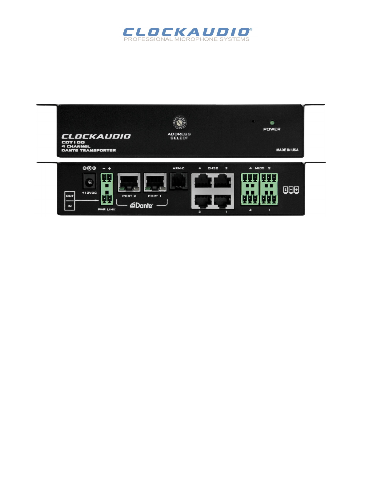
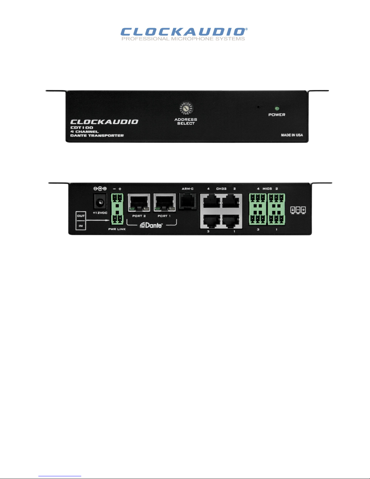
2 – Device Features
Figure 2 - CDT100 front panel
Power LED.
Reset Buon (recessed not visible).
Address Select.
4 Balanced audio inputs with phantom power, mulple units may be daisy
chained.
4 X CH32 control inputs. Connects directly to CH32 Litetouch and other
Clockaudio control devices.
ARM-C controller direct connecon.
2 X Dante Ethernet interface connector and indicators.
Daisy chain power input and output.
Power Socket - Use with oponal 12V DC supply only.
© Cockaudio 2015
CDT100 User Manual
Figure 3 - CDT100 back panel
7
CDT 100
+
Source
+
-
unDIO2x2
Input
Shield
-
CDT100 User Manual
© Clockaudio 2015
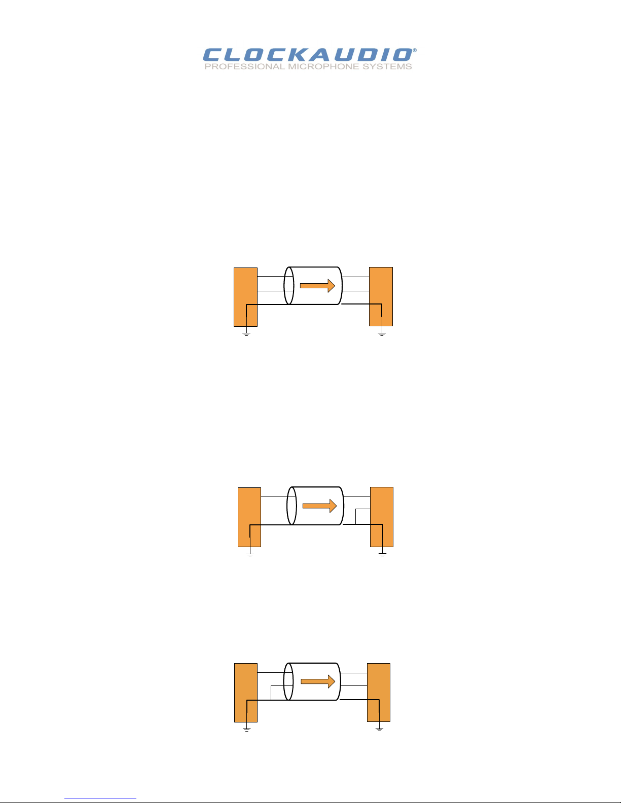
Figure 4 - Balanced Source Connecon
-
To connect balanced sources to the CDT 100:
Connect posive output to posive input, negave output to negave input
Connect the grounds together through the cable shield.
The CDT 100 accepts unbalanced or balanced audio devices.
Refer to the following diagrams and instrucons for connecng dierent types of audio devices.
Professional grade audio cabling is recommended to achieve the best audio performance throughout the system.
To connect a 2-wire unbalanced source to the CDT 100:
Connect the posive output of the unbalanced source to the posive input of the CDT 100.
Connect both the source and CDT 100 input grounds together
Short the negave input of the CDT 100 to ground at the input of the CDT 100.
+
Source
+
-
unDIO2x2
Input
Shield
CDT 100
Figure 5 - 2-Wire Unbalanced Source Connecon
To connect a 3-wire unbalanced source to a CDT100:
Short the negave conductor to the shield at the source connecon.
+
Source
+
-
Shield
unDIO2x2
Input
CDT 100
Figure 6 - 3-Wire Unbalanced Source Connecon

8
In order to congure an CDT100 both to set up its internal parameters and also setup audio roung, the PC will need to be able
to communicate with it over the network.
While all Dante devices will be discovered regardless of the IP address setup on the PC, communicaon can only occur if the PC
and the device have compable IP addresses.
By default, CDT100 is set to get a dynamic IP address. As with all Dante devices, if the CDT100 device does not nd a DHCP server
to retrieve an IP address from, it will give itself an automac private IP address (APIPA) instead.
An APIPA is always in the range 169.254.x.y.
To ensure communicaon, the PC can either be set to get a dynamic IP address, or be given a stac IP address in the range
169.254.x.y. The PC may require a restart for the changes to take aect.
Further informaon on IP setup for an audio system using Dante can be found in the FAQ’s on the Audinate website
(hps://www.audinate.com/resources/faqs).
CDT100 User Manual
© Clockaudio 2015
There are two parts of the device that require soware to setup:
1. The audio roung.
2. The congurable features of the device itself.
The audio roung should be carried out using Audinate’s Dante Controller, available for Windows and Mac OS X from the Audinate
website www.audinate.com along with instrucons on how to use the soware and seng up routes on a Dante network.
Dante Controller is a free soware applicaon that enables you to route audio and congure devices on a Dante network.
With automac device discovery, one-click signal roung and user-editable device and channel labels.
See the overview link for more details on Dante audio networking.
4.1 - IP Address Setup
Important Notes:
When using Dante controller, the CDT100 will be shown using a default device name of CDT100-###### where ‘######’ is the
last six characters of the devices MAC address.
Failure to correctly congure IP addresses will not allow an CDT100 device to correctly authencate in the soware and while it
will show up in Dante Controller. The input and output channels won’t be visible and roung of audio to and from the CDT100
will not be possible.
Features:
View all Dante-enabled audio devices and their channels on the network..
View and edit device clock and network sengs
Route audio between devices, and view the state of exisng audio routes
Rename devices and channels using your own friendly names
Customize the receive latency (latency before playout)
Save and reapply audio roung presets
Edit presets oine, and apply as conguraons for new network deployments
Change sample rates and clock sengs
View mulcast bandwidth across the network
View transmit and receive bandwidth for each device
View device performance informaon, including latency stats, clock stability stats and packet errors
View comprehensive, congurable event logs

9
4.2 – Device Idencaon
The device idencaon feature allows the user to see which device is physically being congured.
When the idenfy feature is acve, the power LED on the acve device will ash.
The Idenfy check box shows the state of the device idenfy feature. If the box is checked, the feature is acve on the acve unit.
If the check box is clear, the idenfy feature is inacve.
To change the state of the feature, simply click in the Idenfy check box to toggle its state from o to on or on to o.
The idenfy funcon will connue to operate unl the funcon is turned o via the user interface or the device is powered down.
CDT100 User Manual
© Clockaudio 2015

10
5 – Dante Daisy Chaining
Overview:
A unique feature of the CDT100 is its ability to allow daisy chaining of devices. This allows CDT100 units in close proximity to one
another to ulize a single home run of Ethernet cable back to the switch thus saving on installaon costs.
Daisy chaining simply requires the new device be connected to the spare Ethernet port of the last CDT100 device in the current
chain.
Not only can the Ethernet connecon be daisy chained, power can also be daisy chained too by connecng the daisy chain power
output on the last acve device to the daisy chain power input on the new device.
The number of devices that can be daisy chained is limited.
The maximum that can ever be daisy chained is 6 devices in a single chain.
Beyond that the number of switch hops may cause audio problems due to excessive latency and increased clock jier.
The other limitaon is the power supply, if power is also being daisy chained from device to device.
Standalone:
If power is supplied to the rst device via a standalone supply, the supplies maximum power output determines the number of
devices it can support (assume 4W @ 12V DC per device).
To daisy chain a device to another CDT100:
Connect an Ethernet cable from the data only port of the CDT100 to one of the ports of the CDT 100 to be chained to supply
the network informaon.
To chain the power, connect the “Link out” connector to the “Link in” connector on the CDT100 to be chained.
A third unit could be chained by connecng it in the same way to the second unit and so on.
Network Conguraon Note:
If the CDT100 units are installed in a networked daisy-chain topology, it is highly recommended to only congure unicast ows
from each of the CDT100 devices' Dante transmiers.
The addion of mulcast ows along the daisy chain can overwhelm the switches in the chain with unnecessary mulcast audio
trac resulng in potenal latency and network clock synchronizaon issues, especially on the units installed at the end of the
daisy-chain network segment.
Addionally, if there are a signicant number of mulcast audio ows congured on the Dante network, it is recommended that
the core network switches that interface to the daisy-chained CDT100 network segments be congured with the appropriate
IGMP sengs to shield the CDT100 chain from unnecessary mul-cast audio trac.
CDT100 User Manual
© Clockaudio 2015
11
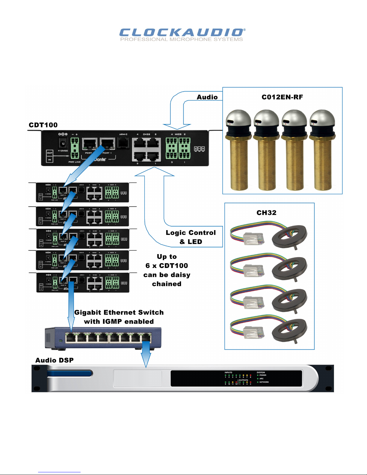
To daisy chain a device to another CDT100:
Connect an Ethernet cable from the data only port of the CDT 100 to one of the ports of the CDT100 to be chained to supply the network
informaon.
To chain the power, connect the “Link out” connector to the “Link in” connector on the CDT100 to be chained.
A third unit could be chained by connecng it in the same way to the second unit and so on.
CDT100 User Manual
© Clockaudio 2015
Figure 7 - Daisy Chain and Network Conguraon Example
5.1 – Dante Daisy Chaining - Example 1
Clockaudio Microphones - C012EN RF and Control Devices - CH32
12
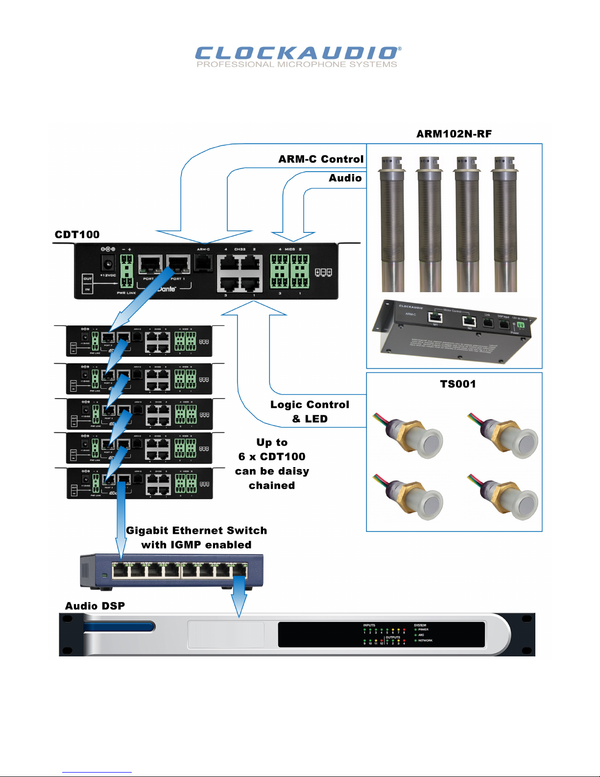
To daisy chain a device to another CDT100:
Connect an Ethernet cable from the data only port of the CDT100 to one of the ports of the CDT100 to be chained to supply the network
informaon.
To chain the power, connect the “Link out” connector to the “Link in” connector on the CDT100 to be chained.
A third unit could be chained by connecng it in the same way to the second unit and so on.
CDT100 User Manual
© Clockaudio 2015
Figure 8 - Daisy Chain and Network Conguraon Example
5.2 – Dante Daisy Chaining - Example 2
Clockaudio Microphones - ARM102N RF and Control Devices - TS001
13
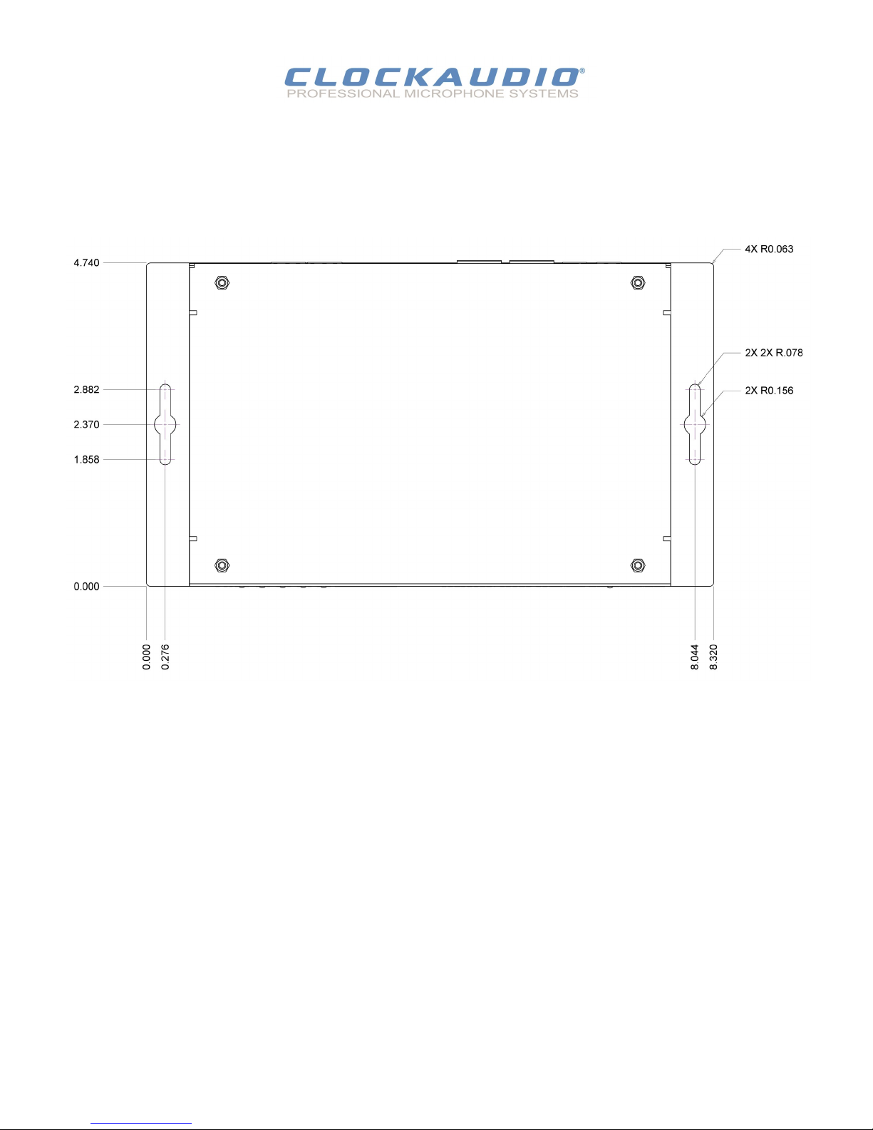
6 – Mounng
Installaon of the CDT 100 is very straight forward.
It is recommended that the unit be secured to a at surface with a screw through each mounng ange.
Dimensions for mounng are show in the Figure 9 below.
Use a No. 6 screw of a type and size that is applicable to the surface to which the CDT100 will be aached.
All connecons to the CDT 100 should be made before the power is applied.
Aach any audio sources that will be used to the inputs. The inputs are balanced so be sure to check what output type the
source to be connected uses in order to nd how to connect it correctly . (see Hardware Connecons secon).
When powering, using an oponal external supply:
Aach either Dante I/F port to a spare port on the Dante network switch using a CAT 5 cable.
Aach the power supply to the power input jack and then power up the external supply.
If all steps are performed correctly, the power light on the front should be lit. There may also be some acvity on the CDT 100
Dante I/F LED indicators.
With no Dante network, both LEDs will remain o.
If an acve connecon is made, both LEDs will come on and if there is network acvity, the yellow LED will ash.
Figure 9 - Mounng Informaon
CDT100 User Manual
© Clockaudio 2015
14
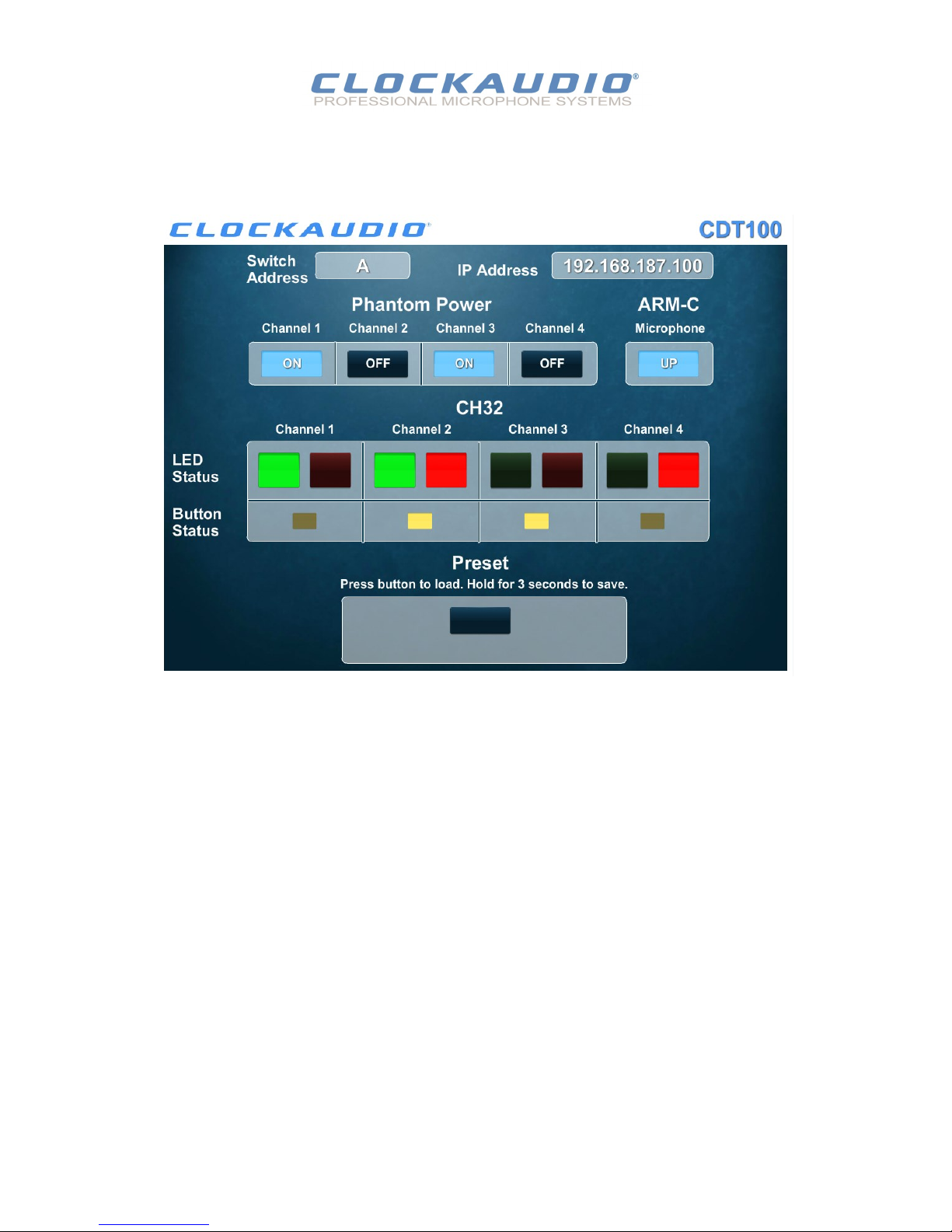
7 - Control Modules
1. Switch Address
2. IP Address
3. Phantom Power On/OFF
4. ARM-C Up/Down
5. LED Status
6. Buon Status
7. Preset buon
The CDT 100 supports controls from third party control systems.
AMX and Crestron control modules have been developed, tested and are available for free download at the Clockaudio website
(www.clockaudio.com) CDT100 product Technical Downloads.
Remote control capabilies of the CDT100 include the following control funcons:
Figure 10 - Demo Panel Window
CDT100 User Manual
© Clockaudio 2015

15
7.1 – Crestron
Simple Windows Name: Clock_Audio_CDT100_Module
Summary:
This module provides control and feedback of the Clockaudio CDT100 via UDP. It also provides true feedback.
General Notes:
Pulse the Inialize input before performing any other operaons.
The module ulizes a “Heartbeat” to maintain communicaon with the CDT100. This heartbeat will begin once preliminary
inializaon is complete.
Should a heartbeat response not be received, the module will aempt to send the heartbeat two more mes in succession.
If neither of these responses are received, the module will consider communicaon with the CDT100 to be broken, it will clear
all exisng data and output signals, and will aempt to re-establish communicaon with the CDT100 every 10 seconds.
Once communicaon has been re-established, the module will automacally re-inialize.
The module will automacally subscribe for available unsolicited feedback with the CDT100 upon inializaon.
Crestron Hardware Required: 3 Series Compable only
Setup of Crestron Hardware:
Connect Crestron 3-series processor via Ethernet port of same network that CDT100 is on.
Congure IP address of both Crestron and CDT100. (Ensure subnet sengs match).
Vendor Firmware: 99.5
OPS Used for Tesng: RMC3 (1.010.0060)
Sample Program: Clock_Audio_CDT100_Demo
Download the Crestron interface module and applicaon notes from the CDT100 product / Technical Downloads secon of the
website www.clockaudio.com.
© Clockaudio 2015
CDT100 User Manual

16
7.2 – AMX
To interface to the AMX Clock Audio CDT100 module, the programmer must perform the following steps:
Dene the device ID for the CDT100 that will be controlled.
Dene the NetLinx virtual device ID that the CDT100 COMM module will use to communicate with the main program and User
Interface.
If a touch panel interface is desired, demo programs have been created for tesng.
Touch Panel le - Clock Audio-CDT100_Demo_Panel.tp4
Demo program (ClockAudio_CDT100_Demo.axs
(Go to www.clockaudio.com CDT100 Technical Downloads).
The CDT100 module must be included in the program with a DEFINE_MODULE command. This command starts execuon of the
module and passes in the following key informaon: the device ID of the CDT100, and the virtual device ID for communicang to
the main program.
Issue the following SEND_COMMAND’s to the virtual device in the virtual device ONLINE event:
PROPERTY-IP_ADDRESS,<IP Address of the CDT100>
PROPERTY_IP_PORT,<UDP Port used to communicate with the CDT100>
REINIT
An example of how to do this is shown below.
DEFINE_DEVICE
dvCDT100 = 0:3:0
vdvCDT100 = 33001:1:0
dvTP_CH32_In = 10003:1:0
dvTP_CH32_Out = 10003:2:0
dvTP Arm_C = 10003:3:0
dvTP_Phantom = 10003:4:0
dvTP_Preset = 10003:5:0
DEFINE_MODULE 'ClockAudio_CDT100_Module' ClockAudioCDT100 (vdvCDT100, dvCDT100)
DATA_EVENT [vdvCDT100]
ONLINE:
SEND_COMMAND vdvCDT100,"PROPERTY-IP_ADDRESS,192.168.187.219"
SEND_COMMAND vdvCDT100,"PROPERTY-IP_PORT,49494"
SEND_COMMAND vdvCDT100,"REINIT"
Upon re-inializaon the AMX Comm module will communicate with the CDT100 and informaon will be exchanged.
Port Mapping
This module uses mulple virtual device ports in order disnguish events for one channel on the CDT100 from another
(i.e. virtual device port 1 = Channel 1, virtual device port 2 = Channel 2, etc.)
Virtual Device Buon Events Channels Levels Control Feedback
33001:1:0 – 33001:4:0 11, 2, 3, 4, 5, 6, 251, 252 None See tables See tables
CDT100 User Manual
© Clockaudio 2015
Download the AMX interface module and applicaon notes from the CDT100 product / Technical Downloads secon of the
website www.clockaudio.com.

17
© Clockaudio 2015
8 – Consultants Specicaons
The Dante interface unit shall provide four mic analog inputs on the rear panel via 3-pin de-pluggable connectors.
Each of the four inputs will have unity gain and a +48V phantom power opon shall be provided via soware for each input.
The unit shall provide two RJ-45 network connectors to allow Dante Daisy Chaining (DDC) of mulple units.
The internal analog to digital signal conversion shall be performed at 24-bit resoluon with a sampling frequency of 48kHz.
The Dante interface unit shall receive power from an external +12V supply.
Four control ports will be available for interfacing with switch buons and dual color LED.
An interface for motorized microphones shall be included.
The Dante interface unit shall be compable with third party control systems for exible control and monitoring in system
applicaons.
The Dante interface shall be compable with Clockaudio CH32 and other Clockaudio control devices.
The Dante interface shall be compliant with the RoHS direcve.
The Dante interface unit shall be compliant with the EMI/EMC requirements for FCC and CE.
The Dante interface unit shall be the Clockaudio CDT100.
Audio Inputs
Input Type: Balanced and RF ltered
Gain: 0dB
Input Impedance: >1.8K ohms at any gain
Phantom Power: +48V, soware selectable
Audio Performance:
EIN: -115dBu
System THD+N: <0.01% at any gain, input signal 3dB
below maximum
Frequency Response 20Hz – 20kHz, +/- 1dB
CH32 Control Device Inputs
RJ-45 Buon and Dual color LED
ARM Interface
RJ-12
Dante Network
Physical Level: Standard Ethernet
Connector: RJ-45
Cable Quality: CAT 5, CAT 6
Transmission Speed: 100 Mbps
Power Requirements +12V DC
Power Consumpon 4.9W Max
Dimensions 8.32” W x 1.50” H x 4.74” D
Weight 1.75 lbs
Compliance FCC CFR 47 Parts 15B ICES-003
CE (EN55022) RoHS
CDT100 User Manual
Other manuals for CDT100
1
Table of contents


