Clockaudio CCRM 4000 User manual

Installation and User Guide
CCRM 4000
(Motorised, Ceiling Retractable Microphone)


V2.1 2021-01 Page i of iv
Thank you for purchasing a Clockaudio product. We are confident that this product will give
you many years of trouble free operation.
As part of Clockaudio’s continual ongoing programme of product development,
improvements to the existing CCRM 4000 microphone range may be made to further
increase the already excellent reliability and functionality. As such specifications /
improvements are subject to change without prior notice.
This guide (latest version available from www.clockaudio.com) covers Installation and User
information.
From this version of the documentation, Clockaudio is removing the terms “Master” and
“Slave” and replacing them with “Main” and “Secondary” respectively.
Copyright
© Copyright 2020 Clockaudio Ltd. All rights reserved.
Disclaimer
This User Guide is written for users of the Motorised, Ceiling Retractable Microphone, to
assist in installation and operation. It is not intended to be a detailed source of information.
No part of this document may be reproduced in any form without the written permission of
the copyright owner.
The contents of this document are subject to revision without notice due to continued
progress in methodology, design and manufacturing. Clockaudio shall have no liability for
any error or damage of any kind resulting from the use of this document.

Page ii of iv V2.1 2021-01
READ ME FIRST – SAFETY INSTRUCTIONS
Please ensure that the following safety instructions are followed. If the product is reissued to another
party, please ensure that this document is provided.
1. Ensure that all warnings and important notes are adhered to;
2. Read and follow these instructions carefully as they contain important information concerning
safety and safe operation of this equipment;
3. Heed all warnings in this manual they are there for the safety of you and others;
4. Do not install the product near heat sources such as radiators, stoves, etc…;
5. Only use the attachments supplied, specified or recommended by Clockaudio;
6. Keep these instructions in a safe place in case they need to be referred to later;
7. If the unit needs to be cleaned, only use dry cloth; the unit is not waterproof;
8. There may be a risk of fire if the unit is exposed to dripping or running water or other liquids;
9. Do not burn or incinerate the remote control battery. Danger of explosion.
Warning!
Do not remove the covers as there is sensitive equipment inside. Only Clockaudio Ltd or its approved
service engineers are permitted to service this equipment. There are no user serviceable parts inside.
Caution!
Unauthorised maintenance, repair or the use of non-approved replacements may affect the
equipment specification and invalidate any warranties.
Equipment covered by this User Guide.
This User Guide covers all versions of CCRM 4000 product set. The product is specifically designed for
use in AV conference rooms, board rooms, court rooms, and huddle room applications or meeting
room spaces.

V2.1 2021-01 Page iii of iv
Contents
1 Overview ......................................................................................................................................... 1
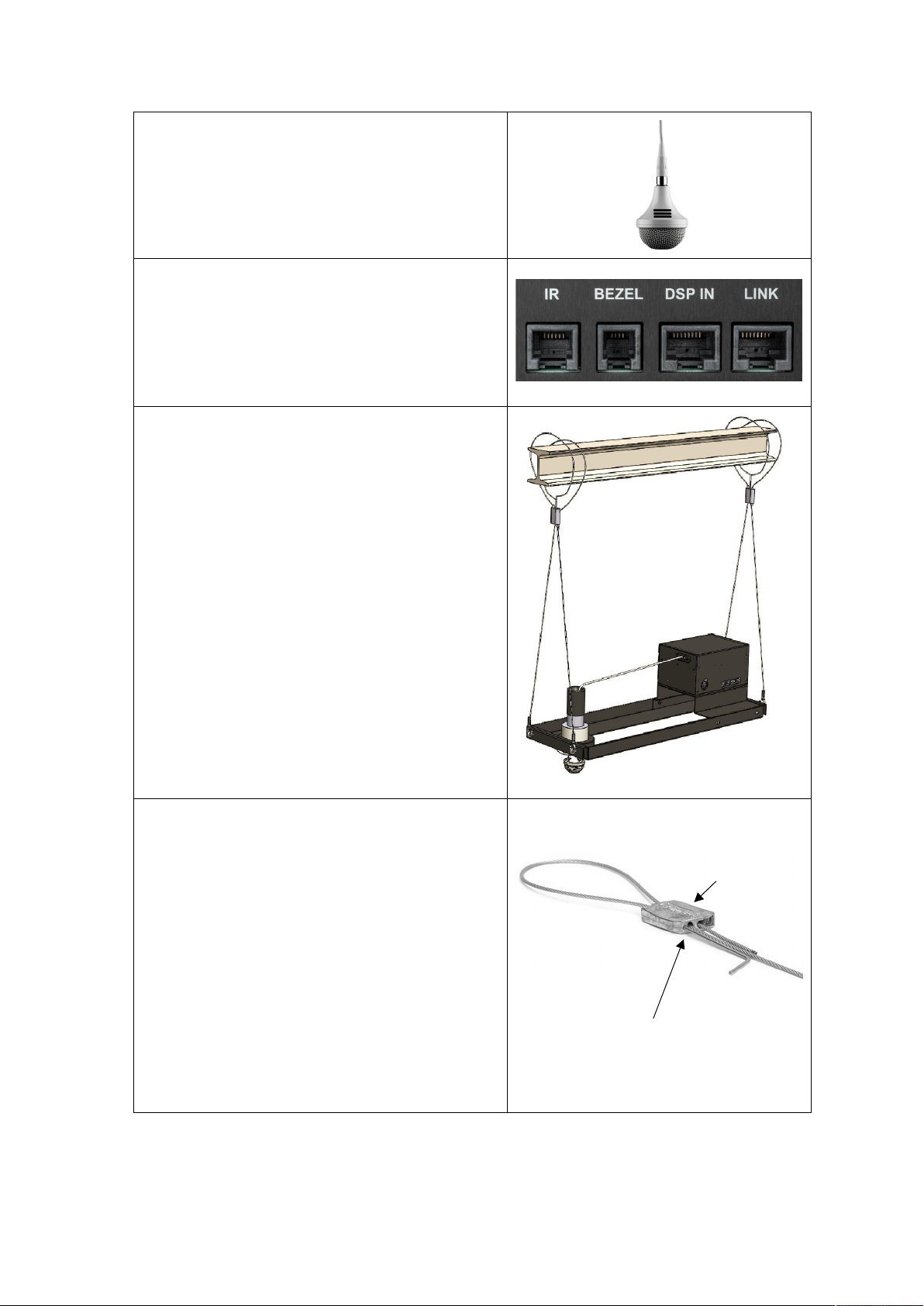
2 Package Contents ............................................................................................................................ 3
3 Installation ...................................................................................................................................... 4
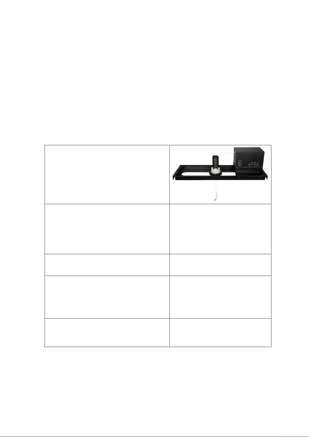
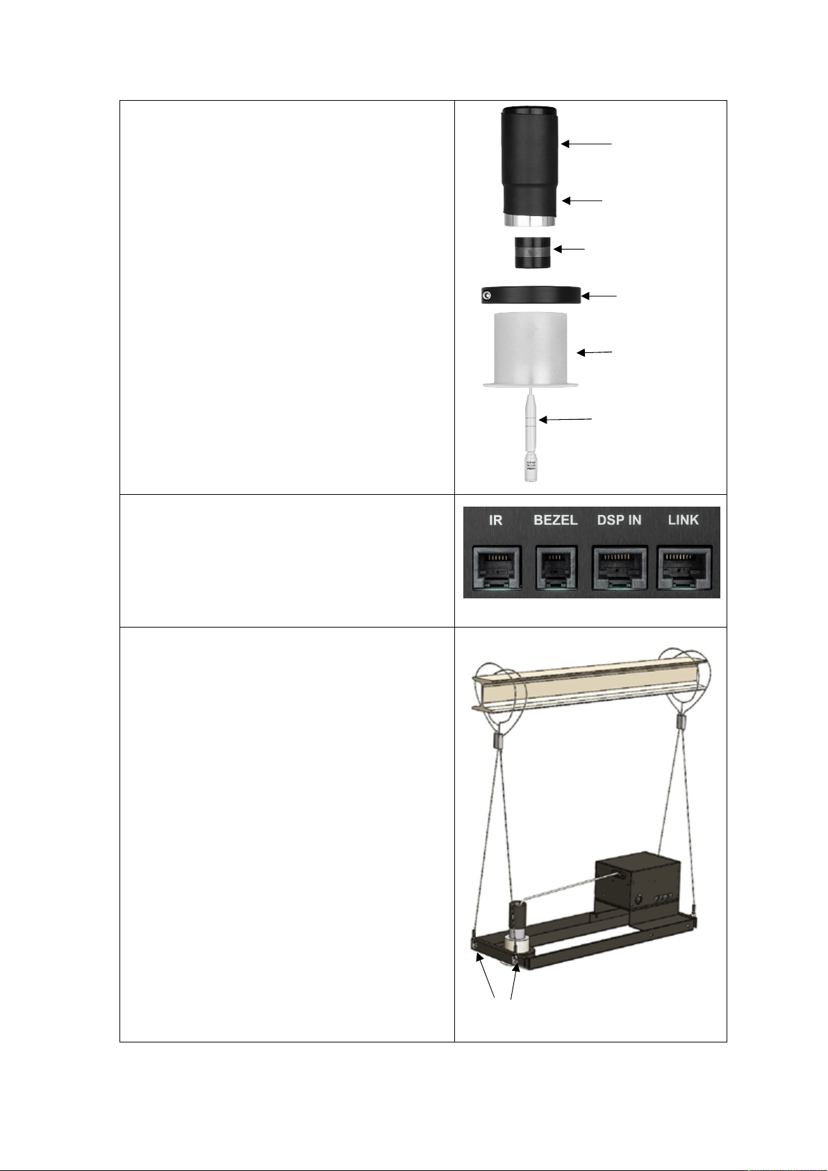
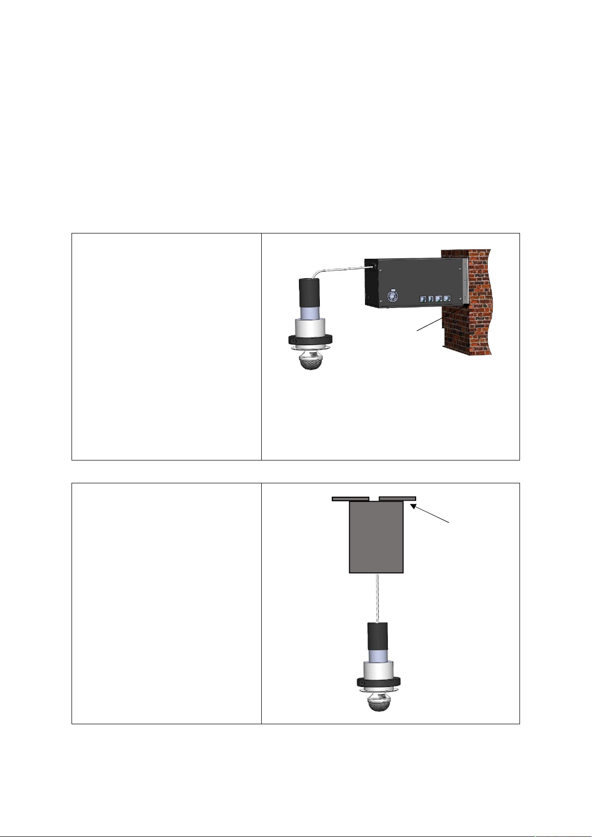
3.1 Single Element version of CCRM 4000 .................................................................................... 4
3.2 Tri Element version of CCRM 4000 ......................................................................................... 8
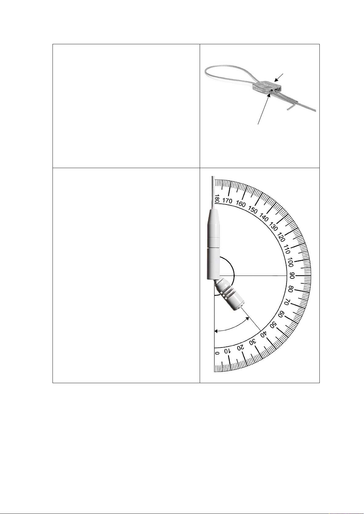
3.3 IR Sensor Installation ............................................................................................................ 11
3.4 Secondary unit wiring connections ....................................................................................... 11
3.5 Further Secondary wiring connection ................................................................................... 12
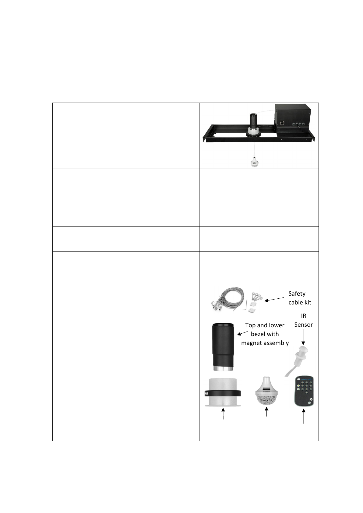
3.6 Horizontal / Vertical mounting ............................................................................................. 13
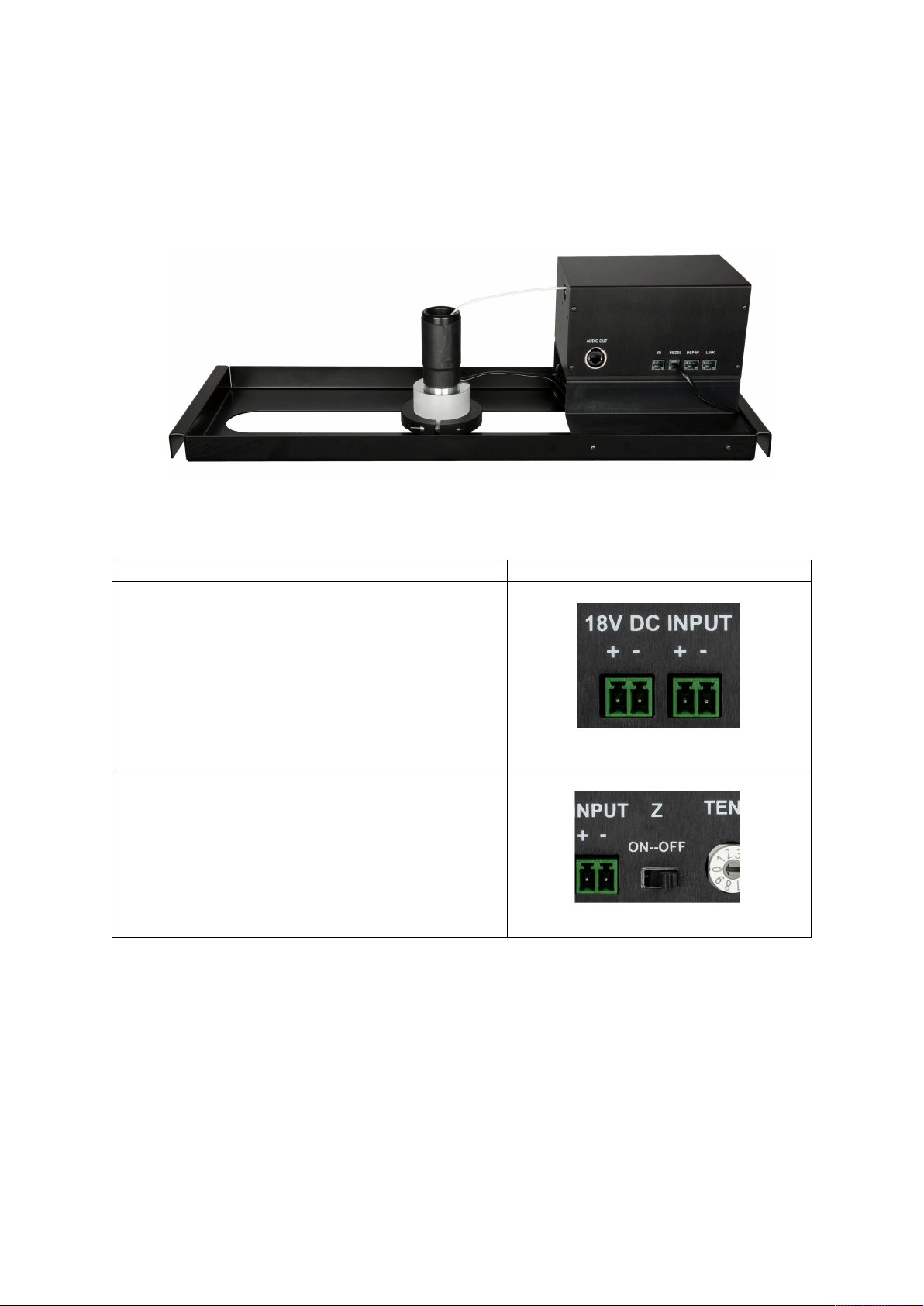
4 Controls and Connectors .............................................................................................................. 14
5 Connecting to DSP ......................................................................................................................... 16
5.1 CCRM 4000 DSP IN Connector .............................................................................................. 16
5.2 Main Unit Cable Wiring Connections using a DSP ................................................................ 16
5.3 DSP Mute Control ................................................................................................................. 17
5.4 Audio Out Socket .................................................................................................................. 18
5.4.1 Single Element version .................................................................................................. 18
5.4.2 Tri Element version ....................................................................................................... 18
6 Programming CCRM Cable Height ................................................................................................ 19
6.1 IR Remote Control Operation ............................................................................................... 19
6.2 IR Remote Layout .................................................................................................................. 19
6.3 IR Remote Control Additional Information ........................................................................... 20
6.4 Programming Cable Height on Main Unit ............................................................................. 20
6.5 Programming Cable Height on Secondary Unit .................................................................... 21
6.6 Programming Multiple Units ................................................................................................. 21
6.7 Microphone Deployment Safety Feature ............................................................................. 21
7 Troubleshooting ............................................................................................................................ 22
8 Specifications ................................................................................................................................ 23
9 Product Warranty ......................................................................................................................... 24
10 Product Disposal ........................................................................................................................... 25

Page iv of iv V2.1 2021-01

V2.1 2021-01 Page 1 of 25
1 Overview
The CCRM 4000 product is designed for use in AV conference rooms, board rooms, court rooms, and
huddle room applications or meeting room spaces. Typically mounted in the ceiling space, it allows
the microphone to be released smoothly from the unit and drop down to a predefined height and
when not in use to smoothly retract back into the ceiling.
Designed by Clockaudio, the CCRM 4000 fulfils its goal of a reliable motorised retractable
microphone that frees up the desk space.
Major Features of CCRM 4000 includes:
Cardioid microphones that provide an excellent front to back rejection.
Automatic safety detection for cable hang-ups.
Logic Hi / Lo for DSP mute detection port.
Ceiling bezel fitted with a detection switch that allows the microphone to establish the
home position.
Single element cardioid microphone allows a 350 degree rotation of the element with 40
degree knuckle joint angle.
Tri element cardioid microphone allows pickup of 360 degrees.
Automatic microphone deployment via an external positive (+2.5V to +12V) signal applied to
the Main’s DSP port or via the IR sensor. Triggering the Main unit will also deploy any other
attached Secondary units.
Microphone output provided via a XLR socket or an RJ45 connector. If microphone was a
single element version, then output will be via an XLR connector. If it was tri element then
output would be an RJ45.
Easy and fast connection of the audio from CCRM 4000 to mixer or DSP. A 9-48 Volt
phantom power is required.
Expansion capability to link/daisy chain other CCRM 4000 units. Up to 99 Secondary units
can be daisy chained to a single Main unit.
Main and Secondary units are identical in construction. Two rotary 0-9 digital decimal
encoders define and set unit’s address ID as well what it becomes – “00” for Main unit and
“01-99” for Secondary units.
IR remote control is supplied with the Main unit. Remote control can be used to activate the
unit(s) in the absence of a DSP.
IR receiver sensor with integral green programme mode LED and red range LED (supplied
with Main unit).
Universal mains switched mode power supply available as separate item. Operates up to 4
units.
Audio cable length 2.5 Metres (8.2 feet).

Page 2 of 25 V2.1 2021-01
The CCRM 4000 is available with either a single element (C3) or a tri element (C303) microphone.
Both microphones, available in either black or white finish, provide an excellent pickup and proven
audio quality.
Definition of whether the product appears as a Main or Secondary device is defined by the settings
on the two rotary decimal encoders. If the address ID is set to 00, the unit is Main else Secondary.
It is important to note that the only difference between the Main unit and Secondary unit is that
with the Main unit, the IR receiver sensor, IR remote control and the PSU are supplied. With
Secondary units, these three items are not supplied.
The single element cardioid microphone is mounted on a knuckle joint that allows 350 degree rotation
with up to 40 degrees bend.
The tri element capsule cardioid microphone has capsules positioned at 120 degrees apart providing
a full 360 degree pickup.
For North American market, the CCRM 4000 is available with a Plenum enclosure for both the single
element and tri element microphones.
Ordering options available for the CCRM 4000 are:
Type
Finish
Single Element
Tri Element
Main
Black
CCRM 4000-M-RF
CCRM 4000-M-C303-RF
White
CCRM 4000W-M-RF
CCRM 4000-M-C303W-RF
Secondary
Black
CCRM 4000-SL-RF
CCRM 4000-SL-C303-RF
White
CCRM 4000W-SL-RF
CCRM 4000-SL-C303W-RF
Plenum
(Main)
White
CCRM 4000W-M-RF-P
CCRM 4000-M-P-C303W-RF
Plenum
(Secondary)
White
CCRM 4000W-SL-RF-P
CCRM 4000-SL-P-C303W-RF
Options:
Part Number
Description
CCRM 4000-MB
Wall mounting brackets (supplied as a pair)
CCRM4000B
Wall mounting brackets for CCRM4000 – North America only
PSU-018
Power supply 18VDC 2A (Supplied with Main unit)
CCRM PSU-018
Power supply 18VDC 2A (Supplied with Main unit) – North America only
CCRM 4000-R
Remote Control for CCRM 4000
CCRM 4000-IR
Infrared sensor for CCRM 4000

V2.1 2021-01 Page 3 of 25
2 Package Contents
The following part are supplied with each of the product types
CCRM 4000 Type
Main, Single Element
Secondary, Single Element
Main, Tri Element
Secondary, Tri Element
Main, Plenum, Single Element
Secondary, Plenum, Single Element
Main, Plenum, Tri Element
Secondary, Plenum, Tri Element
CCRM 4000 unit
Single element microphone
Tri element microphone
Audio link cable
IR receiver sensor (CCRM-4000-IR)
IR remote control (CCRM-4000-R)
+18 VDC universal power supply
Safety 4 x eye bolts and wire harness
Ceiling tile fixing bracket (CCRM-4000-Rack)
Ceiling Bezel (black or white, colour
dependent upon order)
Installation and User Guide
Plenum enclosure

Page 4 of 25 V2.1 2021-01
3 Installation
This section describes the installation steps required for Single and Tri Element variants.
See Section 5.4 on connecting the audio cable to the DSP.
3.1 Single Element version of CCRM 4000
To prevent unnecessary damage to the system it’s vitally important to follow the instructions
below:
1.
The CCRM 4000 is supplied partially
disassembled and requires simple push to fit
reassembly. The adjacent image shows a fully
assembled unit.
2.
Remove the CCRM 4000 system from its
transportation box and remove the 2 foam end
caps. The transportation box and packing
should be stored as this is the best packaging
to use in the unlikely event of having to return
the system to your dealer.
3.
Cut the tape securing the large cardboard box
to the large black ceiling frame.
4.
Carefully move the box out of the ceiling frame
and set to one side being careful not to snag or
cause the microphone cable to kink. Do not
remove the microphone and top bezel
assembly at this stage.
5.
Remove the small cardboard box located under
the CCRM 4000. This contains the PSU (Main
unit only).

V2.1 2021-01 Page 5 of 25
6.
Now open the large cardboard box and remove
from the packaging the microphone and large
ceiling bezel with bezel clamp.
7.
To install this system, cut a 65 mm (2.56") hole
into the ceiling tile to allow the large ceiling
bezel, just removed from the packaging, to be
fixed to the tile. The hole should ideally be cut
in the centre of the tile and must not be closer
than 76mm (3") from the edge of the tile or it
will not be possible to align the CCRM 4000
support bracket over the hole.
8.
Take the entire CCRM 4000 kit up to the final
location site. Carefully align the CCRM 4000
complete with ceiling tile bracket so that the
large slot is directly over the hole that has
previously been cut in the ceiling for the bezel.
Ensure that the front and back of the bracket
fits snugly over the ceiling tile “T-Bar rails”.
Secure the ceiling bracket to the T Bar rails
using the supplied four eye bolts finger tight.
9.
Insert the ceiling bezel up through the ceiling
tile through the hole and slot in the tile
bracket. Secure the bezel in place with the
bezel clamp using a 5mm Allen key.
10.
Now carefully remove from the foam packing
the IR sensor, remote control and safety cable
fixing kits and set aside.
Next remove the top bezel containing the
magnet assembly and Mini XLR microphone
connector.
Eye
bolts
65mm
(2.56”)
hole
Ceiling bezel
with clamp
IR
Sensor
Microphone
Safety
cable kit
Top and lower
bezel with
magnet assembly
Remote

Page 6 of 25 V2.1 2021-01
11.
Insert the microphone through the lower
ceiling bezel and then push fit the top part of
the bezel to the lower bezel making sure the
magnet is inside the top part of the bezel.
12.
Remove any kinks or bends in the cable by
gripping the cable with your hands and pass it
through a clean dry cloth a few times. This will
straighten the cable. Connect the RJ12 plug
from the top bezel into Socket 2 (BEZEL) on the
Main unit.
13.
For safety reasons the frame to ceiling tile
fixing eye bolt (2 at each end of the bracket)
are used to secure the frame and also used to
suspend the CCRM 4000 and bracket. Unravel
the Y cable harnesses and attach the hooks to
the eye bolts at each end of the ceiling tile
bracket.
Top bezel
Lower bezel
Magnet assembly
Single element
microphone
Ceiling bezel
Eye bolts (2 at each end)
Bezel clamp

V2.1 2021-01 Page 7 of 25
14.
Push the free end of the cable harness through
one of the holes located on the Gripper. Now
loop the free end of the cable over a secure
fixing such as a ceiling truss, eye bolt, or any
structure capable of taking 7Kgs of weight.
Now pass the cable through the remaining hole
in the Gripper and then pull on the cable to
adjust / take up the slack. Do the same with
the other Y cable at the other end of the ceiling
tile bracket.
Cable can be slackened or removed by
inserting the supplied release key into the hole
as shown.
15.
Knuckle Joint adjustment:
After installation has been completed it is
important to operate the unit a few times to
allow the cable to settle and find its natural
final rest position. The microphone can then be
aligned correctly and the knuckle joint angle
positioned for best audio reception.
Important: The microphone angle is limited to
40 degrees from vertical as shown.
NOTE: If the cable hits an obstruction such as a
desk / floor or is held preventing the upward
motion (0.5lbs pull) of the cable motor will
immediately stop. Remove the obstruction and
then press the up button on the remote, or up
command if using a DSP. The unit can now be
operated normally. Should this fail to restore
normal operation disconnect and reconnect
the supply Voltage to the CCRM 4000.
Insert release key
into hole
Gripper

Page 8 of 25 V2.1 2021-01
3.2 Tri Element version of CCRM 4000
To prevent unnecessary damage to the system it’s vitally important to follow the instructions
below:
1.
The CCRM 4000 is supplied partially
disassembled and requires simple push to fit
reassembly. The adjacent image shows a fully
assembled unit.
2.
Remove the CCRM 4000 system from its
transportation box and remove the 2 foam end
caps. The transportation box and packing
should be stored as this is the best packaging
to use in the unlikely event of having to return
the system to your dealer.
3.
Cut the tape securing the large cardboard box
to the large black ceiling frame.
4.
Remove the small cardboard box located under
the CCRM 4000. This contains the PSU (Main
unit only).
5.
Now open the large cardboard box and remove
from the packaging the microphone and large
ceiling bezel with bezel clamp.
Ceiling bezel
with clamp
IR
Sensor
Microphone
Safety
cable kit
Top and lower
bezel with
magnet assembly
Remote

V2.1 2021-01 Page 9 of 25
6.
To install this system, cut a 65 mm (2.56") hole
into the ceiling tile to allow the large ceiling
bezel, just removed from the packaging, to be
fixed to the tile. The hole should ideally be cut
in the centre of the tile and must not be closer
than 76mm (3") from the edge of the tile or it
will not be possible to align the CCRM 4000
support bracket over the hole.
7.
Take the entire CCRM 4000 kit up to the final
location site. Carefully align the CCRM 4000
complete with ceiling tile bracket so that the
large slot is directly over the hole that has
previously been cut in the ceiling for the bezel.
Ensure that the front and back of the bracket
fits snugly over the ceiling tile “T-Bar rails”.
Secure the ceiling bracket to the T Bar rails
using the supplied four eye bolts finger tight.
8.
Insert the ceiling bezel up through the ceiling
tile through the hole and slot in the tile
bracket. Secure the bezel in place with the
bezel clamp using a 5mm Allen key.
9.
Now carefully remove from the foam packing
the IR sensor, remote control and safety cable
fixing kits and set aside.
Next remove the top bezel containing the
magnet assembly and Mini XLR microphone
connector.
10.
Carefully feed the Mini XLR microphone
connector through the lower bezel and push fit
the top part of the bezel over the lower bezel,
making sure the magnet assembly is inside the
top part of the bezel.
Eye
bolts
65mm
(2.56”)
hole
Top bezel
Lower bezel
Magnet assembly
Tri element
microphone
Ceiling bezel
Bezel clamp
Mini XLR

Page 10 of 25 V2.1 2021-01
11.
Connect the microphone on to the Mini XLR
connector (push fit).
WARNING: Do not operate the CCRM 4000
without connecting the microphone.
12.
Remove any kinks or bends in the cable by
gripping the cable with your hands and pass it
through a clean dry cloth a few times. This will
straighten the cable. Connect the RJ12 plug
from the top bezel into Socket 2 (BEZEL) on the
Main unit.
13.
For safety reasons the frame to ceiling tile
fixing eye bolt (2 at each end of the bracket)
are used to secure the frame and also used to
suspend the CCRM 4000 and bracket. Unravel
the Y cable harnesses and attach the hooks to
the eye bolts at each end of the ceiling tile
bracket.
14.
Push the free end of the cable harness through
one of the holes located on the Gripper. Now
loop the free end of the cable over a secure
fixing such as a ceiling truss, eye bolt, or any
structure capable of taking 7Kgs of weight.
Now pass the cable through the remaining hole
in the Gripper and then pull on the cable to
adjust / take up the slack. Do the same with
the other Y cable at the other end of the ceiling
tile bracket.
Cable can be slackened or removed by
inserting the supplied release key into the hole
as shown.
Insert release key
into hole
Gripper

V2.1 2021-01 Page 11 of 25
3.3 IR Sensor Installation
Mount the IR sensor in a position (ceiling or wall) where it will be convenient to
see all the CCRM 4000 movements whilst maintaining good line of site with the
IR sensor. Do not place any obstruction in front of the sensor as this will prevent
operation.
Drill a 16mm (5/8") diameter hole. Pass the sensor through the hole and secure it using the C clip.
Connect the cable to the IR sensor input Socket 1 (IR) on the CCRM 4000 unit.
IR sensor has 2 coloured LED’s: Green illumination while in programme mode and Red during normal
operation. The LEDs will illuminate each time a button is pressed on the remote.
3.4 Secondary unit wiring connections
When adding a second CCRM 4000 unit as a Secondary device
1.
Connect a DC supply cable between the
Main and Secondary DC input sockets.
Make sure that the correct polarity is
applied to the Phoenix plug supplied.
Use a minimum AWG 18 wire gauge to
connect DC power between CCRM 4000
units. Try and keep the cable as short as
possible.
2.
Make sure that the “Units” rotary decimal
encoder is set to other than “0” e.g. “1”
(01).
3.
Connect Socket 4 (LINK) on the Main unit to
Socket 3 (DSP IN) on the Secondary unit
using an RJ45 straight through cable.
4.
Connect the Bezel cable to Socket 2 (BEZEL)
5.
Connect the appropriate cable to the DSP –
XLR for the single element and CAT5 cable
for the tri element.
Positive (+)
Negative (–)

Page 12 of 25 V2.1 2021-01
Important: When using a DSP to control the system ensure that the DSP control signal is already
outputting +V to Socket 3 (DSP IN) on the CCRM 4000 Main unit (+2.5 to 12 Volts) before powering
the system up. Otherwise the DSP command will not be recognised by the system and unit will fail
to operate.
3.5 Further Secondary wiring connection
For addition of further Secondary units, connect a CAT5 between Socket 4 (LINK) and Socket 3 (DSP
IN) of the next Secondary. Repeat for additional units to form a daisy chain. Ensure that each
additional CCRM 4000 unit is set with a unique address using the rotary decimal encoder e.g. “2” for
second, “3” for third, etc…
Up to 99 Secondary units can be linked together in the same / identical way.
Main / Secondary CCRM 4000 Connectivity Diagram
IR
Sensor
Bezel
DSP
Bezel
Main
unit
Secondary
unit
To next
Secondary
CCRM 4000

V2.1 2021-01 Page 13 of 25
3.6 Horizontal / Vertical mounting
Apart from mounting the CCRM 4000 units in the ceiling space, these units can also be mounted on a
wall or a bracket attached to the ceiling. In either case a secure bezel attachment, where the
microphone emanates from, will need to be addressed by the installer.
Caution: When mounting horizontally on a wall or vertically on a ceiling or a support, ensure that
the correct type of fasteners are used to support the CCRM 4000. As each type of install is
different, fasteners are not supplied.
Horizontal mounting:
Using a pair of metal brackets (fixed
using 6 x M4 x 12 countersunk screws),
attach the CCRM 4000 to the wall.
Mount the bezel appropriately where
required.
Remember that the further away the
unit is mounted from the microphone
and bezel, less cable will be available for
the cable drop (cable length is 2.5
Metres max (8ft 2in.)).
Wall fixing metal brackets are available
as optional extra.
Vertical mounting:
Using a pair of metal brackets (fixed
using 6 x M4 x 12 countersunk screws),
attach the CCRM 4000 to the ceiling.
Mount the bezel appropriately where
required.
Remember that the further away the
unit is mounted from the microphone
and bezel, less cable will be available for
the cable drop (cable length is 2.5
Metres max (8ft 2in.)).
Wall fixing brackets are available as an
optional extra.
Metal Brackets
Metal Brackets

Page 14 of 25 V2.1 2021-01
4 Controls and Connectors
On both sides of the CCRM 4000 there are controls and connectors.
Description
Connector
Power
Two +18VDC power connectors are provided. One can
be used for power In, while the other can be used to
distribute power to the next daisy chained unit.
Using Clockaudio recommended PSU, up to 4 CCRM
4000s can be daisy-chained.
Impedance matching “Z”
On each of the units is a slide switch “Z”. In a
multi-unit system of 2 or more units, it is only the final
Secondary unit that needs to have this switch ON and
all other units’ switches must be OFF.
This manual suits for next models
12
Table of contents
Other Clockaudio Microphone manuals

Clockaudio
Clockaudio CRM 202-RF User manual

Clockaudio
Clockaudio SM 80-RF User manual

Clockaudio
Clockaudio CCRM4000-C303 Guide

Clockaudio
Clockaudio ARM 102-C MK2 User manual

Clockaudio
Clockaudio CUB-33 User manual

Clockaudio
Clockaudio CCRM 4000-Retracta Guide

Clockaudio
Clockaudio CRM 203 RF User manual

Clockaudio
Clockaudio C 303-RF User manual

Clockaudio
Clockaudio TIM-1000 User manual