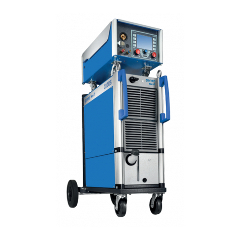
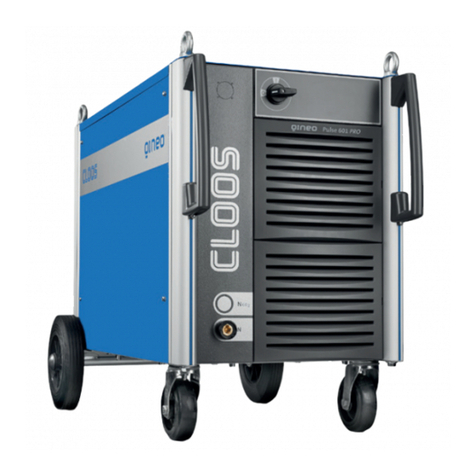
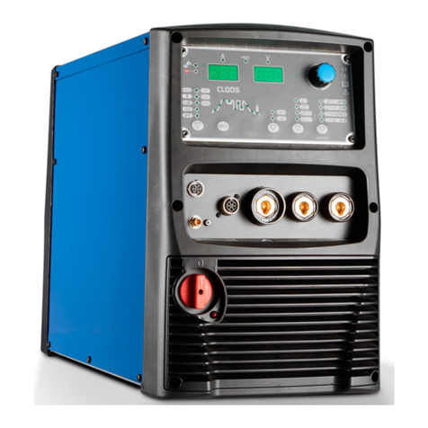
Cloos GLC 353 MC3 User manual

16
GLC 353/503/553 MC3Operatinginstructions
GLC 353 MC3
GLC 503 MC3
GLC 553 MC3
MIG/MAG Welding Machine OPERATING INSTRUCTIONS
and SPARE PARTS LISTS
PLEASE KEEP SAFELY FOR FUTURE REFERENCE
128/01.01
CARL CLOOS
Schweißtechnik GmbH
Industriestr. • 35708 Haiger
Tel. +49 2773/85-0
Fax. +49 2773/85-275
http://www.cloos.de


1
GLC 353/503/553 MC3Operatinginstructions
Operating Instructions
MIG/MAG Welding Machine
GLC 353 MC3
GLC 503 MC3
and
GLC 553 MC3
with
CK 98 A Wire Drive Unit
Print No.: 128
Issued: 01/01
Subject to technical alterations

2
GLC 353/503/553 MC3Operating instructions
W A R N I N G !
Prior to the first commissioning, all persons who are involved with
this machine should read this operating instruction manual
carefully and confirm that they have done so in writing.
Please keep the operating instruction manual easily accessible for
all welders and service staff!
The best place is the welding machine itself!

3
GLC 353/503/553 MC3
Operating instructions
EN50199:1995
Appendix A (information)
Installation and use
Theuser is responsiblefor the installationand operation ofthe welding machineaccording to themanufacturer's
instructions. If there is electromagnetic interference, the user is responible for finding a solution with the aid of
the manufacturer of the welding machine, e.g. grounding of the weld current circuit, electromagnetic screening
and/or inlet filter.
A.1 Evaluation of the area
Before installing the welding machine, the user has to evaluate any possible electromagnetic problems in the
surrounding area. The following must be taken into consideration:
a) Other mains supply lines, control lines, signal and telecommunication lines above, below and next
to the welding machine.
b) Radio and TV broadcasting station and receiver.
c) Computer and other control units.
d) Safety devices, e.g. protection for commercial equipment.
e) Health of persons in vicinity, e.g. if using pacemakers and hearing aids.
f) Units for calibration or measement.
g) Resistance to interference of other equipment in the surrounding area. The user must ensure that
other equipment used in the vicinity is electromagnetically compatible. This may require additional
safety measures.
h) The time of day when welding or other activities are being carried out.
The extent of the surrounding area to be considered depends on the construction of the building and other
activities which take place there and may exceed the boundaries of the property.
A.2 Procedure to reduce emissions
A.2.1 Mains supply
The manufacturer recommends that the welding equipment is connected to the mains supply. Where there is
some interference, additional safety precautions may be necessary, i.e. filter for the power supply.
A.2.2 Maintenance of the welding equipment
Regular maintenance intervals are recommended by the manufacturer.
A.2.3 Weld cables
Welding cables should be as short as possible and should be run close together on or near to the floor.
A.2.4 Potential equalization
Theelectric connectionofall metalparts in andnear a weldingmachine should betaken intoaccount.The metal
parts connected to the workpiece may increase the risk of an electric shock if the welder touches these metal
parts and the electrode at the same time. The welder should be protected against all connected metal parts.
A.2.5 Earth connection of workpiece
It must be ensured that earthing of the workpiece does not increase the risk of accident to the user or causes
damage to other electrical equipment.
A.2.6 Screening
Selectivescreening of othercables and equipmentin thevicinity may reduceelectrical interference. Screening
of the complete welding equipment may be considered in special situations.
5/96

4
GLC 353/503/553 MC3Operating instructions

5
GLC 353/503/553 MC3
Operating instructions
Safety specifications..........................................................................................7-9
Particular information for welding ..............................................................................7
Technical data .............................................................................................9
General product description ................................................................................ 10
Operating instructions ...................................................................................10-13
Transport ...........................................................................................10
Mounting area, floor requirement, environment ..................................................... 10
Storage ...........................................................................................11
Assembly ...........................................................................................11
Power supply ...........................................................................................11
Torch connection, earth cable ...............................................................................11
Shielding gas, reducing valve................................................................................ 11
Wire drive ...........................................................................................12
Coolant ...........................................................................................12
Commissioning ...........................................................................................13
Special safety devices......................................................................................... 13
Temperature protection ......................................................................................... 13
Overload protection ...........................................................................................13
Operation / Service ...........................................................................................13
General instructions for shielded gas welding ............................................13-14
Instructions for welding...................................................................................... 15
Operation......................................................................................B-1-44
Mechanical description ............................................................................... L- 1-24
Illustrations welding machine GLC MC 3..............................................................2-5
Spare parts list GLC MC 3....................................................................................6-7
Illustrations wire drive unit CK 98 A......................................................................8-9
Spare parts list CK 98 A........................................................................................10
Sectional drawing: 2 + 2 roller system with central connection..............................11
Spare parts list 2+2 roller drive compl. with central connection
for steel and flux cored wire..............................................................................12-13
Sectional drawing: 2 + 2 roller system with central connection..............................14
Spare parts list aluminium equipment for 2+2 roller drive with central connection ..... 15
HD Drive ..........................................................................................................16
Spare parts list HD Drive ..................................................................................17-18
Sectional drawing cable assembly for CK 98 A .....................................................19
Spare parts list cable assembly CK 98 A............................................................... 20
Sectional drawing cable assembly for CK 98 A, cable assembly connectable ...... 21
Spare parts list cable assembly CK 98 A, cable assembly connectable................22
Sectional drawing wire coil holder compl............................................................... 23
Spare parts list for wire coil holder compl. .............................................................24
Electrical description ................................................................................ L- 25-53
Circuit diagrams GLC 353 MC 3.......................................................................25-27
Electrical parts list GLC 353 MC 3....................................................................28-33
Circuit diagrams GLC 553 MC 3.......................................................................34-36
Electrical parts list GLC 553 MC 3....................................................................37-40
Circuit diagram CK 98 A ........................................................................................ 41
Electrical parts list CK 98 A ..............................................................................42-43
Circuit diagram CK 98 A with installation kit remote controller socket ..............44-45
Electrical parts list CK 98 A .............................................................................46-47
Circuit diagram CK 98 A, cable assembly connectable ...................................48-49
Electrical parts list CK 98 A, cable assembly connectable ..............................50-51
Circuit diagram remote controller .......................................................................... 52
Electrical parts list remote controller...................................................................... 53
APPENDIX
Supplement cooling water device .......................................................................... 51
List of addresses - CLOOS representatives in Germany/abroad ..................... A1-A4
INDEX

6
GLC 353/503/553 MC3Operating instructions

7
GLC 353/503/553 MC3Operatinginstructions
Safety specifications
Generalinformation
Warning!
This is a class A equipment which may cause radio
interferences in residential areas. In such a case the
operator may be asked to take adequate steps on his
account.
TheGLC 353/503/553MC3 machine withCK 98A is
built according to EN 60 974-1. It corresponds to the
latest "state of the art" engineering and its reliability
isproven.Itmustbeoperatedbytrainedpersonnel in
accordancewiththefollowinginstructionstoprovide
safeandefficientoperation.
The machine is not suitable for thawing
pipelines due to Fire risk !
Flammable gases or gases which induce a chemical
reaction,such asAcetylene, Propane, pureHydro-
gen,pureOxygenareprohibited.
Pleasenotethefollowing!
-SafetyregulationsVBG15
-SafetyregulationsVBG4
-Fireprotectionrules
-Weldingandmaintenancetobecarriedout by
qualifiedpersonnelonly.
-Themachinemustbeswitched-offand
disconnectedforallmaintenancework.
-Repairofelectronicstobecarriedoutby service
personnelonly. Ifrepairwork iscarried outby
unauthorizedpersonsandsafetyregulationsare
notadheredto,thewarrantybecomesinvalid.
Thiswelding machineisintended forindustrialuse
and must not be used in residential buildings.
As >16 Amp are required per phase, this machine is
subjectto the IEC 61000-3-4 standardor EN61000-3-
12,when it isavailable.In ordertoavoid
electromagnetic interference (EMI), certain conditions
must exist (size of mains impedance) for connection
tothe publiclowvoltage network.Please informthe
relevant electricity supplier about this machine’s
connection. Please do not hesitate to contact your
Electricitysupplier or the manufacturer if you need
helpor information.
Particularinformationforwelding
Personalprotection(rays,gases,vapours)
—Whenwelding,dryprotectiveclothing,apron,
helmet and gloves as well as solid work shoes
shouldbeworn.
—Use a protective shield or helmet with glass, with
DINmarking,outsideclear,insidetinted.
—Protectother personsin thevicinity of the
weldingarea fromUV raysand spatter by
suitable,non-flammablepartitionwalls.
—Always wear safety glasses if you are in an area
whereweldingtakesplace.
—Wear safety glasses with side protection when
youareweldingorwhenremovingslag.
—Caution!UVraysarereleasedduringwelding.
Protect body and particularly the eyes. Keep
protectiveointmentandeyedropsavailable.
—Allmetalvapoursaretoxic!Becarefulwith
alloys whichcontainlead,cadmium,copper,
zinc,nickle,chrome,berillium.
—Parts, cleaned with chlorinated agents, cause the
toxic gas phosgen to form in the arc.
Caution Risk of poisoning in narrow places !
If shielding gas hoses are not tight or the
shieldinggas valvegetscaught unintentionally,
shielding gas may escape to such an extent that
the oxygen content of the inhaled air decreases;
symptoms of poisoning appear which may lead to
unconsciousnessand suffocation.Sufficient fresh
airmust be provided! Please check the gas
supplyingpartsat regular
intervals.
Fire prevention (explosion)
—Removeallflammablematerialsaroundthe
weldingplaceorcoverthesewithanon-
flammablematerial.
—Hot slag or spatter might cause fires if in contact
withflammablematerials.
—Onlyuse shielding gasessuitablefor welding,
such as Argon, CO2and Argon and CO2or
Argon,CO2andO2mixtures.
NeveruseflammablegaseslikeAcetylene,
Propane,Hydrogenorfiresupportinggasessuch
as Oxygen.
—Neverweldondrums,tanksorsimilarcontainers
unlesstheyhavebeenthoroughlycleanedand
youare surethat notoxic, flammableor explosi-
vevapourcandevelop.
—Fire fighting agents such as water or sand or a
fireextinguishershouldalwaysbeavailable.
—Confinedspacesmusthaveafreepassage
allowingescapeincaseof danger.
—Pleaseobservethe weld areaandits
surroundingswhenweldinghasfinished.Fire
maybreak outlater due tosmoldering.
Electrical danger (current, voltage)
Pacemakers
Wearers of pacemakers may potentially by at risk
fromarcwelding.When MIG/MAG weldingtheriskis
frommagneticfieldsandwhenTIGweldingfromhigh
voltagepulsesofthearcignition units.

8
GLC 353/503/553 MC3Operatinginstructions
Asthereareseveralversionsofpacemakers,the
situationmustbeclarifiedwiththerelevant
pacemakermanufacturersortheirrepresentatives
(hospitaletc.).
—Switchoff the weldingmachinewhen notinuse
topreventanyelectricalrisk.
Warning! The terminal voltage of the welding
machine may be up to 113V= or 48V~!
—If you have to stand on metal or in a wet area
duringwelding,insulationwithsuitabledry
materialsisrequired.
—Avoidcontactwithwetorconductivemetalparts;
weardryclothing.
—Alwaysmaintaincorrect insulationofcables,
plugsandweldingtorches.Donotoverload
these parts.
—Keepeverythingdry,includingclothing,welding
area,cablesandweldingmachine.Repair
immediatelyanyfaultywatercoolinglines.
—Weldingmachinesmayonly be usedifallcovers
arepresentandcorrectly installed.
—Althoughthemachineismarked“S”(approved
forweldinginenvironmentswithincreased
electricalhazard),thepowersourceitself may
not be installed here, because of the mains
voltageof400 V; onlytheweldingtorch and the
wiredriveunitarepermittedatsuch places.
—Beforeany work is carried outinside thepower
source, the mains switch must be switched-off
andthe mains plugdisconnected.
After disconnecting the mains plug, wait at least
2minutesuntilthecapacitorshavereachedsafe
values.
—Becareful whenchanging thewire coils. Switch
off the machine so that the switching command
cannotbeinitiated.
—Lock the wire coil holder, by turning the locking
buttontopreventthewirecoilbecomingloose.

9
GLC 353/503/553 MC3
Operating instructions
Technical data: GLC 353 MC3 GLC 503 MC3 GLC 553 MC3
Input:
Nominal inputvoltage 3x400V ac 3x400V ac 3x400V ac
Nominal frequency 50Hz 50Hz 50Hz
(Other voltage and 60 Hz frequency are available upon request)
Input - peak current 23A 37A 47A
Input - continuous current 19A 27A 40A
Slow blow fuse 25A 35A 50A
Power supply cable 4x4mm24x6mm24x10mm2
Input constant power 13.1kVA 18,7kVA 27,7kVA
Power factor cos Phi 0.92 0,96 0,96
Output:
Max. open circuit voltage 56V 70V 70V
Welding range for MIG/MAG 40A/15V-350A/40V 40A/12V-500A/42V 40A/12V-550A/
44,5V
Duty cycle 100% 300A/29V 400A/34V 500A/39V
Duty cycle 60% (10min.) 350A/31.5V 500A/39V 550A/41,5V
Type of protection IP 23 IP 23 IP 23
Type of cooling F F F
Insulation class F (1550C) F (1550C) F(155°C)
Dimensions LxWxH power source 960x460x930mm 1190x530x930mm 1190x530x930mm
Weight of power source 153kg 220kg 220kg
Dimensions LxWxH wire drive unit 610x380x355mm
Weight wire drive unit 22kg
Torch water cooling 2.0 l/min. at 3.0 bar (30m Ws)
Continuous noise level 1 m a height of 1.6 m and a distance of 1 m from the machine:
Machine noise when switched on 58 dB (A) 60 dB (A) 68 dB (A)
Arc noise at max. output 80 dB (A) 82 dB (A) 85 dB (A)
according to DIN 45 635, part 1
Wire feed infinitelyadjustable 0 ... 24m/min. 0 ... 30m/min. 0 ... 30m/min.
Permission EN 60 974-1
The machine is designed for manual MIG/MAG welding of all metals.
Manual DC-current TIG welding with lift-arc ignition is possible.
All coated stick electrodes can be welded.
- The machine corresponds to the machine rules (98/37/EG), the low voltage rules
(73/23/EWG) and the rules for electromagnetic compatibility(89/336/EWG).
- The machine is approved for welding in environments with increased electrical hazard and is marked with
the letter „S“.

10
GLC 353/503/553 MC3Operating instructions
Shielding gases
The following gases are used for MIG/MAG welding:
Pure Argon, CO2, mixtures of Argon and CO2or
Argon, CO2and O2.
Flammable gases or gases which induce a chemical
reaction such as Acetylene, Propane, pure Hydro-
gen, pure Oxygen are prohibited.
Operating instructions
Transport
The machine must always be transported without
gas cylinder.
All cables must be wound up and put on the machine
before transport.
The machine can be moved on its wheels. When
using a fork lift truck, the forks must be applied
between the wheels. The machine must lie
crosswise on the truck.
Transport by means of a crane is also possible. If
jack rings are available all of them must be used
because of the carrying capacity and load
distribution. If there are no jack rings, two belts must
be used, pulled crosswise under the machine inside
the wheels.
Mounting area, floor requirement,
environment
- The machine should be installed on a horizontal,
flat surface, dust-free and well ventilated.
- The distance between other machines or
buildings should at least be 0.50 m (24 inches on
all sides, to aid ease of servicing.
- The cooling air entrance and exit grills must not
be restricted in any way
- The ambient temperature may vary from -100C
to +400C .
- The machine is protected to IP 23 which does
not permit use in the rain. If necessary, it should
be covered. In this case ensure that the cooling
air flow is not affected!
- The machine is marked "S", which means
approved for welding in environments with
increased electrical hazard; however, the power
source itself must not be installed there due to
the mains voltage of 400 V; only the welding
torch is permitted in such places.
General product description
Application possibilities and
restrictions
The transistorized MIG/MAG pulsed arc welding
machine type GLC 353/503 MC3 with wire drive unit
typeCK98A isaweldingmachinewithmicrocomputer
controlandanewaircooledpowerpartwithextremely
quick regulation due to particularl switch controller
technology.Outstandingweldingfeaturesandlowpower
losses result from this. Aimed drop deposition with a
highest possible spatter reduction when welding with
ArgonandArgonrichmixedgaseswithmax.20%CO2
part.Itcanbeweldedpulsefreewithallarckindsunder
Argon, Argon O2mixed gases with multicomponent
mixed gases and under pure CO2.
Remarkable features of the wire drive units are the
precise rotation control (tacho control) and high motor
power (100 W) with four quadrant regulation (D).
2+2 roller systemand4roller system guaranteesafe,
slip-freeandlowabrasionwiretransport.Theadjustment
ofthecounterpressureisreproducibleandcomfortable
in handling.
The arc burns between wire and workpiece under
shielding gases (MAG = Metal active gas and MIG =
Metal inert gas procedure).
The wire electrode continuously unwound off the reel
until a reel is used up. The coil weight is 15 kgs with
steel and 4 ... 5 kgs with Aluminium.
The wire thickness and welding torches to be used
depend on material thickness and seam shape.
Powersourcesandwirefeed areinseparatehousings
connectedbyacableassembly.Thecomplete system
is mounted on four rubber tyred wheels.
The machine is connected to a three phase current
supply. Direct current is available at the outlet.
The machine is set up for manual, mechanical and
robot MIG/MAG welding all metals. Manual d.c. TIG
welding with lift-arc ignition is possible.
Themachineissuitableforweldingallkindoffluxcored
wire electrodes.
The machine is not suitable for thawing pipelines.
- Fire risk! -

11
GLC 353/503/553 MC3
Operating instructions
Storage
- The machine should be stored indoors at a
temperature between -100C and +400C and
should be covered.
- If the coolant is not emptied, please ensure that
an anti-freeze agent is added. The coolant must
be disposed of and must not enter the main
drainage system.
Assembly
A complete machine comprises:
1. Transistorized MIG/MAG pulsed arc
welding machine type
GLC 353/503MC3
2. Wire drive unit type Typ CK 98 A
3. Cable assembly, connectable
4. MIG/MAG welding torch
5. Standard accessories including:
Earth cable
Reducing valve with l/min.-scale
Tools
Set of fuses for power source
6. Options, if required
The individual components, MIG/MAG welding
machine, connectable cable assembly, wire drive
unit, gas cylinder and reducing valve have to be
assembled. The water hoses must not be
exchanged. The flow is marked blue!
Make sure cooling liquid is sufficiently filled.
All water-cooled machines are supplied with a 5 litre
container of ready-to-use mixture.
Power supply
The power supply must be installed by qualified
personnel only!
Please ensure that the mains voltage to be used is
identical to the operating voltage indicated on the
machine type plate.
According to the connection regulations the machine
has to be connected by means of a mains cable. The
power supply must be fused according to the
connection regulations. To ensure good welding
performance the cross section of the connection
cable must be adequate.
The phases L1, L2, L3 and PE are connected. The
neutral wire (N) remains free.
A correct conductor connection must be provided!
(VDE regulations).
Torch connection, earth cable
- The welding torch is connected to the central
connection, item 13, the water hoses to the
connections items 119 and 120 - they must not
be exchanged (insufficient cooling of the welding
torch). The flow is marked blue. The control line is
connected to the socket, item 109.
- The earth cable is connected to the current
connection, item 79, and locked by turning right.
- The gas cylinder is placed on the base plate, item
87, at the rear of the machine and is secured by a
chain, item 87/2, which is connected to the
holder, item 87/1.
Shielding gas, reducing valve
— The reducing valve is screwed onto the gas
cylinder and connected to the machine by means
of the gas hose, item 215. The gas quantity is
adjusted at the reducing valve. For this purpose
the machine must be switched on and the torch
button or key “gas manual”, item 103 must be
actuated at the wire drive unit.
— The normal gas quantity for Argon and mixed
gases is 8 - 15 l/min. and for CO210 - 20 l/min.
— In general, carbon dioxide with a percentage
purity of 99.9 % is used for welding with
unalloyed or low alloy steels with a strength of 37
- 60 kgs. In Germany the gas cylinders have the
additional marking “S” (= Schweißzwecke -
welding purposes).
These steels can be welded with the gas mixture
(AR + CO2+ O2), high alloy steels, e.g. chrome
nickel steel require protective gas K2 ( Ar + 2%
CO2). Aluminium and other nonferrous metals
require pure Argon 99.9 %.
— The flow quantities indicated on the extraction
manometer depend upon choke setting, item
113/2 in front of the gas valve, item 111. This
choke has a nominal diameter of 0.6 mm. The
nominal diameter size 0.6 is clearly marked on
the litre scale of the extraction manometer. For
example, in the case of 4 bar, the flow quantity is
11.5 l/min.
— In the case of ring mains which operate at less
pressure, it is not possible to set a flow quantity

12
GLC 353/503/553 MC3Operating instructions
of 11.5 l/min. In this case the choke diameter has
to be enlarged from 0.6 to 2.0 mm or the gas
retaining unit, item 113 exchanged for item 113 a,
so that a greater flow is created at a lower
pressure.
— If the original flow meter is not connected, the
flow quantity at the gas nozzle of the welding
torch must always be checked with a suitable
flow meter.
— A simple gas flow measuring tube is available
under ref. No. 097 03 04 00.
Wire drive
Wiredrive rollers, item18, wire guideunit,item 10and
wire inlet nozzle, item 15 are marked according to the
wire size, to prevent wrong nozzle size being used by
mistake.Thisalsoappliestothecontacttipsandliners
of the welding torch, which are also marked with the
wire sizes.
When changing the wire drive rolls and gear wheels,
force must not be used to mount them on the gear
shafts, e.g. hammer or similar because this might
cause damage.
Prior to installation, all parts must be cleaned and -
except the drive rolls - be greased.
Theweldingwireitselfisthreadedinsidethewiredrive
unit throughout the wire guide spiral, item 12, the wire
driverollers,item18,thewireguidepiece,item10,and
thewireinletnozzle,item15.Thewireistransportedto
the torch by actuating the torch button wire manual,
item 104 on the wire drive unit. To do this the machine
must be switched on. The pressure arms, item 7 and
item 8 must only be sufficiently pressed against the
pressureunitsasisnecessaryfortherelevantwiretype
andsize.Theadjustmentisreproducible.Thepressure
armsswingout forthreadingthewireorexchangingthe
wire drive rollers. The two pressure units, item 9, have
to be adjusted equally.
The pressure units of the pressure roller brackets
must not be set at more than -3-
The brake of the wire coil holder can be adjusted with
the tightening screw, item 8. The wire coil should not
movewhenthemotorbrakes,topreventwirewindings
fallingoffthecoilandkinkingorshortcircuitsoccurring.
Ifthebrakenolongerworks,thebrakedisk,item7must
be replaced!
The wire coil must be secured on the wire coil holder
with the locking button, item 2, to prevent it falling off.
Coolant
Assoonasthewelding torch is connected,thecoolant
can be filled into the cooling system. It is absolutely
essential that distilled water is used! Do not use
chlorinated water or water with a high mineral content
becauseofitselectricalconductivity.Thecoolingsystem
cannot be completely emptied. Therefore, to avoid
damage from frost, an anti-freeze agent must always
beadded, which alsoprotects against corrosion.Only
use Glykorol EL. CLOOS ref. No. 000 01 01 22!
A five litre container of a ready-to-use mixture of: two
parts distilled water and one part Glykorol EL
(up to - 20° C) is supplied with each water-cooled
machine. CLOOS ref No. 000 01 01 31.
The water container is filled via filling connection,
item 86. A certain vacuum must remain so that the
cooling liquid can return during water blow through
without overflowing. The drain cock, item 93, at the
rear of the machine must then be opened until the
coolant flows out. The water pipes are thereby
vented and coolant is brought to the pump.
WARNING! Avoid dry-running of the pump, even
for a short period! Otherwise the shaft seal may
be damaged.
With regard to the construction of the pump it is
important that the cooling liquid is absolutely clean.
Impurities such as sand or swart as well as sticky
residues, lubricating grease etc. may damage the
pump.
Be careful after torch repairs !
Danger! Glykorol EL
is dangerous if swallowed and
harmful to skin! Carefully wash
your hands after filling!!
Safety precaution!
Keep out of reach of children.
The water hoses are filled when the machine runs.
When using very long cable assemblies, the resulting
loss of water in the cooling water container must be
replenished. Please note the max. coolant quantity!

13
GLC 353/503/553 MC3
Operating instructions
Special safety devices
Temperature protection
The main transformer, main rectifier and
transistor cascade are protected from
overheating by thermal switches which cut off
the welding command. This is indicated by a
yellow control lamp and as plain text on the
display. The machine should remain switched
on so that cooling air can continue cooling.
Overload protection
The cooling fan and water cooling pump are
protected from overheating by thermal
switches. Overheating can be caused by
overcharging the motor windings. The thermal
switches cut off the welding command and the
tension from the motor winding. This is
indicated by a yellow control lamp and as plain
text on the display.
Switch the machine off and eliminate the
cause for overheating.
Service
The machine can be commissioned when the
welding machine, cable assembly, wire drive unit,
welding torch, earth cable, shielding gas cylinder with
reducing valve and welding wire have correctly been
connected and installed.
- It should be ensured that the flow and return
water hoses of the wire drive unit and the torch
are not mixed up (insufficient torch cooling). The
flow is marked blue.
- The cable assembly must be protected from
tension on the power source with the enclosed
hose clip on the upper part of the cylinder holder.
- The cable assembly must be protected from
tension of the wire drive unit at the baseplate with
the second hose clip.
The tank cap must always be screwed down to
prevent contamination of the cooling liquid!
The welding machine must always be switched off
when the torch cooling circuit is interrupted, for
example when the welding torch is removed. 'The
water connections then shut automatically to prevent
the coolant running out. The pump produces a
dynamic pressure of 3,8 bar. If this pressure exists
for a long period, the pump and the coolant heat up
to such an extent that damage and leakages may
occur.
WARNING!
The machine is provided with a water filter in front of
the suction side of the cooling water pump.
When the message "lack of water" occurs, this filter
must be checked for impurities, be removed, washed
and reinstalled.
Do not change the mounting direction! Arrow head
away from pump ! Do not install a water filter without
a flow control switch.
Water cooling device
Whenweldingathigh ambient temperature (greater
than 40°C) with high capacity (greater than 500 A)
it is recommended that the cooling water for the
torch is cooled by a separate water cooling device,
i.e. ST 157/2. This device prevents the ambient air
being warmed up by the components which are
being cooled, as is the case with an integrated
water cooling system.
Commissioning
The machine is switched on with the mains switch,
item 42.
Pum and fan are switched on after approx. 10 s for 1
minute. The cooling air is suctioned at the front side
and blown out at the rear side (gas cylinder).
Interval switch off for pump and fan!
Pump and fan are only switched on when welding.
After welding they run for approx. 5 more min. in
order to recool accordingly. This avoids that in the
case of longer downtimes dirty cooling air is sucked
into the machine. Furthermore, noises and current
consumption are reduced.
The GLC 553 MC3 fan is provided with two power
steps. Normally, the low step I is switched on. If
cooling is not sufficient, the stronger step II can be
used.

14
GLC 353/503/553 MC3Operating instructions
General instructions for shielded gas
welding
With MIG/MAG shielded arc welding machines both
short arc and spray arc can be used.
Short arc is also called “dip-transfer arc”. When using
theshortarcprocedure,thereisarelativelylowwelding
density on the welding wire so that the additional
material passes on to the workpiece in the shape of
individual drops (approx. 50 - 80 drops per second).
The heat input itself is relatively low so that with this
methodthinsheetaswellasrootandverticalupseams
withthickerplatecanbewelded(alsoawkwardposition
welding).
With the spray arc technique a high current density is
usedonthewirecrosssection.Theweldingmaterialno
longer passes in drops onto the workpiece but as a
spray.Whereveranadequateweldingperformanceas
regards the fusion quantity is required, the spray arc
process is the only one to consider.
At less than approx. 180 Amps/mm2current density
withsteelwireshortarcweldingisgenerallyconsidered,
whereas with more than 200 Amps/mm2the spray arc
technique starts to be used. The transition from short
arctosprayarcvariesaccordingtothedifferentkindof
gases.
Using CO2as shielding gas, deep penetration is a
feature with steel welding, whereas, Argon S 5 (Ar +
5%O2)forexamplegivesonlyslightpenetration.Using
gas mixtures (normal ratio about 90 % Ar + 5 % CO2+
5 % O2) penetration lies somewhere between the two
above gases.
Due to the deep penetration when using CO2, the
wedge angle must not exceed 30 - 40°. Less welding
material is therefore required on the one hand and on
the other, the welding efficiency is increased.
In the case of thin sheet, up to 3 mm maximum, the
verticaldownseampositionisadvisible, asthisresults
inahigherweldingspeedandthesurfaceappearance
of the seams is also improved.
HighalloysteelsareweldedusingprotectivegasK2(Ar
+ 3% CO2).
Non-ferrousmetalssuchasaluminium,copper,bronze,
etc.areweldedwithpureArgon99.9%orgasmixtures
consisting of Argon and Helium (65 % Ar + 35 % He).
In the case of copper welding it is also necessary to
preheattheworkpiecefrom4-5mmthicknessupwards
to coat the welding edges with a deoxidizing paste.
During welding the welding torch must be held at an
angle of 5° towards the vertical of the workpiece. The
tip is approx. 15 mm away from the workpiece wire
diameter.
Special instructions for pulsed arc
welding
Spray arc
UsingArgonorArgonmixtureswithlessthan20%CO2
and sufficient high power and voltages the material
transitioniscarriedoutfreely intheformofsmalldrops
ordropchainswithout shortcircuitformation.Therefore
a spatter free welding is possible with the spray arc. A
preconditionis,however,theuseoftheaboveshielding
gases. Due to the high energy input and the high
depositefficiencythistechniqueisonlyused-similarto
thesemishortcircuitingarcweldment-forthefiller and
cover pass welding in the w- and h-position.
Pulsed arc
Theshort-circuitfreematerialtransitionofthesprayarc
ismadeuseofbythepulsedarctechnique.Theenergy
source switches periodically to a higher pulse current,
which makes an aimed and well controllable material
transition possible, while the base current serves for
theionizationof thearcdistanceand the preheatingof
the wire electrodes end and the material surface. By
meansofthesecurrentpulsesafreematerialtransition
in the rhythm of the pulse frequency is achieved.
This technique allows a good mastery of the molten
pool,whichisveryimportantforout-ofpositionwelding.
Duetothehighpulsecurrentsinthecaseofsmallbase
currents relatively thick electrodes can be used.
The working range in the pulse technique is restricted
tothemin.ormax.currentcapacityofthewireelectrode
used.
Thedisadvantageofthecomplicatedadjustmentofthe
welding process (max. 5 parameters) is compensated
incaseofanaimedvariationoftheweldingparameters.
Therefore the degree of dilution in case of deposit
welding is for example kept small, or when selecting a
material transition with one drop per pulse with
correspondingdropsizeavirtually spatter-freewelding
is achieved.
Thecorrectpulsecurrentadjustmentisachievedwhen
the wire end can be seen as tip in the arc.

15
GLC 353/503/553 MC3
Operating instructions
Instructions for welding
Non-coppered welding wires, aluminium and special
steel wires tend extremely to stick to the current tip in
the welding torch. Especially in the case of thin wires,
it often becomes necessary to take peak current
limitation measures for the ignition from the power
source, measures which can be supplied optionally.
ThesoftwareintheGLC....MC3machinesautomatically
sets this peak current limitation, if required.
Inthecaseofspecialsteelwiresaplasticcoremustbe
installedintheweldingtorch,asthisisbasicallyrequired
for aluminium. In metal spirals are being produced
scorching points which considerably affect the wire
feed.
When MSG (metal shielded gas) welding the welding
wire is charged with the potential positive welding
current whereas the power source minus pole is often
connected to the mains protective conductor via earth
connection.
Forthisreasonitisimportantthattheweldingwireinthe
wire drive unit, the wire drum and the wire dereeler or
in its transport section does not touch the mains earth
conductor or the counter potential negative welding
current (welding compound).
This kind of short circuit causes the weld result to
deteriorate and may destroy components. There is a
risk of fire due to the hot welding wire sections.


Index B-1
GLC 353/503 MC3
OperatingInstructions
GLC 353/503 MC3
Index
EIntroduction.................................................................................................. 3
BOperation................................................................................................. 3-10
B1 Operating and display elements ................................................................. 3
B1.1 Operating and display elements on the power source .......................... 4-7
B1.2 Operating elements on the wire drive unit ................................................. 8
B1.3 Working modes ............................................................................................ 9
B2 Welding ................................................................................................. 11-22
B2.1 Procedure: MIG-MAG Normal 2 knob operation ................................. 12-13
B2.2 Procedure: MIG-MAG Normal Synergic .............................................. 14-15
B2.3 Procedure: MIG-MAG Pulse Synergic ................................................. 16-17
B2.4 Procedure: TIG Direct Current ............................................................. 18-19
B2.5 Procedure: Coated stick electrodes ................................................... 20-21
PProgramming ........................................................................................ 23-34
P1 Operating elements for programming ...................................................... 23
P2 Program steps ........................................................................................... 24
P3 Operating modes when programming ................................................ 24-25
P4 Programming a weld procedure sequence ........................................ 26-31
P5 Calling up a weld procedure sequence ................................................... 32
P6 Correct a weld procedure sequence ........................................................ 32
KConfiguration menu (Extension from software V1.56 up) ................. 32-34

IndexB-2
GLC 353/503 MC3
SFaults ..................................................................................................... 35-37
S1 Problems during operation .................................................................. 35-36
S2 System fault Overtemperature .................................................................. 37
WMaintenance .......................................................................................... 38-40
W1 Information,Intervals ............................................................................ 38-39
W2 Specialinstructions .............................................................................. 39-40
OOptions .................................................................................................. 41-44
O1 Key-operated switch ................................................................................. 41
O2 Serialinterface ........................................................................................... 41
O3 Remotecontroller ...................................................................................... 42
O4 Automation interface ........................................................................... 43-44
This manual suits for next models
2
Table of contents
Other Cloos Welding System manuals
Popular Welding System manuals by other brands
Parkside
Parkside PPSK 40 A1 Operation and safety notes

TOP DC
TOP DC FC 125 Operator's manual

Lincoln Electric
Lincoln Electric Cobramatic K2259-1 Operator's manual

Lincoln Electric
Lincoln Electric INVERTEC V145-S Service manual

Bernard
Bernard CLEAN AIR SERIES owner's manual
Kemppi
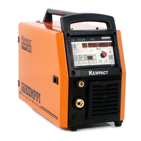
Kemppi Kempact Pulse 3000 Operation instructions
