Cloos Micro Pulse 300 Guide

operating instruction
and spare parts
Micro Pulse 300
01/15 Rev.0
- EN -

Carl Cloos Schweisstechnik GmbH
Industriestrasse
35708 Haiger
Germany
Telefon (0 27 73) 85-0
Telefax (0 27 73) 85-275
E-Mail: [email protected]
Internet: http://www.cloos.de
RW - FP - Rev.0
Ausgabedatum 3. 02 2015
Keep for further use.

CARL CLOOS Schweisstechnik GmbH
Industriestrasse
35708 Haiger/Germany
Tel. +49 (0)2773/85-0
Fax. +49 (0)2773/85-275
mail: [email protected]
www.cloos.de
EU declaration of conformity No. CMM0516QNMIP3_01
Product description: MIG/MAG welding machine
Model name:
QINEO MICRO PULSE 300
Serial number: Refer to the nameplate on the back of the device
Manufacturer: CARL CLOOS Schweisstechnik GmbH
Address:
The manufacturer bears sole responsibility for issuing the declaration of conformity.
Low Voltage Directive:
EMC Directive:
RoHS Directive:
- EN 60974-1 Arc Welding Equipment
Part 1: Welding Power Sources
- EN 60974-5 Arc Welding Equipment
Part 5: Wire Feed Units
- EN 60974-10 Arc Welding Equipment
Part 10: Requirements of Electromagnetic Compatibility (EMC)
Signed for and in the name of:
CARL CLOOS Schweisstechnik GmbH
35708 Haiger, 30/05/16
Signature: Gerald Mies
Identification of signatory: Managing director
Agreement of the product stated with the regulations in the directives applied is verified with conformance to the
following standards and regulations:
Major conversions and add-ons which are not carried out by the manufacturer or the manufacturer’s authorised
representative(s) result in termination of this declaration of conformity.
Industriestrasse 22-36
35708 Haiger
Germany
2014/35/EU Directive of the European Parliament and of the Council of 26 February 2014 on the
harmonisation of laws of Member States relating to the making available on the market of electrical
equipment designed for use within certain voltage limits; Official Journal of the EU L96, 29/03/2014,
Pages 357 - 374
2014/30/EU Directive of the European Parliament and of the Council of 26 February 2014 on the
harmonisation of laws of Member States relating to electromagnetic compatibility; Official Journal of the
EU L96, 29/03/2014, Pages 79 - 106
2011/65 /EU Directive of the European Parliament and of the Council of 8 June 2011 on the restriction
of use of certain hazardous substances in electrical and electronic equipment; Official Journal of the EU
L174, 01/07/2011, Pages 88 - 110
The aforementioned products covered by the declaration satisfy the relevant
statutory provisions of the Union:

Micro Pulse 300
Cod.006.0001.1721
22/04/2014 v2.0
ENGLISH
3/50
CONTENTS
1INTRODUCTION .....................................................................................................................................................................................5
2INSTALLATION ......................................................................................................................................................................................6
2.1 CONNECTIONS TO THE ELECTRICAL MAINS NETWORK.................................................................................................................6
2.2 FRONT PANEL........................................................................................................................................................................................6
2.3 REAR PANEL..........................................................................................................................................................................................6
2.4 PREPARING FOR MMA WELDING........................................................................................................................................................7
2.5 PREPARING FOR TIG WELDING ..........................................................................................................................................................8
2.6 PREPARING FOR MIG/MAG WELDING ...............................................................................................................................................9
2.6.1 WIRE SPOOL POSITIONING.......................................................................................................................................................................................... 9
2.6.2 POSITIONING THE WIRE IN THE WIRE FEEDER........................................................................................................................................................ 9
2.6.3 CONNECTIONS TO SOCKETS .................................................................................................................................................................................... 10
3COMMISSIONING.................................................................................................................................................................................12
3.1 USER INTERFACE ...............................................................................................................................................................................12
3.2 UNIT POWER-UP..................................................................................................................................................................................13
3.3 RESET (LOAD FACTORY SETTINGS) ................................................................................................................................................14
3.3.1 PARTIAL RESET........................................................................................................................................................................................................... 14
3.3.2 TOTAL RESET .............................................................................................................................................................................................................. 14
3.4 SET-UP (INITIAL SET-UP OF THE WELDING POWER SOURCE).....................................................................................................15
3.5 LOCKING PROCEDURE.......................................................................................................................................................................16
3.6 GAS FLOW ADJUSTMENT...................................................................................................................................................................17
3.7 TORCH LOADING.................................................................................................................................................................................17
3.8 ALARMS MANAGEMENT .....................................................................................................................................................................18
4WELDING SETTINGS...........................................................................................................................................................................19
4.1 TORCH TRIGGER MODES ..................................................................................................................................................................19
4.1.1 2T MIG/MAG WELDING................................................................................................................................................................................................ 19
4.1.2 2T SPOT MIG/MAG WELDING..................................................................................................................................................................................... 19
4.1.3 4T MIG/MAG WELDING................................................................................................................................................................................................ 19
4.1.4 4T B-L MIG/MAG WELDING ......................................................................................................................................................................................... 19
4.1.5 4T/3L MIG/MAG WELDING........................................................................................................................................................................................... 19
4.1.6 4T B-L/3L MIG/MAG WELDING .................................................................................................................................................................................... 20
4.2 SELECTION OF THE WELDING MODE AND TORCH TRIGGER PROCEDURE...............................................................................20
4.3 WELDING PARAMETERS ....................................................................................................................................................................21
4.4 PARAMETERS ACTIVATION ...............................................................................................................................................................24
5CHARACTERISTICS OF THE MENU LEVELS....................................................................................................................................25
5.1 1ST LEVEL............................................................................................................................................................................................25
5.2 2ND LEVEL ...........................................................................................................................................................................................25
5.3 3RD LEVEL ...........................................................................................................................................................................................26
6WELDING SETTINGS...........................................................................................................................................................................27
6.1 ELECTRODE WELDING (MMA) ...........................................................................................................................................................27
6.1.1 PARAMETERS SETTING.............................................................................................................................................................................................. 27
6.1.2 PARAMETERS SETTING: (2ND LEVEL)...................................................................................................................................................................... 27
6.2 DC TIG WELDING.................................................................................................................................................................................27
6.2.1 PARAMETERS SETTING.............................................................................................................................................................................................. 27
6.2.2 PARAMETERS SETTING: (2ND LEVEL)...................................................................................................................................................................... 27
6.3 MIG/MAG WELDING.............................................................................................................................................................................28
6.3.1 WELDING CURVES SELECTION................................................................................................................................................................................. 28
6.3.2 SPECIAL CURVES: HS AND POWER FOCUS............................................................................................................................................................ 28
6.4 MANUAL MIG/MAG WELDING.............................................................................................................................................................29
6.4.1 MANUAL MIG/MAG PARAMETERS SETTING (1ST LEVEL): INDUCTANCE SETTING............................................................................................ 29
6.4.2 PARAMETERS SETTING: (1ST LEVEL) ...................................................................................................................................................................... 29
6.4.3 MANUAL MIG/MAG PARAMETERS SETTING (2ND LEVEL) ..................................................................................................................................... 29
6.5 SYNERGIC MIG/MAG WELDING .........................................................................................................................................................30
6.5.1 SYNERGIC MIG/MAG PARAMETERS SETTING (1ST LEVEL): SYNERGIC CURVE SETTING............................................................................... 30
6.5.2 PARAMETERS SETTING: (1ST LEVEL) ...................................................................................................................................................................... 30
6.5.3 SYNERGIC MIG/MAG PARAMETERS SETTING (2ND LEVEL).................................................................................................................................. 31
6.6 PULSED SYNERGIC MIG/MAG WELDING..........................................................................................................................................32
6.6.1 PULSED SYNERGIC MIG/MAG PARAMETERS SETTING (1ST LEVEL): SYNERGIC CURVE SETTING................................................................ 32
6.6.2 PARAMETERS SETTING: (1ST LEVEL) ...................................................................................................................................................................... 32
6.6.3 PULSED SYNERGIC MIG/MAG PARAMETERS SETTING (2ND LEVEL) .................................................................................................................. 33
6.7 DOUBLE PULSED SYNERGIC MIG/MAG WELDING..........................................................................................................................34
6.7.1 DOUBLE PULSED SYNERGIC MIG/MAG PARAMETERS SETTING (1ST LEVEL): SYNERGIC CURVE SETTING................................................ 34
6.7.2 PARAMETERS SETTING: (1ST LEVEL) ...................................................................................................................................................................... 34
6.7.3 DOUBLE PULSED SYNERGIC MIG/MAG PARAMETERS SETTING (2ND LEVEL) .................................................................................................. 35
6.8 JOBS MANAGEMENT...........................................................................................................................................................................36
6.8.1 SAVING A JOB.............................................................................................................................................................................................................. 36

Cod.006.0001.1721
22/04/2014 v2.0
ENGLISH
Micro Pulse 300
4/50
6.8.2 LOADING A USER JOB.................................................................................................................................................................................................36
6.8.3 DELETING A JOB ..........................................................................................................................................................................................................37
7TECHNICAL DATA...............................................................................................................................................................................38
8SPARE PARTS .....................................................................................................................................................................................40
8.1 MICRO PULSE 300...............................................................................................................................................................................40
8.2 WIRE FEEDER MOTOR .......................................................................................................................................................................42
8.3 WIRE FEEDER ROLLS.........................................................................................................................................................................44
9ELECTRICAL DIAGRAM......................................................................................................................................................................45
Micro Pulse 300
Cod.006.0001.1721
22/04/2014 v2.0
ENGLISH
5/50
1INTRODUCTION
IMPORTANT!
This handbook must be consigned to the user prior to
installation and commissioning of the unit.
Read the "General prescriptions for use" handbook supplied
separately from this handbook before installing and
commissioning the unit.
The meaning of the symbols in this manual and the associated
precautionary information are given in the "General
prescriptions for use”.
If the "General prescriptions for use" are not present, it is
mandatory to request a replacement copy from the manufacturer
or from your dealer.
Retain these documents for future consultation.
KEY
DANGER!
This pictogram warns of danger of death or serious injury.
WARNING!
This pictogram warns of a risk of injury or damage to property.
CAUTION!
This pictogram warns of a potentially hazardous situation.
INFORMATION
This pictogram gives important information concerning the execution
of the relevant operations.
This symbol identifies an action that occurs automatically as a
result of a previous action.
This symbol identifies additional information or a reference to a
different section of the manual containing the associated
information.
§
This symbol identifies a reference to a chapter of the manual.
NOTES
The figures in this manual are purely guideline and the images may
contain differences with respect to the actual equipment to which they
refer.
INTRODUCTION
Micro Pulse 300 is a compact and rugged three-phase, synergic
inverter power source for MIG/MAG, MMA and TIG Lift welding.
Easy to transport, only 22 kg , it is the best option for maintenance
and repair on fi eld, shipyard and off -shore operations.
Polarity change allows welding with self shielded wires.
Available MIG/MAG mode: manual, synergic, pulsed synergic and
double pulsed synergic.
Pulsed Synergic and Double Pulsed Synergic modes ensure excellent
appearance of the weld bead, without spatter or deformation when
welding aluminium, stainless steel and regular steels.
A broad range of synergic MIG-MAG programs facilitates the selection
of precise welding parameters rapidly and using all types of wire.
A perfect wire feeding is guaranteed thanks to a 4-rolls motor drive
included in Micro Pulse 300.
The fan is turned on only during welding, at the end of the welding
process it remains on for a fixed period of time according to welding
conditions.
The fan is nonetheless controlled by specific thermal sensors that
guarantee a correct cooling of the machine.
Accessories that can be connected to the unit:
-Manual remote controller for remote adjustment of the welding
current.

Cod.006.0001.1721
22/04/2014 v2.0
ENGLISH
Micro Pulse 300
6/50
2INSTALLATION
DANGER!
Lifting and positioning
Read the warnings highlighted by the following symbols in the
“General prescriptions for use”.
2.1 CONNECTIONS TO THE ELECTRICAL MAINS
NETWORK
The characteristics of the mains power supply to which the equipment
shall be connected are given in the section entitled “Technical data”
on page 38.
The machine can be connected to motorgenerators provided their
voltage is stabilised.
Connect/disconnect the various devices with the machine switched
off.
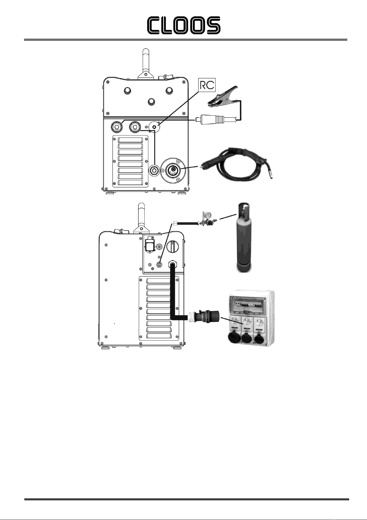
2.2 FRONT PANEL
1.
Negative pole welding socket.
2.
Positive pole welding socket.
3.
Polarity selector cable.
4.
EURO TORCH welding socket.
5.
Remote controller connector.
2.3 REAR PANEL
1.
Cooler power feeding connector.
Voltage: 400 Va.c.
Current Output: 0.8 A
IP protection rating: IP20 (cap open) / IP66 (cap closed)
2.
Wire feed motor power transformer fuse.
Type: Delayed acting (T)
Amperage: 1 A
Voltage: 500 V
3.
Welding power source ON/OFF switch.
4.
Mains protection ON LED.
This LED illuminates if an incorrect operating condition occurs:
-absence of a phase in the power supply line.
5.
Connector for gas feed hose:
cylinder power source
6.
Power cable.
Total length (including internal part): 3,5 m
Number and cross section of wires: 4 x 2,5 mm2
Power plug type: not supplied
4
5
3
2
1
5
3
2
4
1
6
4
Micro Pulse 300
Cod.006.0001.1721
22/04/2014 v2.0
ENGLISH
7/50
2.4 PREPARING FOR MMA WELDING
1.
Set the welding power source ON/OFF switch to “O” (unit de-
energized).
2.
Plug the power cable plug into a mains socket outlet.
3.
Choose the electrode based on the type of material and thickness
of the workpiece to be welded.
4.
Insert the electrode in the electrode holder.
5.
Connect the plug of the electrode holder clamp to the welding
socket on the basis of the polarity required by the type of electrode
in question.
6.
Connect the plug of the ground clamp to the welding socket on the
basis of the polarity required.
7.
Connect the earth clamp to the workpiece being processed.
DANGER!
Electric shock hazard!
Read the warnings highlighted by the following symbols in the
“General prescriptions for use”.
8.
Set the welding power source ON/OFF switch to “I” (unit
powered).
9.
Select the following welding mode on the user interface: MMA
10.
Set the required welding parameter values on the user interface.
When the remote controller [RC] is connected and the relative
locking screw is tightened, welding current can be adjusted using
the remote controller.
The system is ready to start welding.

Cod.006.0001.1721
22/04/2014 v2.0
ENGLISH
Micro Pulse 300
8/50
2.5 PREPARING FOR TIG WELDING
1.
Set the welding power source ON/OFF switch to “O” (unit de-
energized).
2.
Plug the power cable plug into a mains socket outlet.
3.
Connect the gas hose from the welding gas cylinder to the rear
gas socket.
4.
Open the cylinder gas valve.
5.
Connect the TIG torch plug to the EURO TORCH welding socket.
6.
Choose the electrode based on the type of material and thickness
of the workpiece to be welded.
7.
Insert the electrode in the TIG torch.
8.
Connect the plug of the polarity selector cable to the welding
socket on the basis of the polarity required.
9.
Connect the plug of the ground clamp to the welding socket on the
basis of the polarity required.
10.
Connect the earth clamp to the workpiece being processed.
11.
Set the welding power source ON/OFF switch to “I” (unit
powered).
12.
Select the following welding mode on the user interface: DC TIG
13.
Press the torch trigger with the torch well clear of any metal parts.
This serves to open the gas solenoid valve without striking the
welding arc.
14.
Use the flow control valve to adjust the flow of gas as required
while the gas is flowing out.
15.
Set the required welding parameter values on the user interface.
When the remote control pedal is connected and the relative
locking screw is tightened the welding current will vary in relation
to the pressure exerted on the pedal.
The system is ready to start welding.
Micro Pulse 300
Cod.006.0001.1721
22/04/2014 v2.0
ENGLISH
9/50
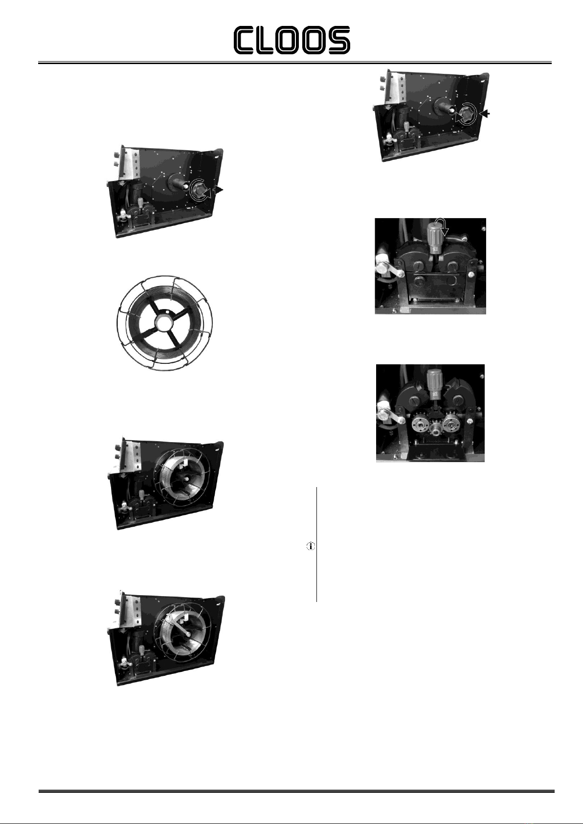
2.6 PREPARING FOR MIG/MAG WELDING
2.6.1 WIRE SPOOL POSITIONING
1.
Open the unit side door to gain access to the spool compartment.
2.
Unscrew the cap of the spool holder.
3.
If necessary, fit an adapter for the wire spool.
4.
Choose the wire on the basis of the workpiece thickness and
material type.
5.
Fit the spool in the spool holder, ensuring it is located correctly.
6.
Adjust the spool holder braking system by tightening/loosening the
screw in such a way that the wire feed force is not excessive and
when the spool stops rotating no excess wire is released.
7.
Refit the plug.
2.6.2 POSITIONING THE WIRE IN THE WIRE FEEDER
1.
Lower the wire feeder pressure devices.
2.
Raise the wire feeder pressure arms.
3.
Remove the protective cover.
4.
Check that the feed rolls are suitable for the wire gauge.
(See § 8.3 page 44.)
The diameter of the roll groove must be compatible with the
diameter of the welding wire.
The roll must be of suitable shape in relation to the composition of
the wire material.
The groove must feature a "U" profile for soft materials (Aluminium
and its alloys, CuSi3).
The groove must be "V" shaped for harder materials (SG2-SG3,
stainless steels).
Rolls with a knurled groove profile are available for flux-cored wire.
Cod.006.0001.1721
22/04/2014 v2.0
ENGLISH
Micro Pulse 300
10/50
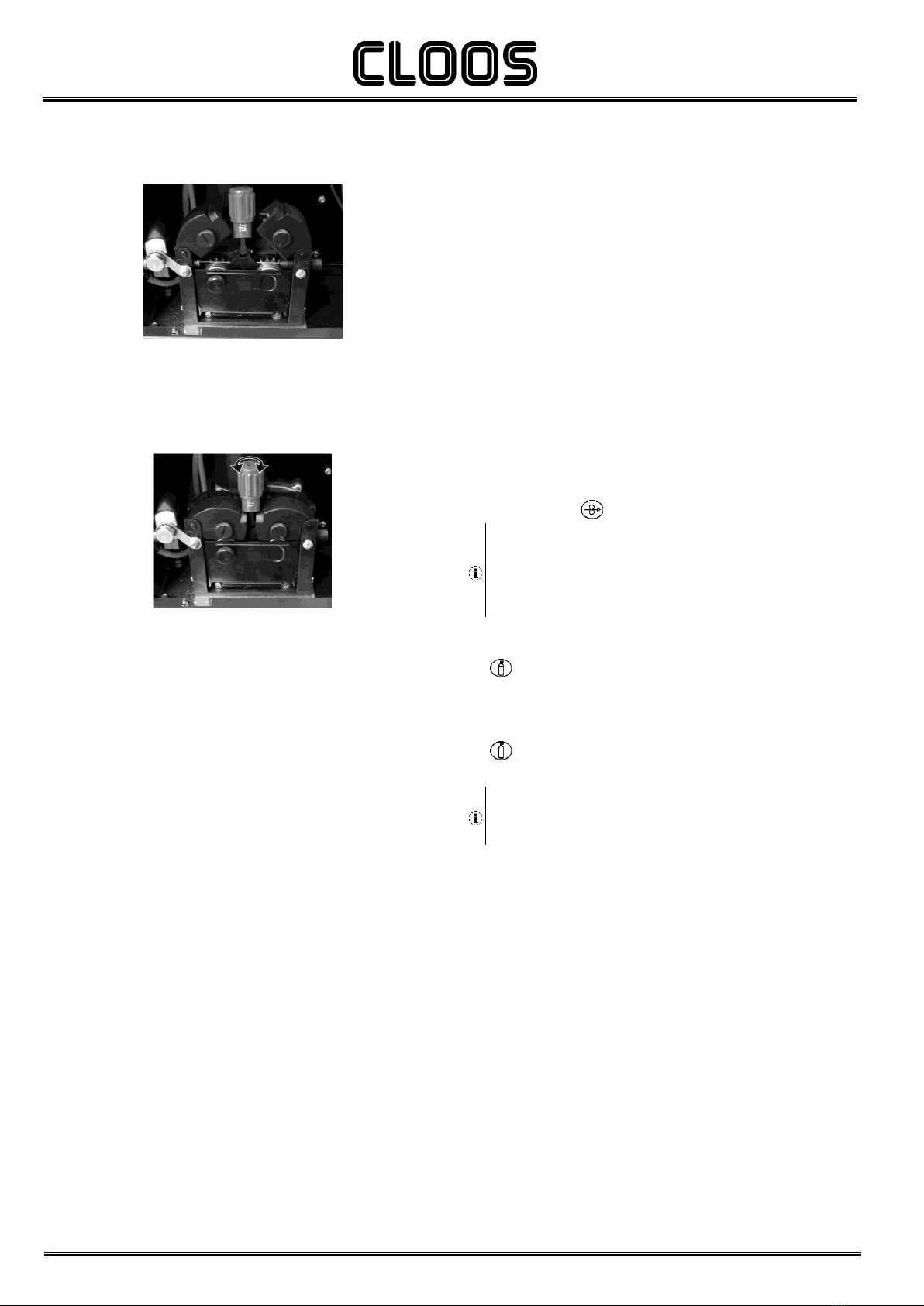
5.
Feed the wire between the wire feeder rolls and insert it into the
MIG/MAG TORCH connector plug.
6.
Make sure the wire is located correctly in the roll grooves.
7.
Close the wire feeder pressure arms.
8.
Adjust the pressure system so that the arms press the wire with a
force that does not deform it while also ensuring constant feed rate
without slipping.
9.
Refit the protective cover.
10.
Close the spool compartment door in the side of the unit.
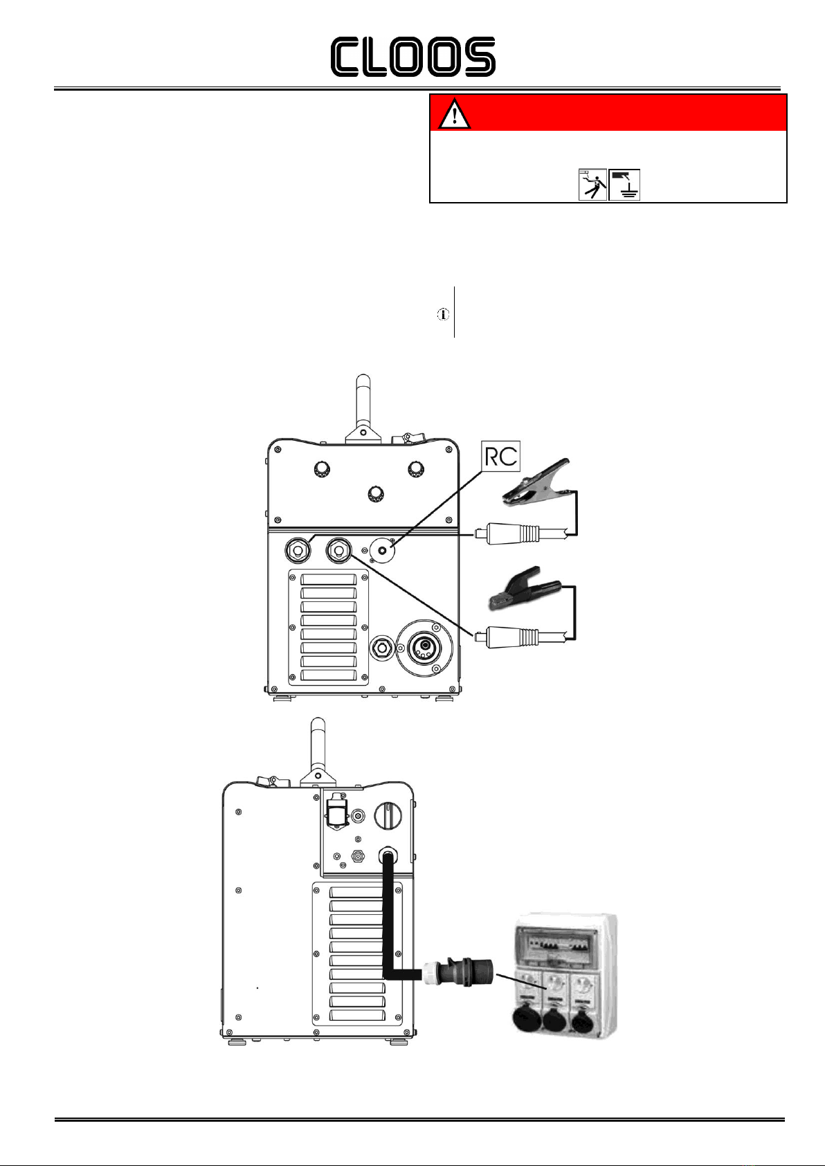
2.6.3 CONNECTIONS TO SOCKETS
1.
Set the welding power source ON/OFF switch to “O” (unit de-
energized).
2.
Plug the power cable plug into a mains socket outlet.
3.
Connect the gas hose from the welding gas cylinder to the relative
socket.
4.
Open the cylinder gas valve.
5.
Connect the MIG/MAG torch plug to the EURO TORCH welding
socket.
6.
Connect the plug of the ground clamp to the welding socket on the
basis of the polarity required.
7.
Connect the plug of the polarity selector cable to the welding
socket on the basis of the polarity required.
8.
Connect the earth clamp to the workpiece being processed.
9.
Set the welding power source ON/OFF switch to “I” (unit
powered).
10.
Select the following welding mode on the user interface:
MIG/MAG
11.
Feed the wire through the torch until it protrudes from the tip,
pressing button on the unit's user interface.
The insertion speed is 2.0 m/min for 3 seconds, subsequently
increasing to 15 m/min. When the button is released wire feed is
interrupted.
This function produces a slower feed rate and hence greater
precision when inserting the wire when it enters the torch nozzle.
12.
Select the torch trigger procedure on the user interface.
13.
Open the gas solenoid valve by pressing and releasing the button
.
14.
Use the flow control valve to adjust the flow of gas as required
while the gas is flowing out.
15.
Close the gas solenoid valve by pressing and releasing the button
.
16.
Set the required welding parameter values on the user interface.
On connecting and enabling a remote controller [RC] certain
settings can be modified from said controller without having to
take action on the user interface of the welding power source.
The system is ready to start welding.
Micro Pulse 300
Cod.006.0001.1721
22/04/2014 v2.0
ENGLISH
11/50

Cod.006.0001.1721
22/04/2014 v2.0
ENGLISH
Micro Pulse 300
12/50
3COMMISSIONING
3.1 USER INTERFACE
CODE
SYMBOL
DESCRIPTION
L1
MIG/MAG mode: When this LED illuminates the following parameter can be set: WELDING THICKNESS
L2
MIG/MAG mode: When this LED illuminates the following parameter can be set: WELDING CURRENT
L3
MIG/MAG mode: When this LED illuminates the following parameter can be set: WIRE FEED RATE
L4
Illuminates to show a value in the following unit of measurement: AMPERES
L5
Illuminates to show a value in the following unit of measurement: METRES PER MINUTE
L6
Illuminates to show the last voltage and current values measured during welding.
The LED switches off when a new welding procedure is started, or when any of the welding settings is modified.
L7
Illuminates to show a value in the following unit of measurement: MILLIMETRES
L8
Illuminates to show a value in the following unit of measurement: VOLTS
L9
This LED illuminates to show an anomaly in the operating conditions.
See § 3.8 ALARMS MANAGEMENT page 18.
L10
This LED illuminates to confirm the presence of power on the output sockets.
L11
Illumination shows that the following function has been activated: 2 stroke procedure.
A flashing signal means the following function is activated: 2 stroke spot procedure.
L12
Illumination shows that the following function has been activated: 4 stroke procedure.
L13
Illumination shows that the following function has been activated: 3 levels procedure.
L14
This LED illuminates to show that the following welding mode is selected: MMA
L15
This LED illuminates to show that the following welding mode is selected: TIG CONTINUOUS
L16
This LED illuminates to show that the following welding mode is selected: MANUAL MIG/MAG - SYNERGIC MIG/MAG
L17
This LED illuminates to show that the following welding mode is selected: PULSED SYNERGIC MIG/MAG
L18
This LED illuminates to show that the following welding mode is selected: DOUBLE PULSED SYNERGIC MIG/MAG

Micro Pulse 300
Cod.006.0001.1721
22/04/2014 v2.0
ENGLISH
13/50
CODE
SYMBOL
DESCRIPTION
D1
During illumination of the following LEDs: / /
The display shows the value of the selected parameter.
Welding: The display shows the effective amperes value during welding.
HOLD function: The display shows the latest measured current value.
D2
Parameters/functions setting: The displays show the value of the following parameter: WELDING VOLTAGE
Parameters/functions setting (Synergic MIG/MAG welding): The display shows the arc correction value imposed by
the operator with respect to the default value of the synergic curve. Arc correction is performed by means of encoder E2.
After 3 seconds the display shows the effective volts value during welding.
Welding: The display shows the effective voltage value during welding.
HOLD function: The display shows the latest measured voltage value.
D3
Data setting: The display shows the various welding menus relative to the selected processes.
The display shows the selected parameter.
S1
The button selects one of the following settings: WIRE FEED RATE - WELDING CURRENT - THICKNESS
S2
Press the button once to select the parameters of the first level menu.
Hold down the button for 3 seconds to gain access to the second level menu.
Hold down the button at the time of power-on to gain access to the SETUP menu.
S3
The button scrolls the selection made on the menus upwards or to the right.
S4
The button scrolls the selection made on the menus downwards or to the left.
S5
The button restores the main menu of display D3, starting from any other page.
The button serves to exit any menu without saving any changes.
S6
This button selects the welding mode.
S7
This button selects the torch trigger procedure.
See § 4.1 page 19.
S8
Press and release: the button opens the JOBs upload menu.
Hold down for 3 seconds: the button opens the JOBs save and delete menu.
S9
This button opens the gas solenoid valve to fill the circuit and calibrate the pressure with the regulator on the gas
cylinder.
GAS menu function: Hold down the button for 3 seconds to open the menu.
S10
MIG/MAG mode: this button activates wire feed to insert it through the MIG/MAG torch.
E1
Data setting: The encoder adjusts the main welding (and synergy) parameter, shown on the following display: D1
E2
Manual MIG/MAG mode: The encoder adjusts the welding voltage, and the relative value is shown, in volts, on the
following display: D2
Synergic MIG/MAG mode: The encoder is used to correct the factory-set value of the selected synergic curve, the value
of which is shown on the following display: D2
E3
The encoder changes the setting of the selected parameter shown on the following display: D3
The selected parameter is shown by the following symbol:
3.2 UNIT POWER-UP
Set the welding power source ON/OFF switch to “I” to switch on the unit.
MOTOR
MICROPULSE 302
FW: XX.XX.XXX
PROGRAM
UPDATE
MICRO PULSE
302
FW: YY.YY.YYY
POWER SOURCE
OK
The message appears on the following displays: D3
XX.XX.XXX= motor board software version.
YY.YY.YYY= pulsed board software version.
First power-up or power-ups following a RESET procedure
The welding power source sets up for welding with the factory presets.
Subsequent power-ups
The welding power source sets up for welding in the latest stable welding configuration that was active at the time of power-off.
During power-up all functions are inhibited and the following displays remain blank: D1-D2
Cod.006.0001.1721
22/04/2014 v2.0
ENGLISH
Micro Pulse 300
14/50
3.3 RESET (LOAD FACTORY SETTINGS)
The reset procedure involves complete restoration of the default values, parameters and memory settings set in the factory.
The reset procedure is useful in the following cases:
-Too many changes made to the welding parameters so user finds it difficult to restore defaults.
-Unidentified software problems that prevent the welding power source from functioning correctly.
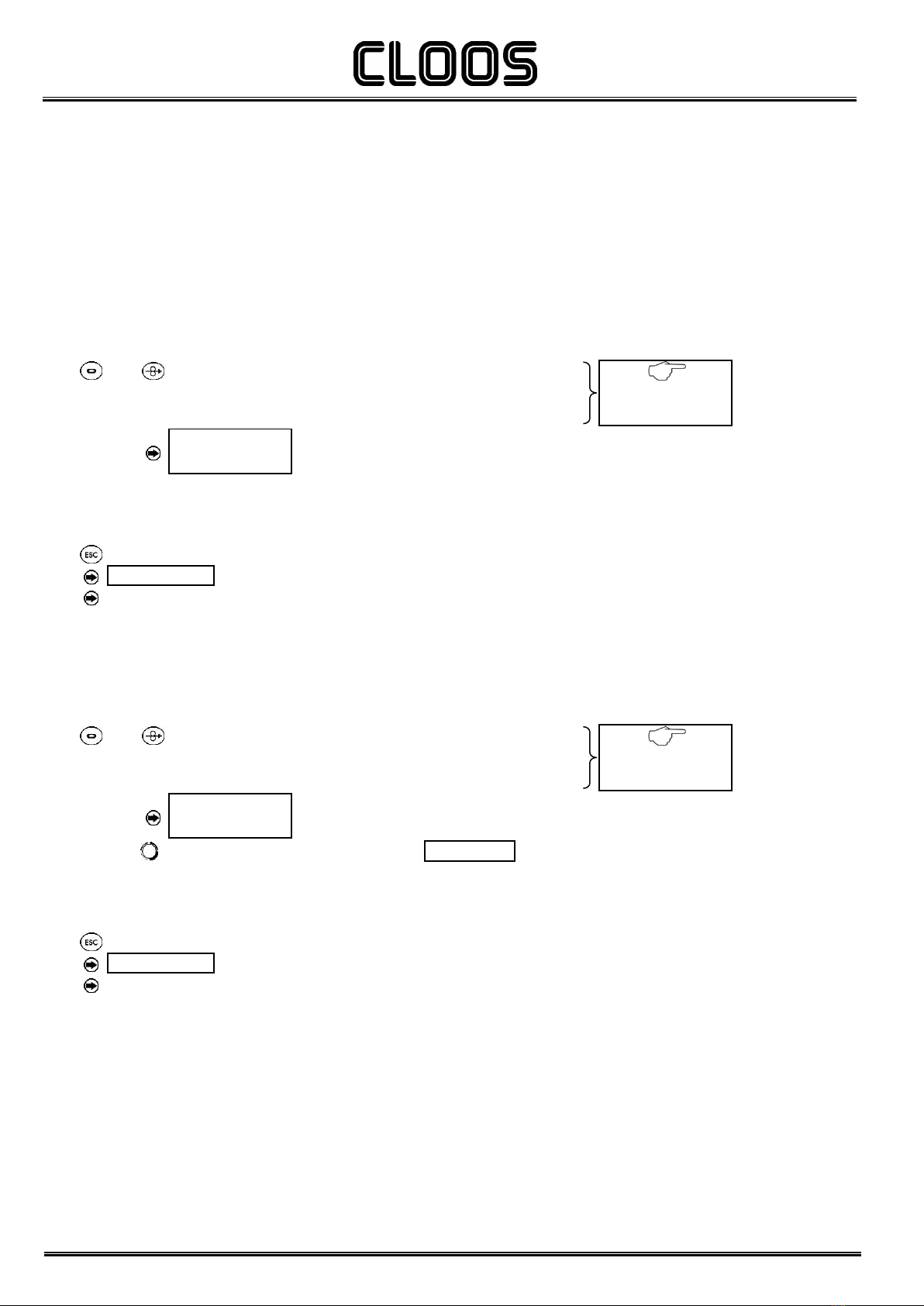
3.3.1 PARTIAL RESET
The reset procedure involves restoration of the parameter values and settings, except the following settings:
-Settings of the SETUP menu.
-saved JOBS.
-Set language.
Set the welding power source ON/OFF switch to “O” to switch the unit off.
S1
S10
Hold down both buttons simultaneously.
Set the welding power source ON/OFF switch to “I” to switch on the unit.
SIMULTANEOUS ACTIONS
PARTIAL RESET SETUP
SELECT
RESET TYPE
The message appears on the following displays: D3
Exit without confirmation
Set the welding power source ON/OFF switch to “O” to switch the unit off.
Set the welding power source ON/OFF switch to “I” to switch on the unit.
Exit with confirmation
S5
Press the button.
MEMORY CLEANING
The message appears on the following displays: D3
This action will automatically close the menu.
Wait for the memory clear procedure to terminate.
3.3.2 TOTAL RESET
The reset procedure involves complete restoration of the default values, parameters and memory settings set in the factory.
All memory locations will be reset and hence all your personal welding settings will be lost!
S1
S10
Hold down both buttons simultaneously.
Set the welding power source ON/OFF switch to “I” to switch on the unit.
SIMULTANEOUS ACTIONS
PARTIAL RESET SETUP
SELECT
RESET TYPE
The message appears on the following displays: D3
E1
Select the following setting with the encoder:
FACTORY SETUP
Exit without confirmation
Set the welding power source ON/OFF switch to “O” to switch the unit off.
Set the welding power source ON/OFF switch to “I” to switch on the unit.
Exit with confirmation
S5
Press the button.
MEMORY CLEANING
The message appears on the following displays: D3
This action will automatically close the menu.
Wait for the memory clear procedure to terminate.

Micro Pulse 300
Cod.006.0001.1721
22/04/2014 v2.0
ENGLISH
15/50
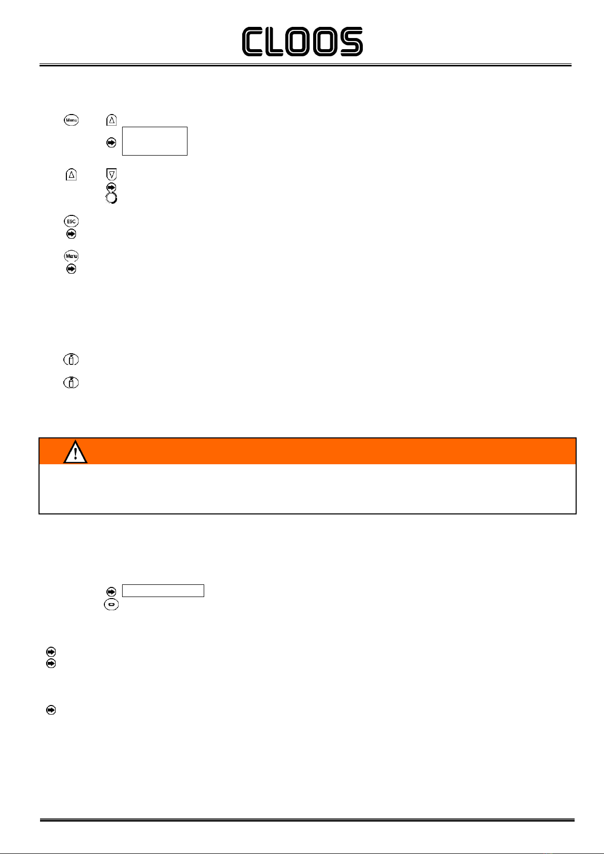
3.4 SET-UP (INITIAL SET-UP OF THE WELDING POWER SOURCE)
With locked status active it is not possible to access this function.
§ 3.5 LOCKING PROCEDURE
Set the welding power source ON/OFF switch to “O” to switch the unit off.
Set the welding power source ON/OFF switch to “I” to switch on the unit.
S2
Hold down the button.
Perform this operation before the message “SYNCHRONISATION”
appears on the following display: D3
SET UP x/y
The message appears on the following displays: D3
x=
number of the currently displayed menu page.
y=
total number of menu pages.
S3
S4
Use these buttons to scroll through the list of settings to edit.
Activation of the LOCK STATUS setting calls for a specific procedure.
§ 3.5 LOCKING PROCEDURE
E1
Using the encoder, edit the value of the selected setting.
S4
Press any button to save the setting and quit the menu.
The unit restarts with the power-up procedure.
Tab. 1 - Setup settings
MENU PAGE
SETTING
MIN
DEFAULT
MAX
SET UP 1/7
LANGUAGE
ENGLISH
ITALIANO
FRANÇAIS
DEUTSCH
ESPAÑOL
PORTUGUES
DUTCH
CESKY
SRBSKI
POLSKI
SUOMI
SET UP 2/7
COOLING TYPE
ON
OFF
AUTO
SET UP 3/7
DISPLAY CONTRAST
0 %
80 %
100 %
SET UP 4/7
CONTROL TYPE
OFF
OFF
RC06
OFF
RC03
RC04
RC05
RC06
SET UP 5/7
LOCK STATUS
OFF
OFF
LOCK 3
OFF
LOCK 1
LOCK 2
LOCK 3
SET UP 6/7
ARC CORRECTION
VOLTS
VOLTS
m/min
SET UP 7/7
PUSH-PULL
OFF
OFF
ON
COOLING TYPE
ON=
-The cooler is always running when the power source is switched on. This mode is preferable for heavy duty and automatic welding
procedures.
OFF=
-The cooler is always disabled because an air-cooled torch is in use.
AUTO=
-When the unit is switched on the cooler is switched on for 15 s. During welding procedures the cooler runs constantly. When welding
is terminated the cooler continues to run for 90 s + a number of seconds equivalent to the average current value shown using the
HOLD function.

Cod.006.0001.1721
22/04/2014 v2.0
ENGLISH
Micro Pulse 300
16/50
CONTROL TYPE
OFF=
No remote controller enabled.
RC03=
The unit is enabled to receive commands from a remote control equipped with 1 potentiometer.
RC04=
The unit is enabled to receive commands from a remote control equipped with 2 potentiometer.
RC05=
The unit is enabled to receive commands from a remote control equipped with 1 UP/DOWN lever.
RC06=
The unit is enabled to receive commands from a remote control equipped with 2 UP/DOWN levers.
LOCK STATUS
OFF=
All adjustments enabled.
LOCK 1 - LOCK 2 - LOCK 3=
All adjustments are disabled with the exceptions shown in Tab. 2 page 16.
3.5 LOCKING PROCEDURE
The procedure inhibits unit adjustments, allowing the user to modify only certain settings depending on the selected lock status.
The procedure is used to prevent accidental alteration of the unit settings and welding settings by the operator.
Enabling
If no locking status is selected (LOCKED STATUS = OFF) and if you wish to set up a limitation on use of the welding power source, display page
5/7 of the SETUP menu.
E3
Use the encoder to select the required lock status.
S2
Press the button to confirm.
WRITE PASSWORD
0000
The message appears on the following displays: D3
Default password: 0000
Enter the 4 digit numerical password.
S3
S4
Use these keys to select the digit to be modified.
The selected digit blinks.
E3
Use this encoder to select the value.
Exit without confirmation
S5
Press the button.
This action will automatically close the menu.
Exit with confirmation
S2
Press the button.
The unit restarts with the power-up procedure.
The password becomes the active password. Make a note of the password you set!
Tab. 2 - Functions not disabled by Locks
LOCKED
STATUS
SELECTED
ADJUSTMENT DEVICE
USER INTERFACE
RC03
RC04
RC05
RC06
OFF
All adjustments enabled.
All adjustments enabled.
All adjustments enabled.
All adjustments enabled.
All adjustments enabled.
1
Selection of torch trigger procedure (button S7)
Display of main welding parameters (button S1)
Arc correction (encoder E2)
Wire insertion (button S10)
Gas test (button S9)
Arc correction
(Potentiometer Pot2)
Arc correction
(UP/DOWN lever 2)
2
Selection of torch trigger procedure (button S7)
Display of main welding parameters (button S1)
Arc correction (encoder E2)
Synergy (encoder E1)
Wire insertion (button S10)
Gas test (button S9)
All adjustments enabled.
All adjustments enabled.
All adjustments enabled.
All adjustments enabled.
3 (*1)
Selection of torch trigger procedure (button S7)
Display of main welding parameters (button S1)
JOB selection (encoder E2)
Wire insertion (button S10)
Gas test (button S9)
Scroll JOBS (UP/DOWN
lever 1)
Scroll JOBS (UP/DOWN
lever 1)
*1:
The LOCK 3 setting becomes active only when a JOB is loaded. When no JOB is loaded, the user interface is completely unlocked.
Micro Pulse 300
Cod.006.0001.1721
22/04/2014 v2.0
ENGLISH
17/50
Disabling
If a lock status is selected, you can only edit parameters permitted by the currently active lock status.
If you cannot recall the password the only way to exit locked status is to perform the welding power source RESET procedure.
S2
S3
Hold down these buttons simultaneously for 3 seconds.
LOCK …
WRITE PASSWORD
0000
The message appears on the following displays: D3
Enter the active 4 digit numerical password.
S3
S4
Use these keys to select the digit to be modified.
The selected digit blinks.
E3
Use this encoder to select the value.
Exit without confirmation
S5
Press the button.
This action will automatically close the menu.
Exit with confirmation
S2
Press the button.
The unit restarts with the power-up procedure.
Quit locked status.
3.6 GAS FLOW ADJUSTMENT
When the unit is powered on the solenoid valve opens for 1 second.
This serves to fill the gas circuit.
S9
Open the gas solenoid valve by pressing and releasing the button.
Adjust the pressure of gas flowing from the torch by means of the flow meter connected to the gas cylinder.
S9
Close the gas solenoid valve by pressing and releasing the button.
The solenoid valve closes automatically after 30 seconds.
3.7 TORCH LOADING
WARNING!
Make sure the torch in use is correctly sized in relation to the welding current required and for the available and selected cooling type. This
prevents the risk of burns to which the operator is potentially exposed, potential faults, and irreversible damage to the torch and the system.
If a torch is installed or replaced while the unit is running, the circuit of the newly installed must be filled with coolant to avoid the risk of damage
to the torch in the case of high voltage arc strikes without any liquid in the circuit.
Power-up with operation of the cooler set to "ON" or "AUTO" mode
A check is performed automatically of the presence of liquid in the cooling circuit and the cooler is switched on for 30 seconds.
If the coolant circuit is full, the power source sets up in the most recent stable welding configuration.
If the coolant circuit is not full, all functions are inhibited and there will be no output power present.
COOLING SYSTEM TEST
The message appears on the following displays: D3
(any)
Press the button or torch trigger to repeat the checking procedure for an additional 30 seconds.
If the problem persists rectify the cause of the alarm.
Power-up with operation of the cooler set to "OFF"
Operation of the cooler and the cooler alarm are disabled.
Welding is performed without liquid cooling of the torch.
Torch change-over with operation of the cooler set to "AUTO"
Press and release the torch trigger.
This serves to start the cooler for 80 seconds to fill the torch cooling circuit.

Cod.006.0001.1721
22/04/2014 v2.0
ENGLISH
Micro Pulse 300
18/50
3.8 ALARMS MANAGEMENT
This LED illuminates if an incorrect operating condition occurs.
An alarm message appears on the following display: D3
Tab. 3 - Alarm messages
MESSAGE
MEANING
EVENT
CHECKS
WARNING POWER SOURCE
Overheating alarm
Indicates tripping of the welding power source
thermal protection.
Leave the unit running so that the overheated
components cool as rapidly as possible.
When the unit has cooled, the welding power
source will reset automatically.
All functions
disabled.
Exceptions:
-Cooling fan.
-Cooler alarm.
-Make sure that the power required by the
welding process is lower than the maximum
rated power output.
-Check that the operating conditions are in
compliance with the welding power source data
plate specifications.
-Check for the presence of adequate air
circulation around the welding power source.
Phase missing alarm
Indicates the absence of a phase in the power
supply line.
The message appears when the mains
protection activation LED switches on.
All functions
disabled.
Exceptions:
-Cooling fan.
-Cooler alarm.
-Check if the equipment power supply line has
all the phases.
If the problem persists:
-qualified technical personnel are required for
repair/maintenance jobs.
WARNING NO
COMUNICATIONS
Indicates the presence of problems in data
communication between the power source
and wire feeder.
When the unit has cooled, the welding power
source will reset automatically.
Exit the alarm state by performing one of the
following actions:
-Switch the power source off.
All functions
disabled.
Exceptions:
-Cooling fan.
-Cooler alarm.
-Qualified technical personnel are required for
repair/maintenance jobs.
WARNING TRIGGER
Indicates that when the wire feeder was
powered up a short circuit was detected on
the torch trigger input.
When the unit has cooled, the welding power
source will reset automatically.
All functions
disabled.
-Make sure the torch trigger is not pressed,
jammed, or short circuiting.
-Make sure the torch and MIG/MAG torch
connector are intact.
WARNING COOLING SYSTEM
Indicates insufficient pressure in the torch
liquid cooling circuit.
To exit the alarm condition and perform an
operating check of the cooling unit press the
following button:
All functions
disabled.
Exceptions:
-cooling fan.
-Check that the connection to the cooler is
correct.
-Check that the O/I switch is set to I and that it
illuminates when the pump is running.
-Check that the cooler is filled with coolant.
-Check that the cooling circuit is liquid tight,
notably the torch hoses and the internal
connections of the cooler.
WARNING PROTECTION
CURRENT
Indicates tripping of the welding power source
current surge protection.
Exit the alarm state by performing one of the
following actions:
-Switch the power source off.
-Press the following button:
All functions
disabled.
Exceptions:
-Cooling fan.
-Cooler alarm.
-Check that the programmed arc voltage value
is not too high in relation to the thickness of the
work to be welded.

Micro Pulse 300
Cod.006.0001.1721
22/04/2014 v2.0
ENGLISH
19/50
4WELDING SETTINGS
4.1 TORCH TRIGGER MODES
4.1.1 2T MIG/MAG WELDING
1.
Bring the torch up to the workpiece.
2.
Press (1T) and keep the torch trigger pressed.
The wire advances at the approach speed until making contact with the work.
The arc strikes and the wire feeder accelerates to the set feed rate value.
3.
Release (2T) the trigger to start the weld completion procedure.
Gas flow continues for the time set in the post gas parameter (adjustable time).
4.1.2 2T SPOT MIG/MAG WELDING
1.
Bring the torch up to the workpiece.
2.
Press (1T) and keep the torch trigger pressed.
The wire advances at the approach speed until making contact with the work.
The arc strikes and the wire feeder accelerates to the set feed rate value.
The welding procedure continues, at the preset current, for the time set with the spot time parameter.
The welding completion procedure starts.
The arc is extinguished.
Gas flow continues for the time set in the post gas parameter (adjustable time).
4.1.3 4T MIG/MAG WELDING
1.
Bring the torch up to the workpiece.
2.
Press (1T) and release (2T) the torch trigger.
The wire advances at the approach speed until making contact with the work.
The arc strikes and the wire feeder accelerates to the set feed rate value.
3.
Press (3T) the trigger to start the weld completion procedure.
Gas flow continues until the torch trigger is released.
4.
Release (4T) the torch trigger to start the post gas procedure (adjustable time).
4.1.4 4T B-L MIG/MAG WELDING
1.
Bring the torch up to the workpiece.
2.
Press (1T) and release (2T) the torch trigger.
The wire advances at the approach speed until making contact with the work.
The arc strikes and the wire feeder accelerates to the set feed rate value.
During normal speed welding, press and immediately release the torch trigger to switch to the second welding current.
The trigger must not be pressed for more than 0.3 seconds; otherwise, the weld completion stage will start.
When the trigger is pressed and released immediately, the system returns to the welding current.
3.
Press (3T) the trigger and keep it pressed to start the weld completion procedure.
Gas flow continues until the torch trigger is released.
4.
Release (4T) the torch trigger to start the post gas procedure (adjustable time).
4.1.5 4T/3L MIG/MAG WELDING
1.
Bring the torch up to the workpiece.
2.
Press (1T) the torch trigger.
The wire advances at the approach speed until making contact with the work.
The welding arc strikes and the wire feed rate changes to the first welding level (hot start), which is set as a percentage of the normal
welding feed rate.
This first level is used to create the weld pool: for example, when welding aluminium a value of 130% is recommended.
3.
Release (2T) the trigger to switch to normal welding speed; the switch to normal welding speed is performed in accordance with the start
ramp, which can be set in seconds.
4.
Press the torch trigger again (Level 3) to switch to the third welding level (crater filler), which is set as a percentage of the normal welding
feed rate.
The switch of welding current level in terms of crater filling is performed in accordance with the crater ramp, which can be set in seconds.
This third level is used to complete the weld and fill the final crater (crater filler) in the weld pool: for example, when welding aluminium a
value of 80% is recommended.
5.
Release the torch trigger a second time (4T) to close the weld and run the post gas procedure.
Table of contents
Other Cloos Welding System manuals


Popular Welding System manuals by other brands


Pro Spot
Pro Spot PR-2000 instruction manual

Migatronic
Migatronic OMEGA2 BASIC II quick guide

Draper
Draper AW100A instructions

Gude
Gude MIG 172 6W Translation of the original instructions

Lincoln Electric
Lincoln Electric Saf-Fro PRESTO 145 FORCE Safety instruction for use and maintenance
 CUMMINS Operator's manual")
Lincoln Electric
Lincoln Electric AIR VANTAGE 800 (AU) CUMMINS Operator's manual


