Cloud CX163 User manual
Clearly better sound
CLOUD CX163 ZONE MIXER
Cloud Electronics Limited
140 Staniforth Road, Shefeld, S9 3HF. England. Telephone: +44 (0)114 244 7051 Fax: +44 (0)114 242 5462 Web: www.cloud.co.uk Email: [email protected]
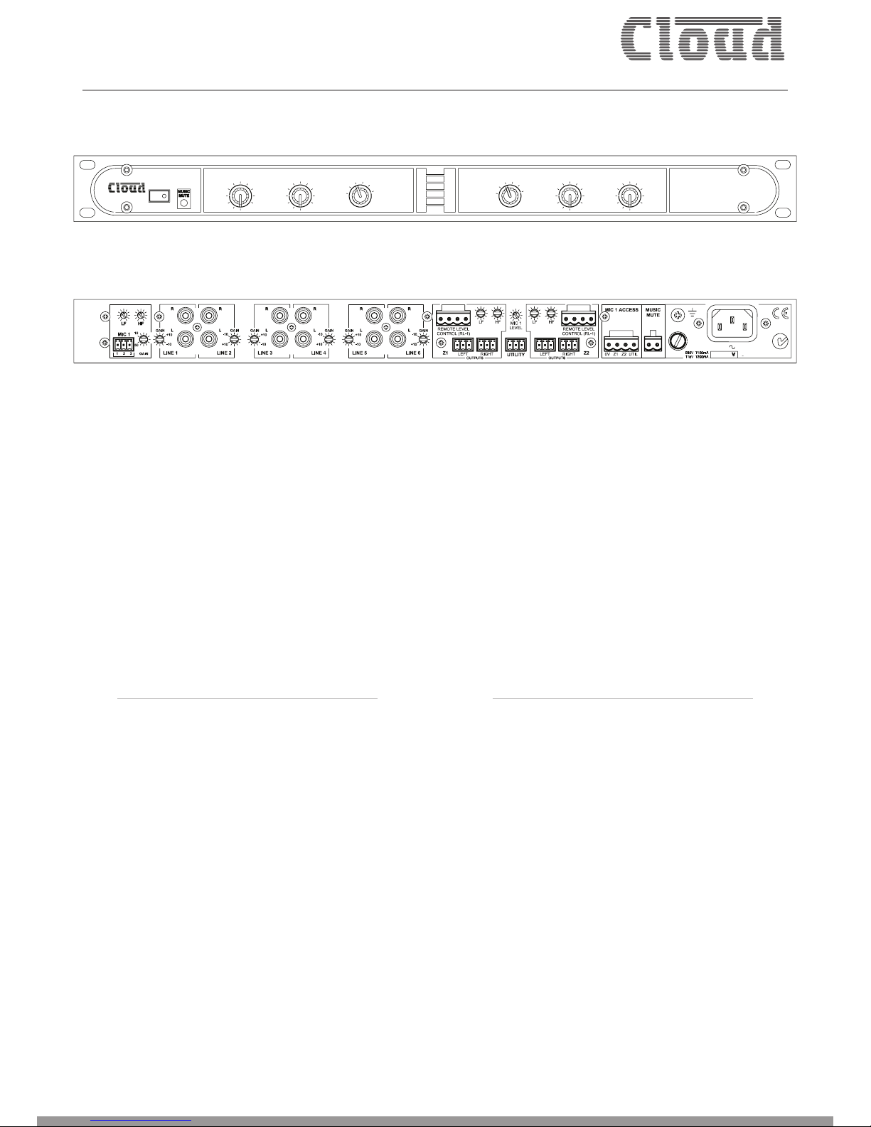
The Cloud CX163 is a two-zone, rack-mounting (1U) audio mixer
suitable for use in licensed premises or other leisure sector venues,
shops, ofces, hotels, or any space where easy control of background
music in two separate areas needs to be combined with a microphone
or paging system.
The CX163 has six stereo line inputs and a microphone input. It has
two separate zone outputs, in each of which one of the line inputs
and the microphone input may be mixed together. Separate control
of music source selection, and music and mic levels are provided for
each zone. The main outputs are stereo, and there is an additional
xed-level mono utility output, which is suitable for speakers in
general areas such as foyers and toilets. Music level may be controlled
remotely in each zone by standard Cloud RL-1 remote control panels
if wished, and if zone outputs are congured as mono, separate RL-1s
may be connected to control the left and right outputs.
The mixer may be congured to suit most paging systems: the mic
input may be routed to either zone by short-to-ground access
connections. For Zone 1 only, LINE 6 input may be set to have
priority over any other selected to facilitate connection of a digital
sound store or similar device.
Bose® EQ cards may be tted to any or all of the three outputs.
• Provides music and paging in two zones
• Front panel controls for music source, music level and mic level
in each zone
• Six (unbalanced) stereo line inputs with individual gain controls
• Balanced mic input – 15 V phantom power available
• Sensitivity and HF/LF EQ adjustment for mic input
• Two electronically-balanced stereo zone outputs (congurable
mono by internal jumpers), each with HF/LF EQ adjustment
• Additional electronically-balanced mono utility output with
independent mic level adjustment
• Utility output source selection (via internal jumper) – follows
either Zone or always LINE 1
• Paging priority control via short-to-ground access connector
• Selectable music-under-microphone ducking
• Zone 1 has selectable LINE 6 priority with choice of release
times
• Music Mute control input (NO or NC) for interface to
emergency system
• Compatible with standard Cloud RL-1 remote music level
control panels
• Optional Bose® EQ cards available
• 1U 19” rack mounting unit
Cloud CX163 Zone Mixer - rear panel view
Cloud CX163 Zone Mixer - front panel view
POWER 40-60Hz
10%
FUSE
RATING
N123
+
POWER
CX163
ZONE 1 ZONE 2
MICROPHONE LEVEL MUSIC LEVEL MUSIC LEVEL MICROPHONE LEVEL
MUSIC
SOURCE
MUSIC
SOURCE
11
22
33
44
55
66
1
2
34
5
6
1
2
34
5
6
2 ZONE
STEREO AUDIO
MIXER
Clearly better sound
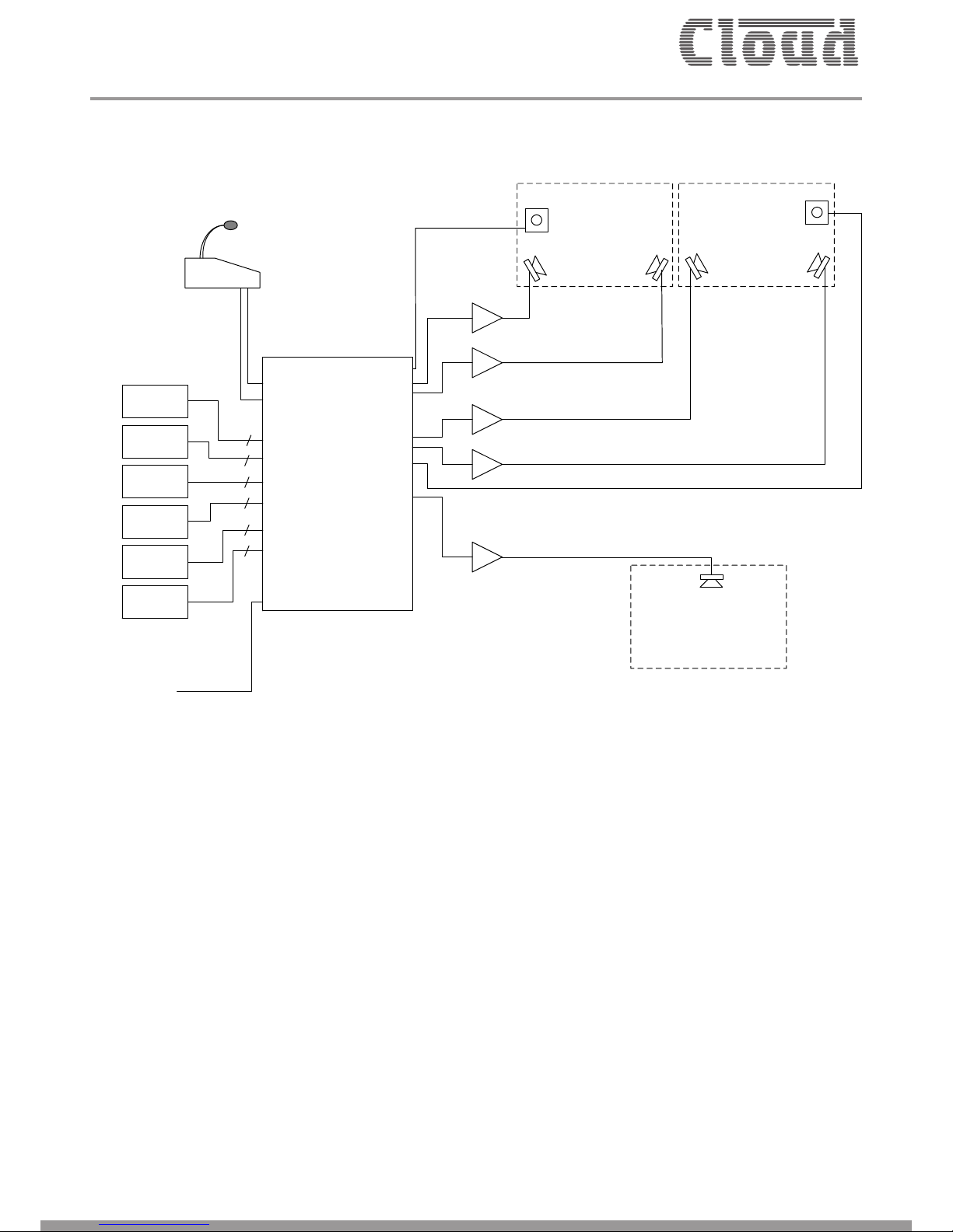
System Example
The example shows a CX163 used to provide music and paging in
two separate areas (zones) of a pub or bar. Each area can set its own
volume by means of the local RL-1 remote control panels (optional).
Alternatively, it can be set from the front panel of the mixer itself.
Music at a lower level could be made available to a third area, such
as the lobby or toilets.
Paging to either or both zones is achieved using a paging mic (such as
the Cloud PM4), which would typically be located somewhere other
than either of the two zones.
Note that the jukebox is shown connected to Line input 6; If Line 6
Priority is enabled in the mixer, then whenever the jukebox is in use it
will always be heard in Zone 1, regardless of the music source setting.
MIC IN
LINE 1
LINE 2
LINE 3
LINE 4
LINE 5
LINE 6
ZONE 1
ZONE 2
UTILITY OUT
L
R
L
R
REMOTE
REMOTE
ACCESS
MUSIC MUTE
GENERAL AREA
ZONE 1 ZONE 2
AMPLIFIERS
CD
PLAYER
MUSIC
SERVER
DTV BOX
SAT BOX
JUKEBOX
iPOD
DOCK
FROM FIRE
CONTROL PANEL
PAGING MIC
MUSIC SOURCES
(all stereo)
2
2
2
2
2
2
RL-1 RL-1

Clearly better sound
Technical Specications
Line Inputs
Frequency Response 20 Hz-22 kHz, 0 -0.5 dB
Distortion 20 Hz-22 kHz, <0.05% Typical
Sensitivity 100 mV (-17.8 dBu) to 1.5 V (+6 dBu)
Input Gain Control 24 dB range
Input Impedance 48 kΩ
Headroom >20 dB
Noise 20 Hz-22 kHz (0 dB gain), <-84 dBu rms typical
Equalisation LF: ±10 dB @ 50 Hz, HF: ±10 dB @ 10kHz
Microphone Input
Frequency Response 100 Hz -3 dB (lter), 20 kHz <-0.5 dB
Distortion <0.05%, 20 Hz – 22 kHz typical
Gain Range 10 dB to 50 dB
Input Impedance >2 kΩ (balanced)
Common Mode Rejection 1 kHz >70 dB
Headroom >20 dB
Noise 20 Hz -22 kHz (150Ω), -128 dB EIN
Equalisation LF: ±10 dB @ 100 Hz, HF: ±10 dB @ 5 kHz
Outputs
Output 0 dBu (775 mV) via 3.5mm-pitch plug-in screw terminals
Minimum load impedance 1.2 kΩ
Maximum output level +20 dBu
General
Power Input 230 V/115 V ±10%
Fuse Rating T100 mA 230 V, T200 mA 115 V
Fuse Type 20 mm x 5 mm 250 V
Dimensions 482.6 mm x 44 mm (1U) x 152.5 mm
Weight 2.15 kg
Clearly better sound
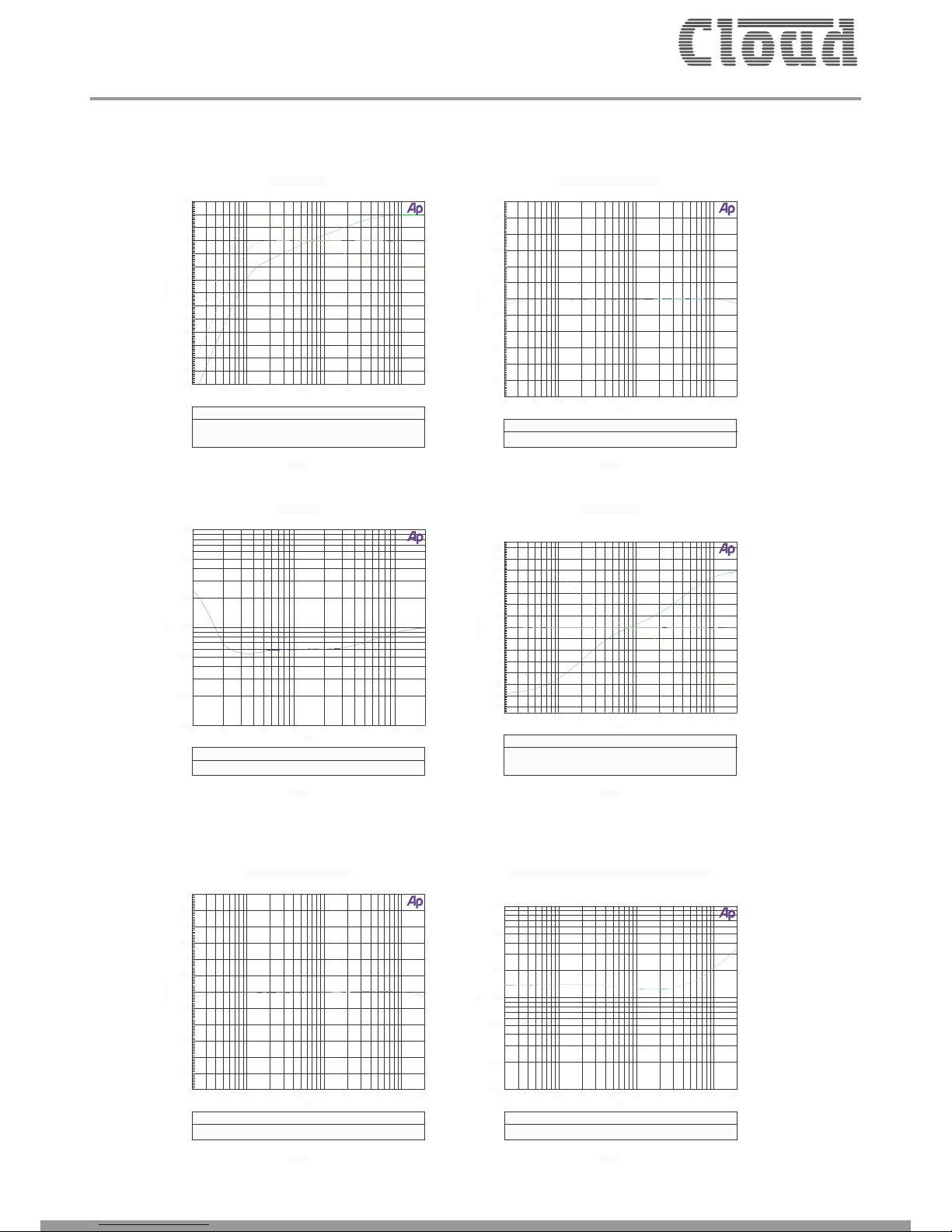
Graphs
Mic EQ Curves
Last.at1
ColorSweep Trace Line Style Thick Data Axis Comment
1 1 Cyan Solid 1Anlr.Ampl Left
2 1 Green Solid 1Anlr.Ampl Left
3 1 Yellow Solid 1Anlr.Ampl Left
-55
+15
-50
-45
-40
-35
-30
-25
-20
-15
-10
-5
+0
+5
+10
d
B
r
20 20k50 100 200 500 1k 2k 5k 10k
Hz
Music eq curves
Last.at1
ColorSweep Trace Line Style Thick Data Axis Comment
1 1 Cyan Solid 1Anlr.Ampl Left
2 1 Green Solid 1Anlr.Ampl Left
3 1 Yellow Solid 1Anlr.Ampl Left
-14
+14
-12
-10
-8
-6
-4
-2
-0
+2
+4
+6
+8
+10
+12
d
B
u
20 20k50 100 200 500 1k 2k 5k 10k
Hz
Music Frequency Response
Last.at1
ColorSweep Trace Line Style Thick Data Axis Comment
1 1 Cyan Solid 1Anlr.Ampl Left
-3
+3
-2.5
-2
-1.5
-1
-0.5
-0
+0.5
+1
+1.5
+2
+2.5
d
B
u
20 20k50 100 200 500 1k 2k 5k 10k
Hz
Music Frequency Response
Last.at1
ColorSweep Trace Line Style Thick Data Axis Comment
1 1 Cyan Solid 1Anlr.Ampl Left
-3
+3
-2.5
-2
-1.5
-1
-0.5
-0
+0.5
+1
+1.5
+2
+2.5
d
B
u
20 20k50 100 200 500 1k 2k 5k 10k
Hz
Mic THD+N
Last.at1
ColorSweep Trace Line Style Thick Data Axis Comment
1 1 Blue Solid 1Anlr.THD+N Ratio Left
0.001
0.1
0.002
0.005
0.01
0.02
0.05
%
100 20k200 500 1k 2k 5k 10k
Hz
Music THD+N 0dBu Signal Measured over 80kHz BW
Last.at1
ColorSweep Trace Line Style Thick Data Axis Comment
1 1 Cyan Solid 1Anlr.THD+N Ratio Left
0.001
0.1
0.002
0.005
0.01
0.02
0.05
%
20 20k50 100 200 500 1k 2k 5k 10k
Hz

Clearly better sound
Block Diagram
L
R
1
1
1
2
2
2
3
3
3
EQ
PHANTOM
GATE
GATE
PRIORITY
PRIORITY
RELEASE
TIME
PRIORITY
EQGATE
GATE
VCA
SPEAKER
MODULE
SPEAKER
MODULE
OPTIONAL
REMOTE
(RL-1)
MUSIC
MUTE
GAIN
100Hz
+
+
GAIN
UTIL
OUTPUT
(0dBu)
FROM
RIGHT
CHANNEL
STEREO
MONO NRM
DEF
J8(Z1)
ACC
ACC
AVO
AVO
OFF ON 3s 6s
OFF
ON
J13(Z1)
J9 J10
J5
J14(Z1)
J6
J15

Clearly better sound
E&OEIssue_1.0
The mixer shall be equipped with six unbalanced stereo music inputs
on rear panel phono sockets (RCA jacks), one electronically balanced
microphone input, two main zone (L & R) electronically balanced
outputs and one electronically balanced mono utility output, all on
rear panel multipin connectors.
The mixer shall have two stereo channels designated Zone 1 and
Zone 2. Except where indicated below, the channels shall be identical.
The microphone input shall be mixed and summed with the music
input selected in each channel separately. Each channel shall have
its own front panel microphone level control. The music input to
each channel shall be selected by 6-position front panel rotary
switches. It shall be possible to control the level of the music source
independently of the microphone levels in each channel.
Each music input and the microphone input shall also have a rear
panel input sensitivity control. Independent 2-band equalisation
adjustment shall be provided on the rear panel for i) the music
signal in each mixer channel and ii) the microphone input. Phantom
power shall be available at the microphone input when selected by
an internal jumper.
A control input shall be provided to activate the microphone input
by external contact closure, with separate routing to each mixer
channel. It shall be possible to congure the mixer such that this
function is overridden and the microphone input is always active.
It shall also be possible to congure the mixer to perform the
following functions: i) detection of a signal on the microphone input
will automatically reduce the music level by 30 dB, ii) one line input
will automatically override all others when a signal is present in
Channel 1, even if unselected.
Optional remote control panels shall be available to permit control
of music level in either mixer channel; it shall be possible to retrot
these to the mixer at any time. The remote control panels shall
connect via a rear panel multipin connector. It shall be possible to
disable the front panel music level controls by moving an internal
jumper. An external control input shall be provided to allow muting of
the music source by a re alarm or other external emergency system
via isolated, ‘volt-free’ contacts, and this input shall be congurable to
respond to either a short or open external circuit.
The mono utility output shall be congurable internally to i) follow
whichever music source is selected to either mixer channel, or ii)
to be permanently fed with a mono sum of one line input; this line
input will not be the same one that can be set to have priority over
the other line inputs. If the utility output is selected to follow the
music signal in ,mixer channel 1, and the priority line input feature is
enabled, the priority line input will also feed the utility output when
the input becomes active. The microphone input shall also be mixed
into the utility output and it shall be possible to set the microphone
level at the utility output independently of that at the main outputs
with a rear panel control.
The mixer shall accept internal Bose® Series IIS plug-in equaliser
cards to permit use with compatible Bose® loudspeakers. It shall be
possible to t these in any or all of the main or utility outputs.
The mixer shall be built in a 1U steel chassis for mounting in a
standard 19” rack. The mixer will be tted with a front-panel
power switch with LED indication. Two mains supply variants shall
be available: 230 V or 115 V. Mains supply shall be connected via a
detachable IEC cable.
The mixer shall be the Cloud CX163; the optional remote control
panel shall be the Cloud RL-1.
Architect’s and Engineer’s Specication
Other manuals for CX163
2
Table of contents
Other Cloud Music Mixer manuals

Cloud
Cloud CX163 User manual

Cloud
Cloud CXM User manual

Cloud
Cloud CX261 User manual

Cloud
Cloud CX163 User manual

Cloud
Cloud LM-2 Series User manual

Cloud
Cloud CXM Operation manual

Cloud
Cloud Z4II Operation manual

Cloud
Cloud Z4MK4 Operating and maintenance instructions

Cloud
Cloud Matrix 4 Operation manual

Cloud
Cloud CX242 Operation manual


