Overview
The Sirius 500 is a 512 channel, and
the Sirius 250 is a 256 channel lighting
desk, incorporating many of the
flexible, friendly and robust features of
the original Sirius 24 and 48 models,
but also introducing new techniques
and the latest technology.
The traditional Sirius hallmarks are all
there: Key Switch for changing
between operating modes, two
Presets, Submasters, GO button,
Memory Effects, etc., together with
new features, such as two built-in liquid
crystal displays for operator feedback,
an optional external monitor, external
keyboard and mouse, 4 Wheel Drive
®
for easy control of fixture parameters,
floppy disk backup, and much much
more.
The Sirius 500 & 250 can control all
types of fixture: a single channel fixture
(often referred to as a generic or
conventional), consisting solely of a
lamp; a multichannel fixture, such as a
generic with either a colour scroller or a
gobo rotator; or an intelligent
multichannel fixture, which covers
many types of fixture, such as a
moving mirror fixture (Cyberlight) or a
moving yoke fixture (VL5).
The Sirius 500 & 250 use two types of
control channels to regulate fixtures.
Firstly, Brightness channels control
lamps or dimmers, by means of the
channel Preset faders. The green
output lights on the desk mimic the
DMX Brightness output for that fixture.
/p1-3/3
The second type of channel controls all
non-Brightness attributes (i.e. Colour,
Beamshape, and Position) of
multichannel fixtures, using 4 Wheel
Drive
®
. This makes programming even
the most complex multichannel fixtures
simple and fast. The fixture may have
more than one channel controlling
Colour, Beamshape or Position
attributes. For example, the Colour
attribute could comprise four separate
channels - one each for cyan,
magenta, yellow and a colour wheel.
The Beamshape attribute could have a
gobo wheel, an iris and a shutter. The
individual channels comprising a
Colour, Beamshape or Position
attribute are referred to as parameters.
All fixtures must have a Brightness
channel, which is controlled by the
channel Preset faders. The Desk uses
the Brightness channel numbers as
fixture numbers. Thus the flash buttons
below the Preset faders have two
functions; they can be used both to
flash the Brightness channel, and also
to select fixtures for programming
non-Brightness attributes.
Brightness, Colour, Beamshape and
Position memories are stored in four
separate areas, one for each attribute.
A single memory can record
information about one particular
attribute for all fixtures connected to
the desk.
The desk operating system handles
Brightness and non-Brightness
memories in different ways. Brightness
memories are mixed on the DMX
output on a Highest Takes Precedence
(HTP) basis. This is the traditional way
Two Preset desks mix their outputs to
be interpreted by dimmers. The highest
(or brightest) value is the most
important, and controls the channel. In
HTP a channel value of zero turns the
dimmer off.
Non-Brightness memories are mixed
on the DMX channel on a Latest Takes
Precedence (LTP) basis. This means
that the latest value on a channel is the
most important and controls the
parameters action. In contrast to HTP,
zero is NOT off in LTP, as it is not
possible, for example, to turn a mirror
to an off position. In HTP the highest
(or brightest) value is the most
important, but in LTP all values have
the same importance. Although the
desk manages this for the operator, it
is nevertheless important to
understand this distinction when
running a show.
WARNING
Maintenance
A dimmer or fixture must always be isolated
from the mains supply before proceeding
with any maintenance, even if the channel is
set to zero.
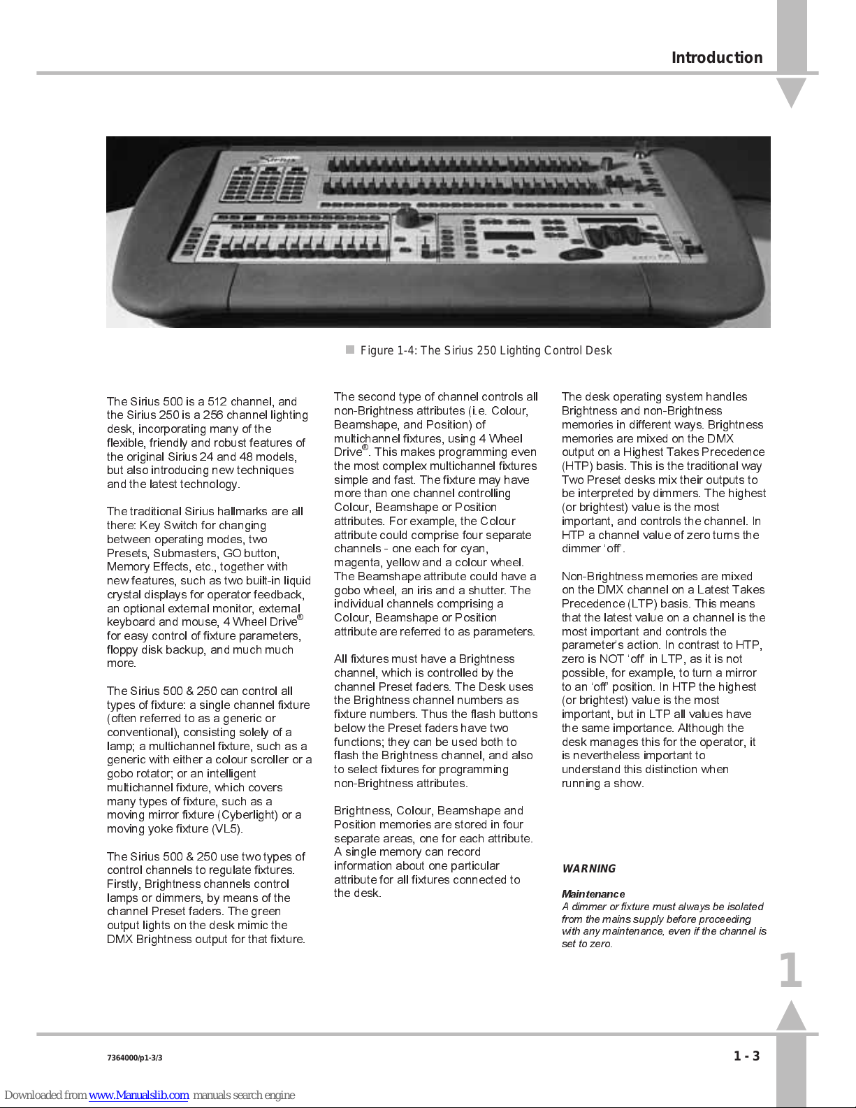
n
Figure 1-4: The Sirius 250 Lighting Control Desk
1
Introduction
7364000/p1-3/3 1 - 3