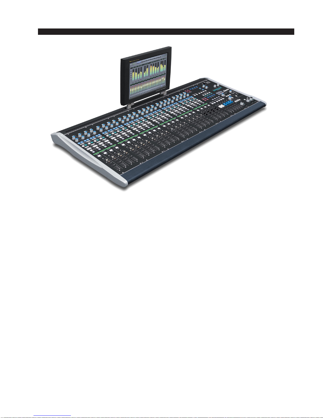
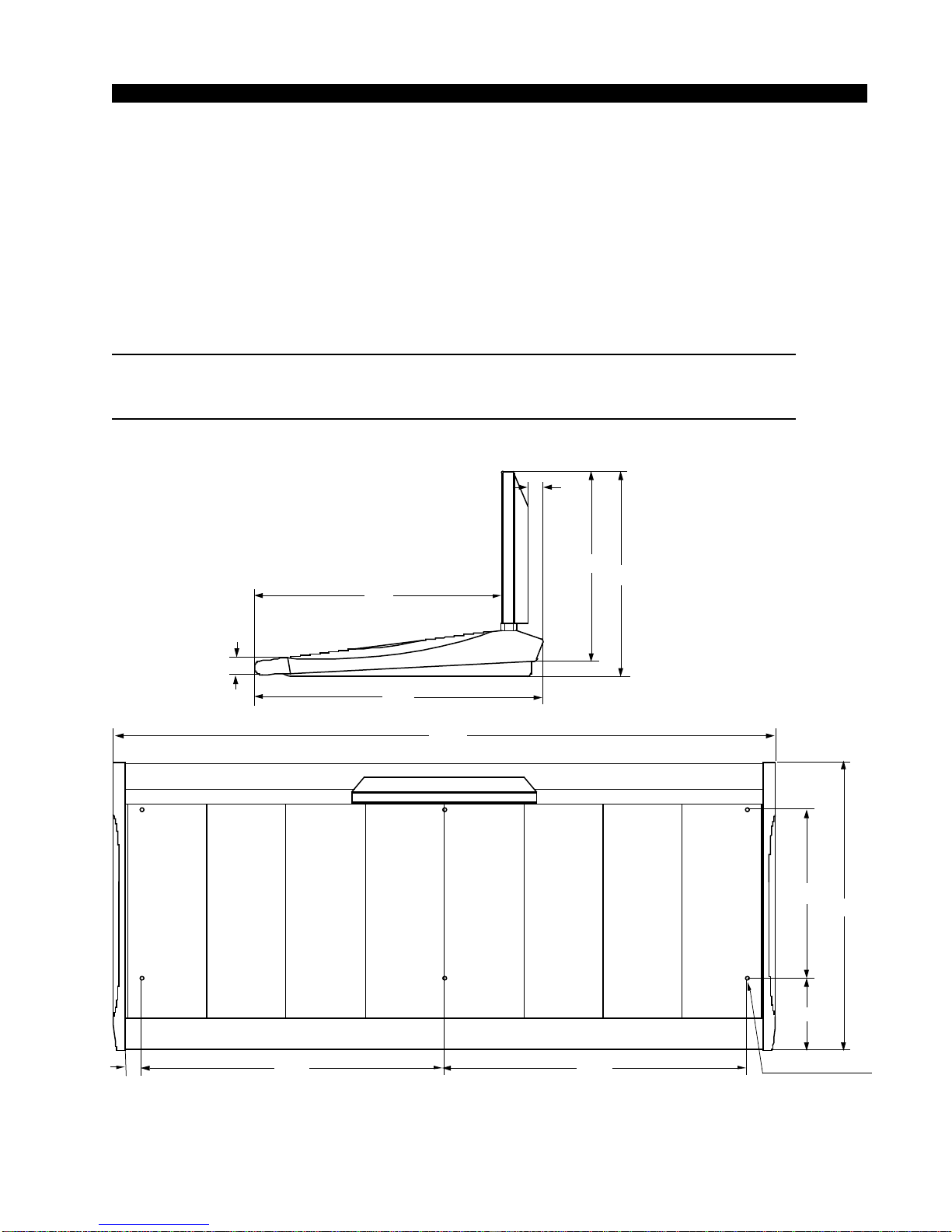
INPUT PANEL
page 5
D-8 / Feb 2009
panel), the available inputs are displayed in the
fader’s 8-character SOURCE display. When
the desired input source is scrolled into the
SOURCE window, pressing the TAKE button
(on the MON-D8 panel) will cause that source
to be switched to the input of the channel, and
the source name will be displayed in the
SOURCE window.
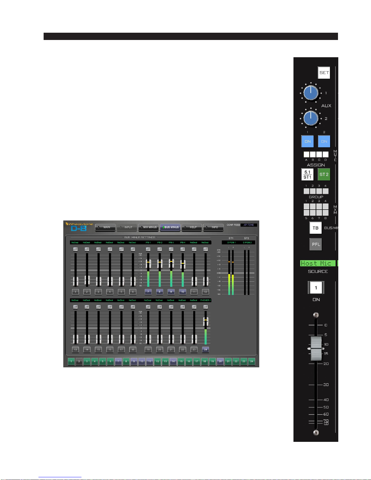
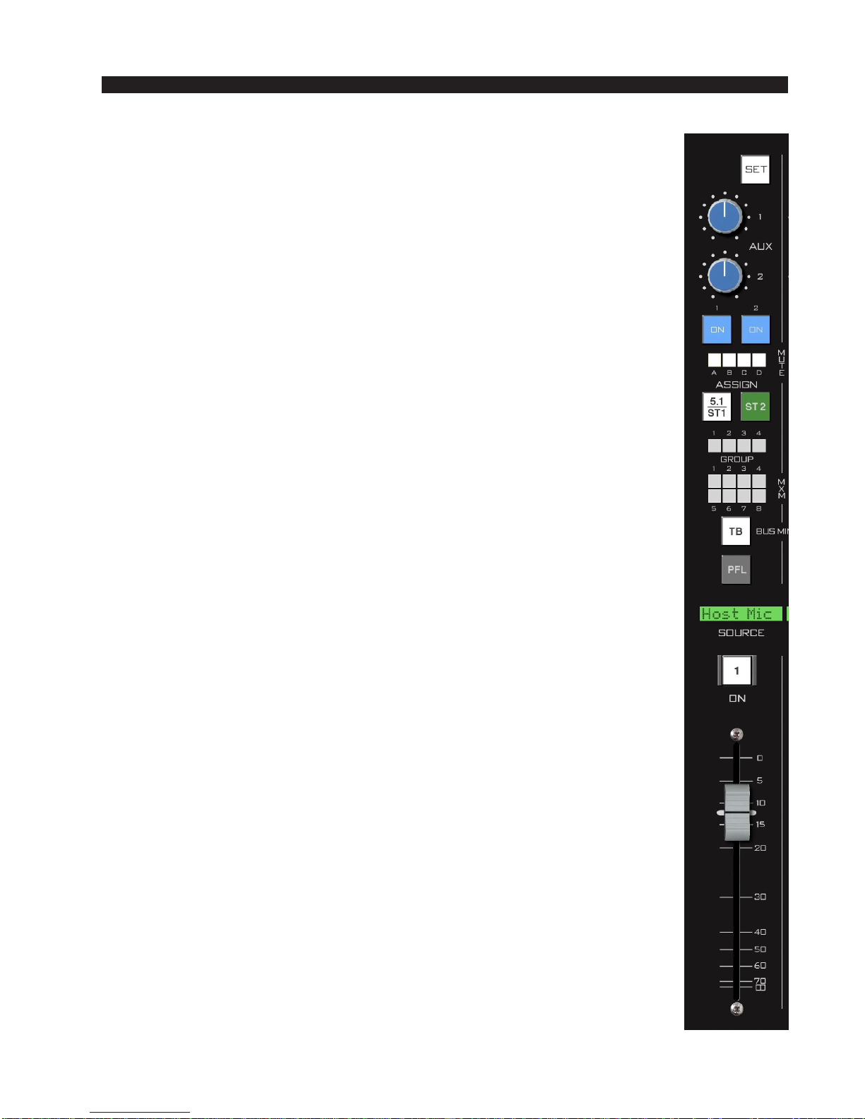
SET Button
TheSETbuttonislocatedatthetopofeachfaderstripandforcesthefocus
oftheVGAtotheselectedinputfaderstrip.Thisallowstheoperatortoaccess
various controls and displays in the MON-D8 panel and apply them to the
selectedchannel. To use, press theSET buttonand then make your appropri-
ate section settings in other areas of the control surface. Once a SET button
hasbeenpressed,thebuttonlightsup,andallsettingchangeswillapplytothat
inputchanneluntiladifferentinputSETbuttonispressed.TheSETfunction
may be configured in the Options.txt file (see Appendix 1) to automatically
timeout after 20 seconds.
AUX
Each channel of the input panel has two AUX send knobs (AUX 1 and
AUX 2) to set the level of the channel’s audio in the AUX SENDS. Two
switches (ON 1 and ON 2), determine whether the channel feeds AUX 1
(ON 1) and/or AUX 2 (ON 2). Aux sends may be pre-configured in the
Options.txt file to be tapped pre or post fader. See the User Programming
section in the Appendix 2 of this manual for details.
MuteAssign Displays
EachfadercanbeassignedinanycombinationtoMUTEMASTERA,B,
C,or Dbypressing thefader’s SETbutton,then selectingthe desired INPUT
CHANNEL MUTE ASSIGN switch located at the top of the MASTER fader
panel.TheMUTEindicatorLED’sonthefaderstripwilllightsolidtoindicate
theassignmentandflashslowly when muted.Anychannelthatisassigned to
aMUTEMASTERwillbemutedwhenthecorrespondingMUTEMASTER
is activated. Mute masters are useful for turning several microphone faders
Off with a single button press - like when going to a break.
ASSIGN Switches - 5.1/ST 1 and ST 2
ASSIGN buttons assign the input channel signal to the two main buses:
5.1 (surround)/ST 1 (stereo 1) and ST 2 (stereo 2), respectively. The buttons
lightuptoshowwhichbusestheinputchannelhasbeenassignedto.Notethat
the5.1/ST 1switchroutestothefirstmasterbus.Thismasterbushasbeenpre-
configured to be a surround bus or stereo bus; it is not two separate buses.
MON-D8 Panel