Clyde CKRS 05 User manual

November 2014
Engineering Data Sheet 801/3
CKRS
Assembled cast iron boiler
Natural gas
Propane Gas
Class D oil
Dual fuel
75 kW
to
145 kW
Contents Page
General information 2
Dimensions & data 3
Installation requirements 4 & 5
Boiler control & wiring 6 & 7
Seasonal efficiency of over 84% gives compliance with ADL2B 2013 for gas
fired boilers without the need for additional heating credits
Compact heat exchanger gives small footprint relative to output
Delivered as a ready-assembled block or can be site assembled for easy
access if preferred
Wide range of 2-stage gas and oil burners available

Materials & boiler assembling
The boiler is supplied as standard with the cast iron
sections assembled. The boiler blocks can be split and
reassembled at site to special order. Each section is tested
hydraulically for soundness in accordance with EN303.
The insulation and steel jacket is already fitted to the boiler.
The boiler control panel and burner are packed separately
for fitting on site.
Site assembling should only be undertaken by Carnot or
their authorised engineer. All insulating and refractory
materials are included, with ceramic sealing ropes for all
access doors.
Handling
Offloading, dry storing and placing of equipment in the
boiler room is the responsibility of the installer.
Equipment must be dry stored and protected from frost.
Cartons must not be crushed or otherwise damaged.
Commissioning
Carnot undertake commissioning of boilers.
General information
Description
CKRS cast iron sectional boilers are designed for use in either open vented or pressurised heating systems up to 6 bar
working pressure with gas, oil or dual fuel burners. There are five models in the range 75 kW to 145 kW. The boiler has a
pressurised combustion chamber and matched burners offered are all capable of overcoming the boiler resistance without
the assistance of the chimney.
These are 3-pass boilers and comply with the efficiency requirements of ADL2: 2013 of The Building Regulations.
Application
CKRS boilers are made from Grade GG20 cast iron and conform with the requirements of EN 303. The boilers are
suitable for use in LTHW heating systems with a maximum operating pressure of 6 bar and maximum temperature of
90oC.
CKRS boilers may be fired by Natural gas, LPG, Class D or Class C oil with 1 or 2-stage control.
The boiler is suitable for use in either open vented or pressurised heating systems. It is not suitable for use as a direct
water heater. Where potable water is required, a matching calorifier or plate heat exchanger must be provided in the
system.
Statutory requirements
CKRS boilers are CE marked and must be fired by a compatible burner certified to EN267 (oil firing) or EN676 (gas firing)
tocomplywiththeBoiler(Efficiency)Directive 1993.
The installation, assembling and commissioning of the boiler must be carried out by a qualified engineer in accordance
with the instructions provided.
Gas supplies and gas burners must be installed and commissioned by a qualified person, eg. a Gas Safe registered
engineer.
Commissioning charges do not include servicing during the
guarantee period. This may be carried out under service
contract or to specific order.
Boiler log book
A permanent record of commissioning and servicing data
and measurements should be kept in the building log book.
It should be kept safe and updated whenever routine or
emergency work is performed on the boiler.
Guarantee
Subject to correct handling, installation and operation, all
equipment is guaranteed for twelve months from the date
of despatch. Boiler sections are guaranteed for a period of
five years from the date of despatch.
The guarantee is not valid if the boiler is subjected to
thermal stress, becomes blocked with debris and/or
carbonate deposits from the system water and/or there is
no documented evidence of commissioning by a
competent engineer.
Fig 1 3-pass operation of boiler
FLOW
RETURN
Second pass
Third pass
EDS801/3 page2

Dimensions and technical data
550
820
690
544
65
280
L
HO
HI
EDS801/3 page3
Dimensions
Boiler model CKRS 05 CKRS 06 CKRS 07 CKRS 08 CKRS 09
Output kW 75 93 110 127 145
No. sections 5 6 7 8 9
Overall length L mm 800 922 1044 1166 1288
Combustion chamber length mm 550 670 790 910 1030
Combustion chamber diameter mm
Boiler door thickness mm
Boiler flow connection HO
Boiler return connection HI
Flue spigot diameter mm
Technical data
Nominal heat output (full load) ncv kW 75.6 93 110.5 127.9 145.3
Nominal heat input (f ull load) ncv kW 81.6 100.5 119.3 138.1 157
Efficiency at 100% load (ncv) % 92.6 92.5 92.6 92.6 92.5
Efficiency at 30% load (ncv) % 95.3 95.4 95.4 95.5 95.6
Boiler seasonal efficiency(1) % 85.4 85.4 85.4 85.5 85.6
Natural gas consumption (gcv) m³/h 8.4 10.4 12.4 14.3 16.3
Oil consumption class D (ncv) kg/h 6.9 8.5 10.1 11.6 13.2
Dry w eight (excludes burner) kg 289 334 381 429 474
Water volume litres 55 65 75 85 95
Flue gas mass flow @3% oxygen m³/h 8.4 10.4 12.3 14.2 16.2
Chimney draught Pa
Gas side resistance mbar 1.65 1.82 2.05 2.3 2.55
Flue gas temperature rise @3% oxygen Nat gas (2) °C 166 162 159 157 154
Class D oil °C 188 181 178 176 173
Maximum w orking temperature °C
Maximum hydraulic w orking pressure bar
CE-Registration number
Water flow rates and hydraulic resistances
Water flow rate at 11°C temp. rise l/s 1.64 2 2.39 2.77 3.15
Hydraulic resistance at 11°C temp. rise kPa 2.52 3.1 4.45 5.5 7.27
Water flow rate at 20°C temp. rise l/s 0.9 1.11 1.32 1.52 1.73
Hydraulic resistance at 20°C temp. rise kPa 0.76 1 1.56 1.9 2.23
Water flow rate at 30°C temp. rise l/s 0.6 0.74 0.88 1.02 1.15
Hydraulic resistance at 30°C temp. rise kPa 0.38 0.54 0.74 0.9 1.13
Notes: (1) Calculated from the non-domestic heating and cooling compliance guide for conformance w ith
ADL2A and ADL2B 2013 using the formula n
seasonal
=
0.81n
30%
+ 0.19n
100%
(2) BS 7190:1989
336
102
R2
R2
150 180
6
CE 1015BR0260
5
90

Installation requirements
Boiler location (Refer Figs 2 & 3)
The location chosen for the boiler(s) must be frost free,
provide for a satisfactory flue system and an adequate air
supply for combustion and ventilation. Adequate access is
necessary for boiler and burner servicing.
Boilers must not be installed in areas where flammable
vapours are likely to be present. To avoid damage to the
boilers, contamination of the combustion air by high levels
of dust or halogenated hydrocarbons (eg. Solvents, spray
can propellants, cleaning agents, adhesives, etc) must be
avoided.
Boilers should be installed on a plinth which is at least
50mm high and is smooth and level (NB : for some burners
with acoustic shrouds the plinth may need to be higher -
refer Sales Office).
An uneven plinth can inhibit freedom for expansion and
contraction of the boiler during operation.
Burners
Boilers can be supplied with one or two stage Natural gas,
LPG, Class D or Class C oil burners. A choice of burner
makes is available.
•
•
•
•
•
•
•
•
•
W3
AA
W2
W1
W4
Boiler
•
Fig 2 - Wall clearances
Plant room layout (Refer Fig 2)
When planning the layout of the boiler room, allowance
must be made for opening the boiler door, boiler
assembling, boiler cleaning and maintenance. The boiler
door may be hinged from the right (as illustrated) or the left.
A ceiling height of at least 2.3m is recommended. Wall
clearances are:
W1 - at least 700mm.
W2 - burner length A + 100mm.
W3 - 1000mm (in front of boiler for cleaning).
W4 - 500mm minimum (behind boiler for cleaning).
Plinth dimensions (Refer Fig 3)
Plinth height - at least 50mm, smooth and level.
Fig 3 - Plinth dimensions
Fuel specification
Natural gas (GCV 38.76 MJ/m3) with a minimum gas inlet
pressure according to the burner model specified.
BS2869 Class D oil (35 sec). Advice should be sought
from the oil supplier regarding the storage of Class D oil.
Fuel supply pipework
Install gas or oil supply pipe(s) and service valve(s) so as
to allow free access to the boiler and full opening of the
furnace door without removing the burner from the boiler
door (see below).
Commissioning of the gas supply pipework and
components must be carried out by a qualified person, eg,
a Gas Safe registered engineer. The gas meter and
supply must be sited in accordance with the requirements
of BS6400.
Boiler L1 mm
CKRS-05 880
CKRS-06 915
CKRS-07 1125
CKRS-08 1245
CKRS-09 1370
L1
650
min
EDS801/3 page4

Installation requirements
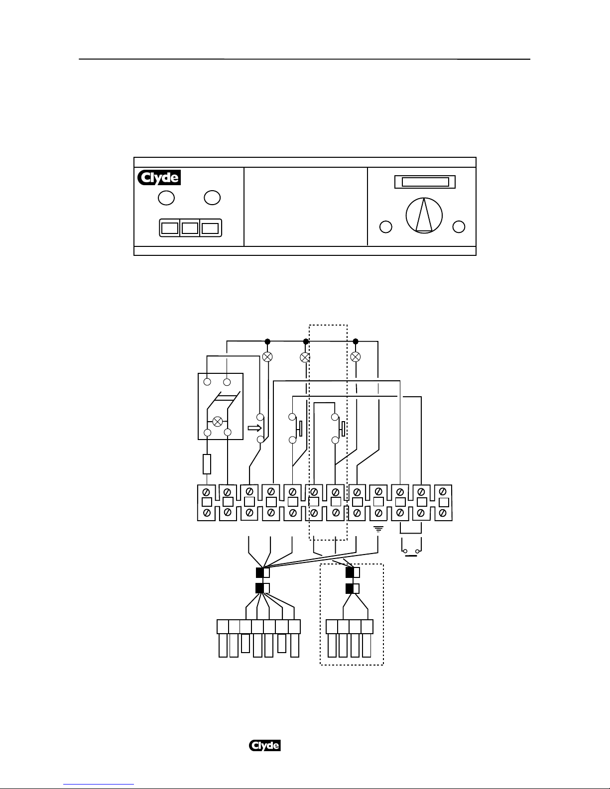
Fig 5 - Electricity supply
Electrical supply (Refer Fig 5)
230Vac 1ph burners are supplied as standard. The fused
supply should be taken to the control panel only. The
harness and connector supplied will feed the burner.
The electricity supplies to the burner and boiler control
panel must be wired in accordance with IEE Regulations. A
separate supply and isolating switch is required for each
boiler in the plant room.
All isolating switches and fuses must be provided by the
installer. Burner start/run currents for fuse specification are
available on request. Burner wiring diagrams and technical
data are also available on request.
All connections between the boiler control panel and the
burner are made through harnesses with matching plugs
and sockets, supplied as standard.
Note: Fig 5 is only diagrammatic. Double pole switches with
the required minimum separation must always be used.
Air supply
Air for ventilation and combustion must be provided for
gas fired boilers in accordance with either BS
6644:2011 or IGE/UP/10. Air supply for oil fired boilers
must conform to BS 5410 : Part 2.
Chimney design
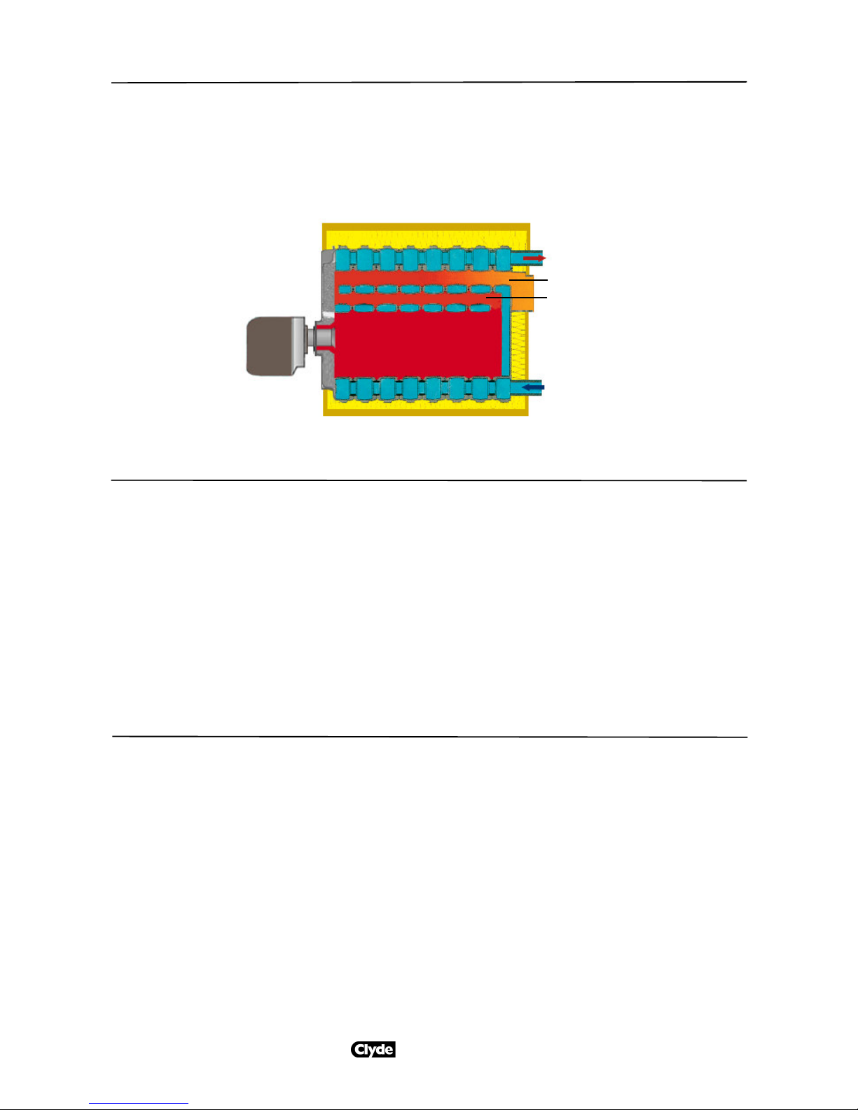
The CKRS boiler is designed to operate with a
pressurised combustion chamber and the chimney is
not required to assist the burner in overcoming the
boiler resistance. The chimney must cater for the total
internal resistance of the flue system from each boiler
outlet and not impose an additional load on the
burner.
Water circulation (Refer Fig 4)
The flow water temperature from the boiler must reach
60°C (gas firing) or 50°C (oil firing) within 10 minutes
of the boiler being brought into operation. Thereafter,
water circulation should be maintained through the
boiler such that the boiler flow water temperature is
always above 60°C (gas firing) or 50°C (oil firing). A
pump overrun facility is necessary to ensure that
water circulation is maintained for at least three
minutes after the boiler is switched off.
There are several ways of providing boiler protection,
eg shunt pumps, primary loops, etc. A typical boiler
pump and 3-port valve arrangement is shown in Fig
4a and b.
For multi-boiler systems a ‘reverse return’ pipework
configuration is required to ensure equal distribution
of water flow through the boilers.
Water treatment
Whenever a new boiler is connected to an existing
system, the pipework must be thoroughly cleaned and
flushed. Carnot recommend that a permanent means
of filtration be fitted into the return pipework, such as a
sludge trap, hydrocyclone or full flow duplex filters.
The boiler guarantee will be invalid if waterways are
blocked by debris or carbonate deposits. Long term
water treatment is essential to the economic operation
and life of both new and refurbished heating systems.
For full information on cleaning, flushing and
protecting hot water systems, refer to BSRIA
Application Guide AG 1/2001.
T
T
T
Fig 4a Multiple boilers with individual pumps
Fig 4b Alternative arrangement for boiler protection with a primary
loop
•
•
•
•
•
Boiler
Burner
loom
Isolator
& fuse
L
Control
panel
Burner
N
E
Single
phase
motor
EDS801/3 page5

Boiler control panel and wiring
Control panel CKCR2 provides 2-stage burner control for high/low operation whilst panel CKCR1 provides 1-stage
burner control for on/off, modulating or LFS operation. Thermostat TR is a 1-stage item with CKCR1 and a dual
thermostat (1 and 2 stage) with CKCR2.
0/I L1 L2
Fuse STB
L3 L4
TR
Thermometer
EDS801/3 page6
Fig 6 Boiler control panel
¬
1234 5 678910 11 12
L1 T1
à
à
EC1 (removable link)
T2 T8
T6
STB TR TR2
Fuse
L1
L2 L3 L4
L N N
L1
N
T1T2
S3
B4 ET8T7
B5 T6
CKCR2 only
CKCR2 only
Burner loom stage 1 Burner loom stage 2
Fig 7 Boiler control panel wiring

EDS801/3 page7
Boiler control panel and wiring
Key to figs 6 and 7
EC1 External Energy Control 1(eg timeclock)
L1 On/off indicator lamp
L2 Boiler high limit lock-out lamp (lamp is illuminated when
running and goes out in lock-out condition)
L3 Stage 1 run lamp
L4 Stage 2 run lamp
STB High limit thermostat (factory set)
TR Boiler thermostat (1-stage for CKCR1 or dual operation [TR
and TR2] for CKCR2)

5 Burgesshall Drive
Maidstone
Kent ME17 1SH
t : 01622862746
w : carnotconsult.com EDS 803/2
November 2014
Carnot Consult Ltd
This publication is issued subject to alteration or withdrawal without notice. The illustrations and specifications are not binding in
detail. All offers and sales are subject to the Company's current terms and conditions of sale, a copy of which is available on request.
This manual suits for next models
5
Table of contents
Other Clyde Boiler manuals
Popular Boiler manuals by other brands

Sime
Sime RX 26 BF manual

Viessmann
Viessmann KRT 150 series Service manual

Stropuva
Stropuva S7 Technical passport installation and maintenance instructions

Weil-McLain
Weil-McLain SlimFit User's information manual

Vaillant
Vaillant TURBOmax Plus 824/2 E Instructions for use

IDEAL
IDEAL evojet Installation and user guide