CM FG10 User manual

1
Floor Grinder
Operating Manual
Model # DFG-250E
Item # 1211250E
Please read these instructions carefully before using.

2
Page Number
Contents
2
Introduction and Description
3
Technical Data
4
Operation
4
Safety Precautions
6
Troubleshooting
7
Maintenance
7
Parts Diagram
8
Parts List
8-9

3
Introduction and Description
This manual is intended to provide operation and service information
necessary for the safe and efficient use of the Virginia Abrasives Floor
Grinder.Operating or servicing the unit other than in accordance with the
instructions given may subject the machine to conditions beyond its capability.
This may result in the machine failure or personal injury.
IMPORTANT:
Read the entire operating manual carefully before attempting to use the floor
grinder. Special attention should be given to the section entitled “Safety
Precautions”.
The floor grinder is a sturdy, reliable and easy to use machine.
The floor grinder is fitted with a 1.5 hp single phase motor.This motor offers a
direct drive to the grinding plate by way of a flexible coupling between the
motor and the plate.
The shroud system is unique in design by automatically adjusting to suit
segment height and floor angle.This shroud system when used in conjunction
with an appropriate industrial vacuum unit helps eliminate dust during grinding.
The shroud has 2 removable sections to allow the operator to maneuver the
grinder close to the wall.Please note that fugitive dust will likely occur when
using the
grinder with the two shroud sections removed.
The floor grinder comes complete with a water connection for wet grinding, if
required.The water connection incorporates a ball valve that allows the
operator to regulate the water supply to obtain the best grinding results.
The floor grinder has a foldable handle which enables it to be easily
transported in the trunk of most vehicles.The rear wheels can be extended
outward for added stability during use.The operator can raise or lower the
height of the handle to maximize comfort.
The newly designed lifting handle system makes the machine easy to lift.

1.5
1.1
1730

5
surface (use the bubble-level on the machine as a reference).
5.Check that all nuts and bolts on the folding handle latch are tight and secure.
6.Raise the grinding plates from the floor.
7.Start the motor by pressing the black switch on the starter box.
8.Lower the grinding plate and begin grinding. Keep the grinding head
moving side to side on the work surface to create an evenly ground surface
until the desired results are reached.
Stopping the Grinder
Depress the red stop button on the start box.
Note:
The position of the axle may be adjusted as needed for leveling.
1.Adjust the vertical grinding position by loosening the level adjustment
fastener counter clockwise.
2.Lifting the level adjustment handle raises the back end of the grinder.
3.Lowering the level adjustment handle lowers the back end of the grinder.
4.Use “bubble-level”, mounted on the machine as a reference.
5.Secure desired grinder position by tightening the level adjustment fastener
Clockwise.

6
Safety Precautions
The Bycon Floor Grinder has been designed to minimize noise, vibration levels
and to provide maximum operator safety. However, incorrect use of the
grinder may cause serious injury and therefore the following precautions must
be taken:
1.Do not use the grinder for longer than prescribed in your local environmental
working regulations, as the noise load from extensive daily use may result in
hearing damage.
2.Always use hearing protection, goggles, gloves and appropriate footwear.
3.Do not modify the grinder in any manner. Do not use a machine that has
been modified by anyone other than the manufacturer or authorized dealers.
4.Do not add weight to the machine. Use different grinding plates to achieve
the desired grinding performance.
5.Do not operate the grinder with the grinding head raised any higher than
necessary. i.e. tipped back on handle.
6.Always be sure that folding handle latch is secure and has not become
loose during use.
7.During normal use the machine is exposed to vibration. Occasionally
check machine for bolts/nuts which may have vibrated loose.
8.Do not allow water or flammable materials to enter the interior of the
Motor.
Respirable Silica Dust Warning
Grinding/cutting/drilling of masonry, concrete,metaland other materials can
generate dust,mists and fumes containing chemicals known to cause serious
or fatal injury or illness, such as respiratory disease,cancer,birth defects or
other reproductive harm.If you are unfamiliar with the risks associated with the
particular process and/or material being cut or the composition of the tool
being used, review the Safety Data Sheets (SDS) and/or consult your
employer, the manufacturers/suppliers, governmental agencies such as OSHA
and NIOSH and other sources on hazardous materials.

7
Use engineering controls to control dust, mist and fumes at the source
wherever possible.Use good work practices and follow the recommendations
of the manufacturers/suppliers, OSHA/NIOSH, and occupational and trade
associations.Water should be used for dust suppression when wet
grinding/cutting/drilling is feasible.When the hazards from inhalation of dust,
mists and fumes cannot be eliminated,the operator and any bystanders should
always wear a respirator approved by NIOSH/MSHA for the material being
used.
Grinding/cutting/drilling of masonry, concrete and other materials containing
silica may generate dust or mists containing crystalline silica.Silica is a basic
component of sand, quartz, brick clay, granite and numerous other minerals
and rocks.Repeated and/or substantial inhalation of airborne crystalline silica
can cause serious or fatal respiratory diseases, including silicosis.The state of
California and other authorities have listed respirable crystalline silica as a
substance known to cause cancer.When grinding/cutting/drilling such
materials, always follow the respiratory precautions mentioned above.
Troubleshooting
Symptom
Possible Cause
Action
Grinder runs for short time
then stops
The electrical power
current limit screw is not
adjusted properly
Adjust the current limit
screw located in the
Schneider housing to the
appropriate setting.
Grinder runs but does not
perform adequately.
Tooling is not matched to
the application
Re-evaluate tooling
selection.
Grinder vibrates during use
Grinding plates not
correctly balanced
Replace grinding plates.
Grinding noise coming from
grinding head under no-load
operation.
Worn motor bearings or
drive coupling
Have machine evaluated
and serviced by authorized
service professional
Maintenance
Daily cleaning: The motor should always be kept clean. No water, or foreign
materials should be allowed to get into the interior of the motor.
Check operating amperage draw: While the motor is in operation, take care to
keep the operating amperage below maximum level.
Operational sounds: During operation of the motor there must be no rubbing

8
sounds, squeals or other random noises. Stop the motor immediately and restart
after inspection and corrections have been made.
Parts Diagram
NO. Code Description Drawing No. Qty
1.FG10-001 Handle 2
2.FG10-002 Upper arm SHMDJ71501 1
3.FG10-003 Switch assembly 1
4.FG10-004 Plug wire 1
5.FG10-005 Power wire 1
6.FG10-006 Electric motor 1
7.FG10-007 Motor carry Handle SHMDJ71508 1
8.FG10-008 M6X16 hexagon screws 4
9.FG10-009 Motor fixed mount SHMDJ71513 1
10 .FG10-010 Motor connection plate SHMDJ71510 1
Check the security of the adjustable folding handle latch periodically. The wheel
bearings use sealed bearings and require no regular greasing.

9
11 .FG10-011 Ф10 Flat washers 1
12 .FG10-012 M8X25 hex screw 4
13 .FG10-013 Dust shroud SHMDJ71504 1
14 .FG10-014 M12X25 socket hexagon screw 2
15 .FG10-015 Detachable shroud SHMDJ71505 1
16 .FG10-016 Shroud plastic wear strip set(long)1
17 .FG10-017 Shroud plastic wear strip set(short)1
18 .FG10-018 motor driving sleeve SHMDJ71503 1
19 .FG10-019 M10X30 hex screw 1
20 .FG10-020 M10 nuts 2
21 .FG10-021 Ф10 Flat washers 2
22 .FG10-022 flex coupling-Morse SHMDJ71509 1
23 .FG10-023 M10X55 hex screw 2
24 .FG10-024 M10X55 socket hexagon screw 2
25 .FG10-025 connection disc SHMDJ71511 1
.FG10-026 M8X12 socket hexagon screw 3
.FG10-026A 3/8”-24 x 3/4" socket hexagon screw For G-Head 4
27 .FG10-027 Dowel disc SHMDJ71514 1
28 .FG10-028 Flexible conduit SHMDJ71515 1
29 .FG10-029 ClipФ60 2
30 .FG10-030 M10X30 hex screw 2
31 .FG10-031 Ф10 Flat washers 2
32 .FG10-032 Wheel 2
33 .FG10-033 M8X12 hexagon screws 2
34 .FG10-034 Lift lever SHMDJ71507 1
35 .FG10-035 Eccentric shaft SHMDJ71506 1
36 .FG10-036 M12 locking screws 1
37 .FG10-037 cooling water pipe SHMDJ71516 1
38 .FG10-038 Frame body part SHMDJ71502 1
39 .FG10-039 M10 nuts 2
40 .FG10-040 Ф10 Flat washers 2
41 .FG10-041 Connection sets SHMDJ71512 2
42 .FG10-042 M12X25 Round socket hexagon screw 2
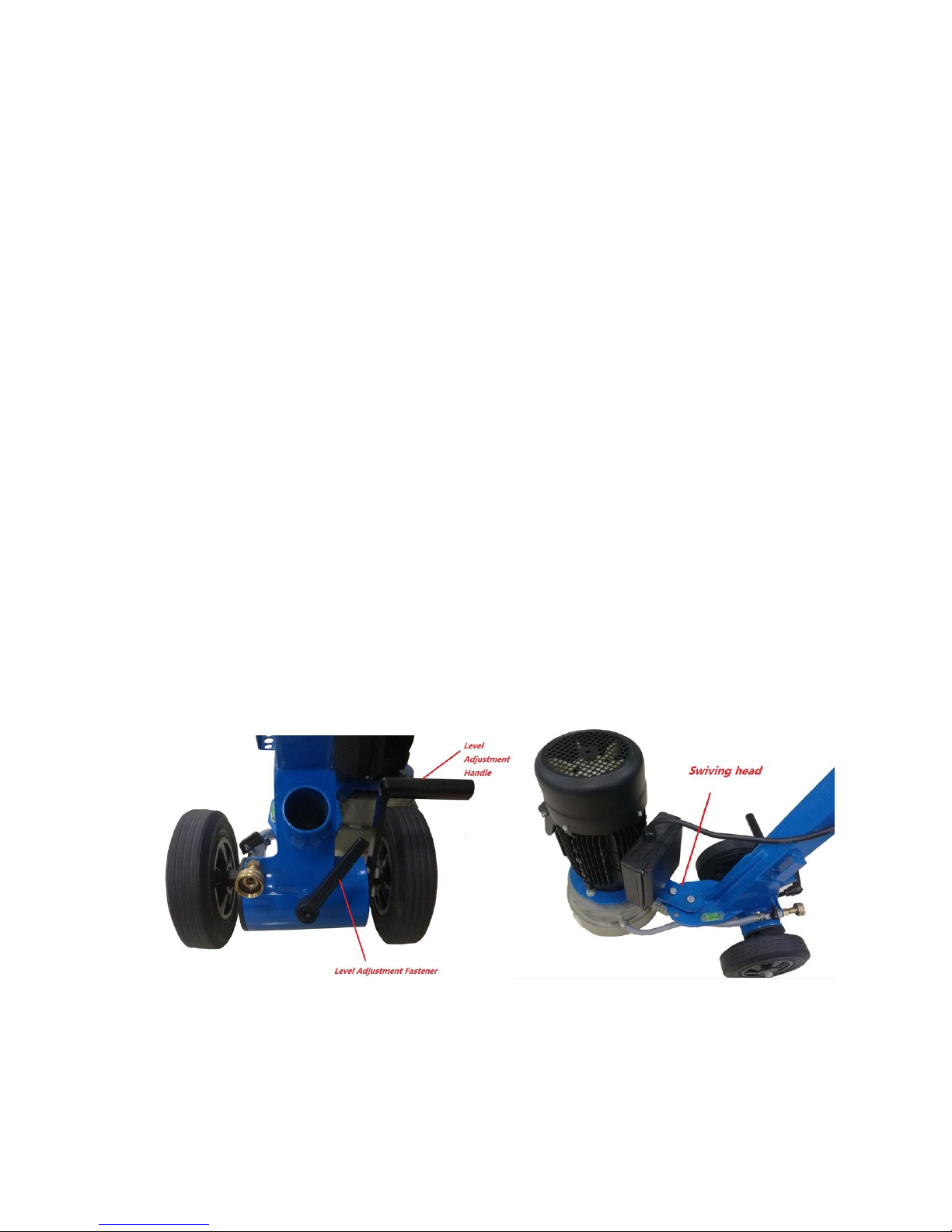
43 .FG10-043 adjust handle 1
44 .FG10-044 M8X20 hexagon screws 2
45 .FG10-045 Positioning clamping claw buckle SHMDJ71510 1
46 .FG10-046 Level bubble 1
26
Table of contents
Other CM Floor Machine manuals