CMX EVAC-500 User manual

Digital Voice Alarm & Evacuation System
EVAC-500/EVAC-240
EVAC-500RT/EVAC-240RT
EVAC-500FM
EVAC-500TM
EVAC-500RM
EVAC-12KD
EVAC-500SFT
INSTALLATION AND OPERATION MANUAL

EVAC-500 Voice Alarm & Evacuation System Operation Manual
1 / 42
CONTENTS
About the Manual-----------------------------------------------------------------------------------------------------------------------2
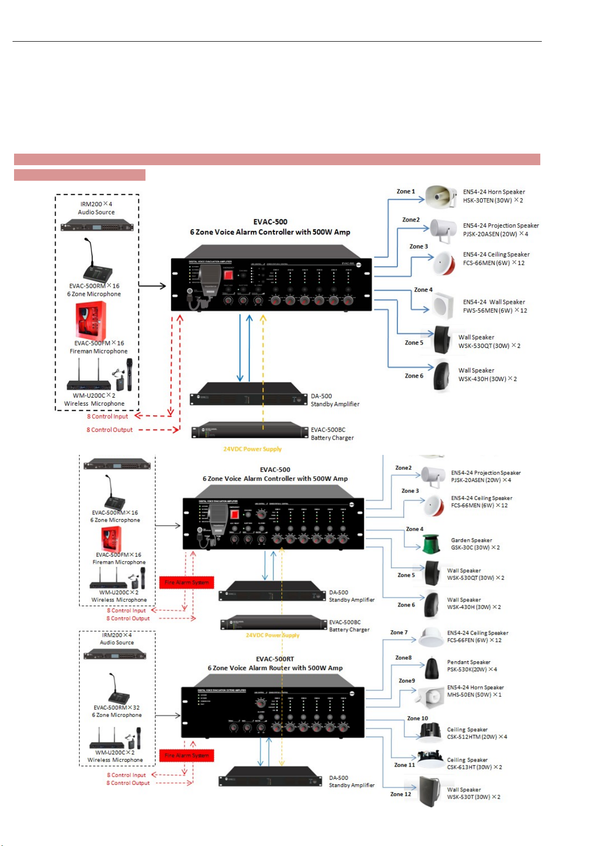
System Overview& Features & System Capacity ...................................................................................... 3
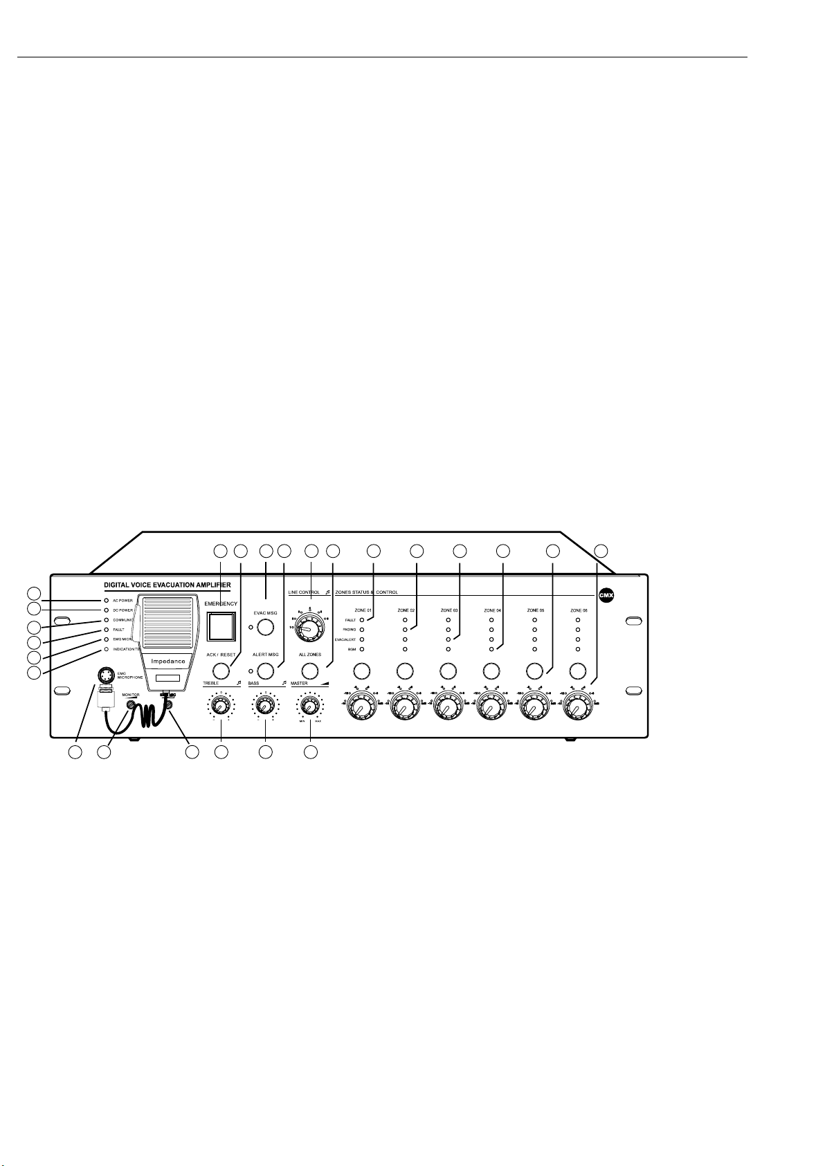
1. Host and Extension Host EVAC-500/EVAC-500RT ........................................................................... 4-11
1.1. Front Panel ....................................................................................................................................... 4-7
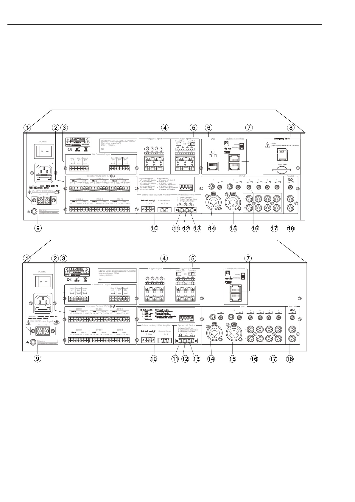
1.2. Rear Panel ........................................................................................................................................ 7-9
1.3. Dipswitch Setting of Host and Extension Host------------------------------------------------------------------------10
1.4. Technical Specifications ....................................................................................................................... 11
2. Fireman’s Microphone EVAC-500FM ............................................................................................... 12-15
2.1. Front Panel and Rear Panel ........................................................................................................... 12-15
2.2 Technical Specifications ........................................................................................................................ 15
3. Touch Screen Remote Microphone EVAC-500TM ........................................................................... 16-19
3.1. Front Panel and Rear Panel ........................................................................................................... 17-18
3.2 Technical Specifications ........................................................................................................................ 18
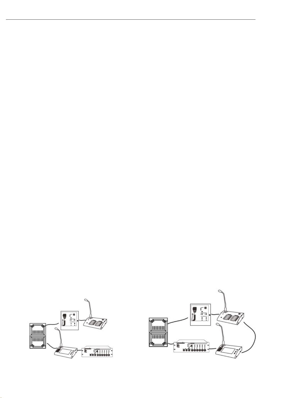
3.3. System Connection Diagram Example---------------------------------------------------------------------------------19
4. Remote Paging Microphone EVAC-500RM & Keypad EVAC-12KD .............................................. 19-23
4.1. Front Panel and Rear Panel ........................................................................................................... 20-22
4.2 Technical Specifications ........................................................................................................................ 22
4.3. System Connection Diagram Example---------------------------------------------------------------------------------23
5. Overall System Operation Guidance ............................................................................................... 23-27
5.1. Background Music System Broadcast ................................................................................................. 23
5.2. Manual Emergency Broadcast ............................................................................................................ 23
5.3. Auto Emergency Broadcast------------------------------------------------------------------------------------------------24
5.4. Emergency Microphone Announcement ............................................................................................. 24
5.5. General Announcement From Remote Microphone ............................................................................ 24
5.6. BGM Broadcast & Microphone Announcement from Software-----------------------------------------------24-28
5.6.1. Via Software BGM Broadcast ........................................................................................................... 26
5.6.2. Via Software Microphone Broadcast ---------------------------------------------------------------------------------28
6. System Software EVAC-500SFT .......................................................................................................... 29-41
6.1. Icon Introduction………………………………………………………………………………………..……… 29
6.2. Computer Configuration ........................................................................................................................ 30
6.3. Software Operation ........................................................................................................................... 31-41
6.3.1. Log In & Password. ............................................................................................................................ 31
6.3.2. Introcution of Menu Bar & Tool Instruction ......................................................................................... 32
6.3.3. Control Menu. ..................................................................................................................................... 33
6.3.4. Zone Control Configuration. .......................................................................................................... 33-36
6.3.5. Fire Alarm Rules Configuration ..................................................................................................... 36-38
6.3.6. Zone Group Configuraiton ............................................................................................................. 38-39
6.3.7. Priority Configuration. ......................................................................................................................... 39
6.3.8. Log In Event Query ............................................................................................................................ 39
6.3.9. Others……………….. .................................................................................................................... 40-41
6.3.9.1. Change Password. .......................................................................................................................... 40
6.3.9.2. Proof Host Time. .............................................................................................................................. 41
6.3.9.3. Speaker Impedance Error Adjustment. ........................................................................................... 41
7. System Maintenance Notice ..................................................................................................................... 42
8. After Sales Service ..................................................................................................................................... 42
9. Warranty ...................................................................................................................................................... 42

EVAC-500 Voice Alarm & Evacuation System Operation Manual
2 / 42
About the Manual
1. Purpose: Provide installation, configuration and operation EVAC-500 voice alarm & evacuation system.
2. Target reader: Professional technician after training of voice alarm & evacuation system.
3. Terminology
Host-EVAC-500 or EVAC-240, Extension host- EVAC-500RT or EVAC-240RT, Remote Microphone-EVAC-500RM,
Touch screen remote Controller- EVAC-500TM, Fireman’s Microphone- EVAC-500FM, Keypad—— EVAC-12KD
The software of this system will be continuously upgraded, but backward compatibility. Please note the company's
website real-time information.

EVAC-500 Voice Alarm & Evacuation System Operation Manual
3 / 42
System Overview
The EVAC-500 voice evacuation system is EN54-16 certified public address & voice evacuation system. The all in one
voice alarm & evacuation controller built-in remote PC software, zone paging controller, all main signal line monitoring,
amplifier changeover, speaker line supervision, power supply monitoring and power amplifier, voice recorder, SD card,
emergency microphone and fire alarm interface. The voice evacuation controller is innovated with DSP (digital signal
processor) to ensure its hi-fi audio performance and superior signal processing in case of commercial announcement
and emergency evacuation. Each controller built-in 6 zone speaker outputs, rated power output at 500W or 240W. The
voice evacuation controller shall be pre-set through the supplied software over microphone number, zone number, zone
loading, speaker monitoring, fire alarm mode, alert/EVAC message zone output, AC/DC etc, then synchronized the
setting to master controller and router. The voice evacuation system is strictly follow the Construction products
Regulation(EU)No 305/2011: EN54-16:2008 Voice Alarm Control and Indicating Equipment.
Feature:
EN54-16 certification No. I/ISEETC. 000620190305.
Digital voice evacuation system all in one solution.
Integration of voice evacuation controller, remote PC software, zone paging controller, all main signal line
monitoring, amplifier changeover, speaker line supervision, power supply monitoring and power amplifier, voice
recorder, SD card, emergency microphone and fire alarm interface.
Auto broadcasting EVAC and alert 256 voice messages to pre-set zones.
Customized alert, evacuation & business message stored at SD card.
AB speaker line surveillance to avoid any speaker line failure.
Back-up power amplifier management.
Up to 120 zones by cascaded more router EVAC-500RT.
Support 32 units of remote paging microphone EVAC-500RM & EVAC-500TM.
Support external connection of fireman microphone EVAC-500FM.
Redundant network cabling backup through CAT6 cable loop connection.
8 supervised control inputs & 8 control outputs, 1 fault, 1 reset & 1 EVAC relay outs.
Logs and fault events auto recording.
System Capacity-120 Zones:

EVAC-500 Voice Alarm & Evacuation System Operation Manual
4 / 42
1. Host & Extension Host EVAC-500/EVAC-240 & EVAC-500/EVAC-240RT
EVAC-500 & EVAC-240 is the core of voice alarm system, built with 500W/240W digital amplifier, enable to manual or
auto broadcast the emergency message, also fireman’s microphone evacuation is also possible under emergency,
system capacity up to 120 zones with paging and background music functions, monitoring includes amplifier failure,
speaker line failure, emergency message and emergency microphone supervision.
Emergency message format of *.wav.
EVAC message number shall be less than 255 in the file root of “evac_message/” & “alert_message/” & “prompt/”.
Make sure the software standby amplifier configuration is same as real amplifier wiring, otherwise, the host
EVAC-500 will not auto standby to backup amplifier without software correct configuration.
6 zone speaker outputs, each zone max power output is 500W, total 6 zone power output max is 500W.
With 6 external microphone or line inputs for analog microphone use or external audio sources input.
With control input and control output to inter-work with third party system.
With 3000 events history record includes power module, fireman mic, EVAC message, amplifier & speaker line.
System capacity of 32 units remote paging microphone up to 600 meters through CAT6 straight cable.
System support redundancy wiring among remote paging microphone, host and extension host within 600 meters.
1.1. EVAC-500 & EVAC-500RT Front Panel
19 20 21
7 9
22
8 10 11
23 24
12 1413 15 16 17 18
3
4
5
6
1
2
1-AC Power Indicator.
Green----means currently host AC supply normal;
Yellow----means currently host AC supply failed.
2-24V DC Indicator.
green – means current host 24V DC standby power supply is normal;
extinguish----means Current host has no 24V DC backup power supply;
Yellow----means current host 24V DC backup power failure.
3-Communication Indicator between Host and Extension Host.
Yellow----means no logical or physical connection between host and extension host;
extinguish----means no logical or physical connection between EVAC-500SFT with host;
Green----means currently device connection is normal.

EVAC-500 Voice Alarm & Evacuation System Operation Manual
5 / 42
4-Fault Indicator.
Off means system working well unless the dipswitch PIN of all supervision function is disable on rear panel; yellow
means system fault, otherwise press “ACK/REST” to restore the system.
5-Emergency Microphone Indicator.
Yellow----means emergency microphone lost or faulty; Green----means working well; extinguish----means microphone
is normal but it is not working.
6-Indication Test Button.
Press the button to light on the LED indicators of all equipments include host, extension and paging microphone to test
the indication working well.
7-Emergency Button.
Red flash—emergency mode; extinguish--normal mode.
Making Emergency Broadcast:
a) Emergency broadcast will be activated by manual press the button and red light flashing.
b) Auto emergency broadcast will be activated by the trigger inputs on the rear panel of host and extension unit and red
light flashing.
Reset the Emergency Mode:
a) Press the “ACK/Reset” button on the front panel to exist the emergency mode to terminate the emergency broadcast
and terminate the zone output.
b) Input a reset signal to the emergency control input terminal on the rear panel of the EVAC-500 which has been
assigned a reset function. These events history could be recorded and inquired in the software history record.
8-ACK/RESET Button
a). If the system various modules work normal or abnormal system module diagnosis but press the button when the
indicator "FAULT" light is not flashing, equipment do not do any processing,
b). If the system module in the diagnosis of abnormal, "FAULT" of FAULT indicator light flashing, press some button,
"FAULT" stopped lighting from blinking, blinking indicating its disabled state ,Buzzer to stop till To the new module
detects abnormal after heavy shine again "FAULT" LED lamp and start the buzzer hint user,
c). When the current partition has output, press the build close the current audio output, quick exit and quit play.
9 & 10-EVAC MSG & ALERT MSG
Green——“EVAC MSG/ALERT MSG” Voice is in broadcast information;Yellow——“EVAC MSG/ALERT MSG” Lose
voice information or loss SD card;Extinguish—— “EVAC MSG/ALERT MSG” Normal.
Note: 1."EVAC voice information" refers to the EVAC voice ALERT and voice;2. If you need to manually play EVAC
voice messages,Need to enter the emergency mode, Then press the voice messages button; 3. System default
“EVAC” Voice priority is higher than "ALERT". Can change the priority through the EVAC - 500 SFT configuration..If not
special application requirements, please do not change it.
11-Line Input Selector
Mainly used to select the external line input to this host or extension.
Only the host audio tracks can be output to the extension of the host while line extension of the host audio won't scale

EVAC-500 Voice Alarm & Evacuation System Operation Manual
6 / 42
output to other host;
The host line audio can controlled by EVAC - 500 SFT or EVAC - RM/RME and EVAC-500FM/EVAC-500TP.
Note:The choice of the current user can see through the EVAC - 500 SFT interface,To change the different audio
output,Only through use to choose from the panel.
12-All Zones
To select all six zone outputs open or close at the same time.
13-Zone Fault Indicator.
Yellow-The current partition A and B or A or B speaker impedance change, may be open or short circuit. Extinguish-The
current speaker zone loop impedance changes within the impedance of the speaker when it was pre-set.
Note:When the host or extension host access system according to the project wiring work needs a resistance to
proofread before obtaining the loop impedance value of the current speaker, please follow below steps:
Unplug the host back row ID switch. 7,Until hear buzzer sing alternately or see panel lights flashing after "FAULT"
then, Put the 7th ID switch it on. When the speaker circuit impedance change more than the current host or extend
the host for the impedance value plus or minus 10% ~ 10%Will record the current changes and inform the user in
the form of light. Zone detection sensitivity is more than 20W
14-Paging Indicator.
When paging, can manually close the zones where no need paging or add new zones.
15-EVAC/ALERT Indicator.
When EVAC and alert emergency broadcast is working, the indicator will be light on.
16-BGM Indicator.
When background music broadcast is working, the indicator will be light on
.
Note:Manual broadcast voice messages need choose audio first, then, choose output zone, For example, if you
want output line 3 in 3rd zone, you can choose line 3 audio then choose 3rd zone. You also can choose 3rd zone, then,
choose line 3. Two ways are the same, normally, we choose zone firstly, then choose audio. In this way, each zone will
output audio at the same time, We also can control different zones from the EVAC - 500 SFT operation.
17-Zone Selector.
To select individual six zone output open or close.
18-Zone Output Attenuator.
Increase or decrease the individual zone speaker output loudness at 6 levels and max control of -15dB.
19-Emergency Microphone Input.
Input for the emergency microphone or fireman microphone of priority.
20-Monitor Speaker Attenuator.
Increase or decrease the built-in monitor speaker loudness.
21-Emergency Microphone Gain Control.
It is used to adjust the emergency microphone input sensitivity.
22-Treble Control.
Increase or decrease the overall treble output.

EVAC-500 Voice Alarm & Evacuation System Operation Manual
7 / 42
23-Bass Control.
Increase or decrease the overall bass output.
24-Master Volume Control.
Increase or decrease the overall master volume output.
1.2. EVAC-500 & EVAC-500RT Rear Panel
1-24V DC Power Input.
24V DC input for sealed lead-acid battery, UPS or equivalent product;
Note:
1. Use EN54-4 certificated power supply when EN standard required.
2. Do make sure the 24V DC could meet the minimum working current of the host. For example, full loading of
EVAC-500 at 500W, the lead-acid battery shall supply the current higher than 27A, battery capacity higher than
27Ah and working time shall be full loading*27Ah*1.2 hours.
2-Six A&B Speaker Zone Output
external constant voltage transformer loudspeaker and 3 wired volume control;
output voltage is: 0 ~ 100 v;

EVAC-500 Voice Alarm & Evacuation System Operation Manual
8 / 42
Note: Note: please connection at least one zone of speaker circuit after completing the wiring. It will be OK when not all
speaker zones output are connected with speakers. Please also ensure the total speaker loading is less than 80% of the
host built-in amplifier loading.
3- Six 24V Relay Output
external four wire system programmable;
rated output current for each road: 0.2 A;
Note: output shall not be greater than the total power 28 w;
4-8 Program Control Outputs.
These outputs usually shall be keep open, which could be programmed in the software to activate it or terminate it
auto or manually.
5-8 Program Control Inputs.
These inputs usually shall be keep open, which could be programmed in the software to activate it or terminate it
auto or manually.
6-LAN Input for PC Software.
It is mainly used to connect to EVAC-500SF for setting, program and manual operation.
Note:
1) Default IP address: 192.168.1.168, Communication port number: 16888.
2) Reset the IP address to default by enable & disable once time the dipswitch 6th PIN on the rear panel of host.
3) If you dislike the default IP address, please up the 5th dipswitch to open DHCP function. Make sure your
network router opened up the DHCP function. This function is mainly used to upgrade new features to use in the
future, the current system before unplug ";
4) Support PC software directly connection to EVAC-500,automatic identify cross and straight cable. All
communication cable shall be meet TIE/EIA-568B standards including connection to extension and remote paging
microphone.
7- Two RJ45 Communication Ports.
Use straight CAT6 cable to connect the extension controller EVAC-500RT to the host, system capacity of 19 units
extension and communication distance is up to 600 meters. Support microphone loop connection or star connection as
above remote paging microphone pictures, the system software will auto distinguish different kinds of cable connection.
Also connection ports for extend EVAC-500RM/EVAC-500FM/EVAC-500TM/EVAC-500RT
support loop connection or start connection(as shown in the figure below), automatic identification of software
- to maintain the operation of the system is reliable & stable recommend to use the loop connection.
Closed or loop connection mode Star connection

EVAC-500 Voice Alarm & Evacuation System Operation Manual
9 / 42
8- Evacuation Message SD Card.
The emergency message memory card is real time monitored, tested memory capacity of 32G, never plug out this
card during work, otherwise the event record and program will be lost. The root of emergency message as below
picture, there is each one Alert and EVAC default messages, edit, add or delete or replace these messages are
possible done by professional technician, these messages will be real time supervised. “Log” file is log in event
record, which could be inquired or download in software EVAC-500SF. “Prompt” means chime before
announcement, so customized chime could be replaced the default one in EVAC-500RM, this chime message is
not real time monitored, only will be reviewed once after power on, so no chime or file lost will be not warned as
fault. Max message number is 255.
9-Ground Earth Line
Please connect this earth line to the ground for safety use.
10-Backup power amplifier interface
power signal inputs of 100V or 70V,
“audio signal output shall be balanced
11-System Fault Output
In case of any fault for the system, this output will closed circuit to trigger output and normally default is open
circuit.
12-System EVAC State Output
In case of EVAC, the output will closed circuit to trigger output and normally default is open circuit.
13-Emergency Reset Input (Longer than or equal to 0.5S relay closed-circuit input, used to connect CIE
device and realize the on-line control)
In case of emergency, use one closed circuit input to reset it to back to normal status
When it is operated in a normal mode, it is not processed and ignored.
14 & 15-MIC/LINE Input
Balanced MIC/LINE 1-2 Inputs by COMBO type
16-MIC/LINE Input Gain Control
Please change the gain to match with microphone or line input, since their sensitivity is different, so as to avoid any
noise.
17- Line Input 3-6
Stereo line input from audio sources player for background music system use, each input with gain control.
18-REC Out
Output to recorder and External amplifier, with gain control. Please make sure the output audio volume big
enough and non-distorted.

EVAC-500 Voice Alarm & Evacuation System Operation Manual
10 / 42
1.3. Dipswitch Setting of Host & Extension Host
1.3.1. Host Configuration Dipswitch (UP means “ENABLE” and DOWN means “DISABLED”)
1 - “Supervision Enable” means to on/off the system all supervision or monitoring functions, we suggest to
disable or off it during test or before full system wiring, please on this dipswitch after full wiring and software
program.
2 - “DC Supply Enable” means the host or extended host whether has been 24V DC power supply, if yes,
please program it in the software and on this dipswitch, otherwise, please off this dipswitch. The system host will
be fault if software program is not consistent with 24V DC power supply conditions.
3 - “ Trigger Mode” here is used to select the two way control inputs whether by closed control input or
level control input. “ENABLE”, means by the relay closed control input, “DISABLED” means the by way of level
control input.
4 “Spare Amp Config” means the host or extended host whether has been configured with standby power
amplifier, if yes, please also program it in the software, thus when the host amplifier failure, the standby amplifier
will automatically backup the main amplifier failure, since the host built-in auto amplifier failure changeover.
5 - “DHCP Enable” refers to selection mode of host IP address. “ENABLE” means the IP address of host
will use the IP address automatically allocated by the router, and “DISABLED” means that the host will use the
static IP address;
Consult the above “6 – Ethernet Port”;
6 - “Reset IP Address” means to reset the host IP address from its default IP address 192.168.1.168, and
port number is 16888. Only ensure the software PC’s IP address is same gateway with the host IP address, thus
the communication and program could be well done.
7 - “Impedance Calibration” means to calibrate the zone speaker loading impedance, after the software
program of speaker impedance value and fluctuation percentage, then the system host will activate the speaker
zone impedance surveillance, once there is zone speaker impedance change because of short circuit or open
circuit, the host and software both will be failure warning. Please ensure that the current speaker zones are all
closed while calibrating the modeling;
8 - “Speaker Line Supervision” to on/off the zone speaker supervision or monitoring.
1.3.2. Extended Host Configuration Dipswitch (UP means “ENABLE” and DOWN means “DISABLED”)
1 - “1-5 Equipment ID” these 5 pin of dipswitch is used to set up the different ID of extended host.
(00000 means non-configured, 00001 means 01 extended host, 00010 means 02 extended host).
6 - “DC Supply Enable” means the host or extended host whether has been 24V DC power supply, if
yes, please program it in the software and on this dipswitch, otherwise, please off this dipswitch. The system
host will be fault if software program is not consistent with 24V DC power supply conditions.
7 - “Spare Amp Config” means the host or extended host whether has been configured with standby
power amplifier, if yes, please also program it in the software, thus when the host amplifier failure, the standby
amplifier will auto backup the main amplifier failure, since the host built-in auto amplifier failure changeover.
8 - “Speaker Line Supervision” to on/off the zone speaker supervision or monitoring.

EVAC-500 Voice Alarm & Evacuation System Operation Manual
11 / 42
1.4. Technical Specifications
Model EVAC-500/EVAC-240 EVAC-500RT/EVAC-240RT
Description Host Extension Host
AC Electrical Part Power Supply AC220V-250V, 50/60Hz
Power Consumption 650W
Max Current <3A
Fuse 250V/5A, low speed type
DC Electrical Part Power Supply 24V DC, 20V-27.5V
Max Current <27A
Emergency
Microphone
Sensitivity 5mV
Impedance 600Ω
Line Input 1-6 THD <1%, at rated power output, 1kHz
Sensitivity 775mV
Impedance 10kΩ
S/N Ratio >70dB
Control Input & Output
Fault Output Closed circuit, no voltage
EVAC State Output Closed circuit, no voltage
EVAC Reset Input Closed circuit, no voltage, T>0.5s
8 Program Control
Output
Closed circuit, no voltage
8 Program Control
Input
Way-1: Closed circuit, no voltage
Way-2: Level input and max 3.3V
Emergency Message Format WAV
Memory Card SD memory card
Capacity 32G
Message No. 255 Max
Period 10 years
SD card FAT/FAT32
Log Event
Format HEX
Storage Way Nand Flash
Event No. 1000
Period 10 years
Working Environment Operation Temp +5 ~ +40℃ ℃
Storage Temp -20 ~ +70℃ ℃
Relative Humidity < 95%
Mechanical Spec Dimension 484x132x405mm
Net Weight 11.2kg
Rack Mount 19” rack mount type
Finish Aluminum plate and metal case in black

EVAC-500 Voice Alarm & Evacuation System Operation Manual
12 / 42
2. Fireman’s Microphone——EVAC-500FM
Feature:
Fireman’s microphone as remote control of voice evacuation system EVAC-500.
EN54-16 Certified fireman’s microphone.
Emergency (EMG) microphone with priority.
EMG state and fault visual indicators.
The fireman’s microphone unit is fully real time monitored.
Four programmable buttons and EVAC/Alert.
Remote pre-recorded message broadcast in case of emergency.
Support DC 24V phantom power supply from the controller.
With AC, DC, fault, MIC and indication test four indicators.
With emergency activation button for all zone EVAC operation.
Communication distance up to 600 meters.
Communication with controller through CAT6 cable loop redundancy connection.
Each voice evacuation system supports 32 units of fireman microphone maximum.
With lock and key to ensure access permission.
Description:
The EVAC-500FM fireman’s microphone is EN54-16 certified and designed exclusively for EVAC-500 public address &
voice evacuation system. The fireman’s microphone is a surface mounted cabinet containing a first help and echo
cancelling microphone, state indicator, pre-recorded message announcement and live announcement. The fireman’s
microphone is typically used in case of emergency to help the fireman to enter or acknowledge the emergency state,
and acknowledge and reset the fault state. Emergency or alert pre-recorded messages can be broadcasted to
pre-assigned zone or all zone, and fireman live calls can be made with priority. The fireman’s microphone is a remote
control that has dedicated buttons and indicators for fireman’s operation only. The remote control has no zone selection
but with programmable buttons. Four LED indicators show the EVAC status and calls that are active in the system. The
fault indicators show detailed information of a fault in the system. Connection to the Voice Evacuation System is via
standard, shielded CAT-6 cable and RJ45 connectors in a redundancy loop up to 600 meters. The wall mount type
fireman’s microphone is suitable for indoor & outdoor both applications. The voice evacuation system is strictly follow
the Construction products Regulation(EU)No 305/2011: EN54-16:2008 Voice Alarm Control and Indicating Equipment.

EVAC-500 Voice Alarm & Evacuation System Operation Manual
13 / 42
2.1. Front Panel and Rear Panel:

EVAC-500 Voice Alarm & Evacuation System Operation Manual
14 / 42
1—Power Indicators
1). AC POWER:
Yellow —— The system has equipment, but AC power failure;
Green —— The system has equipment and AC power is normal;
2). DC POWER:
Yellow —— The system has equipment, but DC power failure;
Green —— The system has equipment and DC power is normal;
2— Fault indicator
Yellow (NO SPARKLING)——Indicates that the current equipment or system has equipment module failure, The
user has identified the fault, Pls click “FAULT ACK”.
Yellow (SPARKLING)—— Indicates that a new fault exists in the device, To inform the user, At this point the user is
not confirmed.
Distinguished indicators—— All modules of the system work normally.
3— Emergency Microphone indicator
Yellow —— Means fault;
Green —— Means working;
Distinguished indicator —— Means communication is normal;
4— Indication Test
In any state,Press the test indication button on the host,the light on the LED will be lighted up. It is used to confirm
whether the LED is working properly;
5—Emergency Button
Red flash—emergency mode; extinguish--normal mode.
Making Emergency Broadcast: a) Emergency broadcast will be activated by manual press the button and red light
flashing. b) Auto emergency broadcast will be activated by the trigger inputs on the rear panel of host and extension unit
and red light flashing.
Reset the Emergency Mode: a) Press the “ACK/Reset” button on the front panel to exist the emergency mode to
terminate the emergency broadcast and terminate the zone output. b) Input a reset signal to the emergency control
input terminal on the rear panel of the EVAC-500 which has been assigned a reset function. These events history could
be recorded and inquired in the software history record.
6— FAULT ACK
a). If the system various modules work normal or abnormal system module diagnosis but press the button when the
indicator "FAULT" light is not flashing, equipment do not do any processing;
b). If the system module in the diagnosis of abnormal, "FAULT" of FAULT indicator light flashing, press some button,
"FAULT" stopped lighting from blinking, blinking indicating its disabled state, Buzzer to stop till To the new module
detects abnormal after heavy shine again "FAULT" LED lamp and start the buzzer hint user;
c). When the current partition has output, press the build close the current audio output, quick exit and quit play;
7—EVAC MSG & Alert MSG
Green——“EVAC MSG/ALERT MSG” Voice is in broadcast information;Yellow——“EVAC MSG/ALERT MSG” Lose
voice information or loss SD card;Extinguish—— “EVAC MSG/ALERT MSG” Normal.
Note: 1."EVAC voice information" refers to the EVAC voice ALERT and voice;2. If you need to manually play EVAC
voice messages,Need to enter the emergency mode, Then press the voice messages button; 3. System default
“EVAC” Voice priority is higher than "ALERT". Can change the priority through the EVAC - 500 SFT configuration. If not
special application requirements, please do not change it.
8—Four Function Button & Indicators
Light on means working. Flash means zone has been selected. Extinguish means no working.

EVAC-500 Voice Alarm & Evacuation System Operation Manual
15 / 42
9— Lock with Key
10 & 11— Cable Outlet
12—ID Configuration Dipswitch.
Upward means enable and downward means disable. 1st to 5th PIN means ID of binary system. 6th PIN upward means
normal paging mode and downward means PPT paging mode. 7th PIN upward means individual zone and downward
means group, group could be defined with multiple zones. 8th PIN is indication test, downward means start the LED
indication test, all LED indicator will be from red-green-yellow then to normal state. Below is example of remote paging
mic ID from No 1 to No 4.
2.2. Technical Specifications
Electric Part
Phantom Power
Voltage 20V ~ 27.5V
Maximum Current Less than 0.2A (24V power supplier,all the LED on the front panel will be lighted
up, it is paging state)
Power Consumption Less than 3W
Performance Index
MIC
SPL 30mV
Mechanical Specifications 300* 300 * 107 mm
N.W. 3.9KGS
Installation Wall Mount Type
Color Red
Environmental Requirement
Operating Temperature +5℃ ~ +40℃
Storage Temperature -20℃ ~ +70℃
Relative temperature <95%(without condensation)

EVAC-500 Voice Alarm & Evacuation System Operation Manual
16 / 42
3. Touch Screen Remote Microphone——EVAC-500TM
Feature:
Touch screen remote microphone or call station
EN54-16 Certified remote microphone
Business & commercial zone live announcement use
Multiple zones, single zone & all zone paging
Each microphone of 120 zone capacity
Support 32 remote microphones of loop redundancy connection
The remote microphone unit is fully real time monitored
Support PPT and lock type two modes
Shielded CAT-6 cable up to 600 meters
Power supply from EVAC-500 controller
Description:
The EVAC-500TM touch screen remote microphone is EN54-16 certified and designed exclusively for EVAC-500 public
address & voice evacuation system. The remote microphone is used for business and commercial live announcement
to selected zones or all zones. The remote microphone is designed of 120 zone with busy & working indicators. Up to
32 units of remote microphone could be connected to the voice evacuation system via shielded CAT6 cable and RJ45
connectors in a redundancy loop up to 600 meters. The talk button maybe a PTT or lock type pre-set by the dipswitch
on the rear of the microphone. Green LED indicates the microphone and zone active status. The remote microphone is
24VDC powered by the EVAC-500 controller. The voice evacuation system is strictly follow the Construction products
Regulation(EU)No 305/2011: EN54-16:2008 Voice Alarm Control and Indicating Equipment.

EVAC-500 Voice Alarm & Evacuation System Operation Manual
17 / 42
3.1. Front and Rear Panels
1—HD display
2— Power indicator
3— All Zone
Select all zone for paging methods:
1. Users can choose all zone button on the LCD display
2. The user can select the all zone button
4—Talk button
When the user confirms the selection of the zone, press this talk button on LCD screen " " or press
talk button to make announcement;
Note: When the gooseneck is ready for talk, there is round ring indicator will be illuminated.
5— Monitor speakers
:
Used to monitor the user's current paging sound, this output can be closed and open through the interface and the
volume is adjustable, as shown below:

EVAC-500 Voice Alarm & Evacuation System Operation Manual
18 / 42
6— Two RJ45 Communication Port with Host
There are two RJ45 communication ports, one for host and the other port is for next remote microphone hand-in-hand
connection or loop connection back to the host for redundancy connection. For these two RJ45 ports, there is no
distinction between the primary and the secondary port.
7— Monitor output
This monitor output has priority over the built-in monitor
8— Line input
This is used to input external audio source player instead of MIC output audio, while the presence of line input
priority;
9— Main power switch on/off
10—External 24V DC Power Supply Input
Note: When the device and the host communication distance is longer than 100m, please use external power supply,
specifications: 24VDC / 1A.
3.2. Technical Specifications
Electrical Specifications
Phantom power
voltage 20V ~ 27.5V
maximum current less then 0.5A (24VDC,front panel LED lighting,Paging state)
Power consumption less than 7W
performance index
line input
sensitivity 775mV
impedance 10kΩ
SNR(Signal to Noise Ratio) >70dB
MIC
sensitivity 50mV
Mechanical Specifications
Dimension 282* 153 * 52 mm
N.W. about 1.3kg
Install Tabletop
Color Black
environmental requirement
Operating temperature +5℃ ~ +40℃
Storage temperature -20℃ ~ +70℃
Relative temperature <95%(without condensation)

EVAC-500 Voice Alarm & Evacuation System Operation Manual
19 / 42
3.3. System Connection Diagram Example:
4. Remote Microphone and Keypad—EVAC-500RM & EVAC-12KD
Feature:
Remote microphone or call station of voice evacuation system EVAC-500.
EN54-16 Certified fireman’s microphone.
Business & commercial zone live announcement use.
Multiple zones, single zone & all zone paging.
Each microphone of 12 zone capacity.
Up to 120 zones by cascaded the zone keypad EVAC-12KD.
Support 32 remote microphones of loop redundancy connection.
The remote microphone unit is fully real time monitored.
Support PPT and lock type two modes.
Shielded CAT-6 cable up to 600 meters.
Power supply from EVAC-500 controller.
Description:
The EVAC-500RM remote microphone or call station is EN54-16 certified and designed exclusively for EVAC-500
public address & voice evacuation system. The remote microphone is used for business and commercial live
announcement to selected zones or all zones. The remote microphone is designed of 12 zone buttons with busy &
working indicators. One or multiple external 12 zone expansion keypad EVAC-12KD could be cascaded together for up
to 120 zone operation. Up to 32 units of remote microphone could be connected to the voice evacuation system via
standard, shielded CAT-6 cable and RJ45 connectors in a redundancy loop up to 600 meters. The talk button maybe a
PTT or lock type pre-set by the dipswitch on the rear of the microphone. Green LED indicates the microphone and zone
This manual suits for next models
8
Table of contents
Popular Security System manuals by other brands

USP/Emergency Caller Products
USP/Emergency Caller Products EC-1 Owner's Manual and Operating Instructions

Ingrid
Ingrid Home Security System user manual

Simon
Simon Simon installation instructions

KALEAS
KALEAS KlimaDetector operating instructions

NAPCO
NAPCO PRO410 operating instructions

ring
ring Pro Power user guide