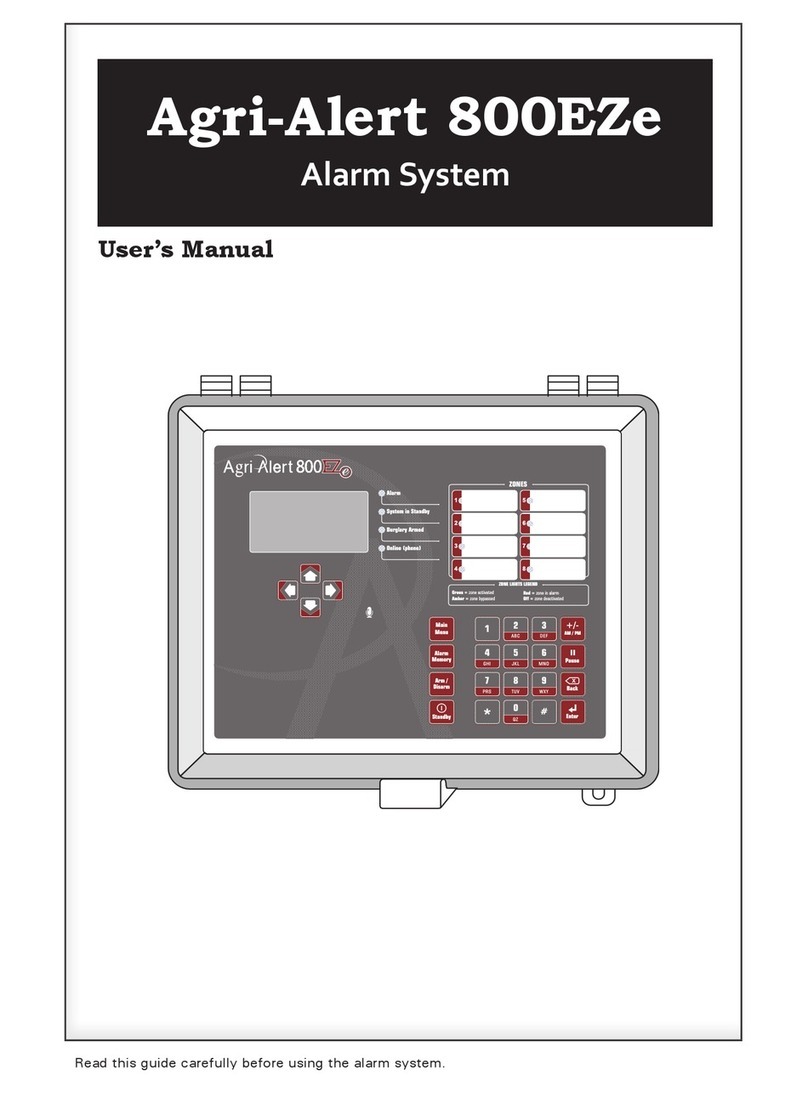
Viatron Agri Alert 400 User manual

Alarm System
Users Manual

2AA-400 rev.02
WARNINGS
The warranty can be void if this product is used in a manner not specified by the manufacturer.
Every effort has been made to ensure that this manual is complete, accurate and up-to-date. The information
contained in it is however subject to change without notice due to further developments.
Manufacturer:
Viatron Electronics
5200, Armand-Frappier
St-Hubert (Quebec)
Canada
J3Z 1G5

3
AA-400 rev.02
Table of Contents
1. INSTALLATION .......................................................... 4
1.1 Precautions ................................................................................. 4
1.2 Installation Procedure .................................................................... 4
1.3 Mounting the Equipment ................................................................. 5
1.4 Connecting the Equipment .............................................................. 6
1.4.1 Sensors ................................................................................... 6
1.4.2 Supply Inputs ........................................................................... 6
1.4.2.1 AC Power Connection ........................................................ 6
1.4.2.2 Backup Battery Connection .................................................. 6
1.4.3 Connecting the Earth Ground ...................................................... 7
1.4.4 Siren Output ............................................................................ 7
2. USER-INTERFACE ....................................................... 8
2.1 Faceplate .................................................................................... 8
2.2 Internal Switches .......................................................................... 9
3. CONFIGURING THE ZONES .........................................10
3.1 Enabling/Disabling the Zones .......................................................... 10
3.2 Setting Zone Contacts .................................................................. 10
3.3 Setting the Recognition Time ......................................................... 10
3.4 Setting the Alarm Output Status .................................................... 10
4. CONTROLLER'S OPERATION ......................................11
4.1 Cancelling/Acknowledging an Alarm ............................................... 11
4.2 Activate/Bypass a Zone ................................................................ 11
5. APPENDIX ................................................................12
Appendix A: Fuse Types ....................................................................... 12
Appendix B: Maximum wire lengths ....................................................... 12
Appendix C: Backup battery life span ...................................................... 12
6. TECHNICAL SPECIFICATIONS .....................................13
7. WIRING DIAGRAM.....................................................14

4AA-400 rev.02
1. INSTALLATION
1.1 Precautions
Read the following instructions com-
pletely before connecting or operat-
ing the unit. Failure to comply with
the instructions in this booklet may
result in a malfunction or injury.
The room temperature where the alarm system
is located must always remain between 0°C to
40°C (32°F and 104°F).
To avoid exposing the controller to harmful
gases or excessive humidity, it is preferable to
install it in a corridor.
Do not spray water on
the controller!
For Customer Use
Enter below the serial number located on the
side of the controller and retain this informa-
tion for future reference.
Model number: AA-400
Serial number:
Date installed:
1.2 Installation Procedure
What you need:
- AA-400 system including an
independent battery enclosure:
- 12VDC / 7.5AH sealed lead acid
battery;
- 16.5VAC/40VA transformer.
To avoid electrical shocks and
equipment damage, turn off the
breaker on which is connected the
unit before configuring the main
board or making connections to the
terminals.
•Step 1: Determine where you want to
install the system. You need an unswitched
AC power outlet nearby to operate the
system.
•Step 2: Make a list of all the sensor inputs
you will be using with the AA-400 alarm
system.
•Step 3: Mount the AA-400 alarm system
and the battery enclosure on the wall (see
section 1.3).
•Step 4: Connect a ground wire to the main
ground of the system (see section 1.4.3).
•Step 5: Hook up the battery and plug the
transformer into an AC power outlet (see
section 1.4.2).

5
AA-400 rev.02
1.3 Mounting the Equipment
The AA-400 alarm system and the battery box
should be mounted on a wall as shown in the
figure below. Pull the latch located at the
bottom of the boxes to open the enclosures.
Use 3/16” (4.75 mm) diameter screws to
mount each enclosure on the wall. Fasten the
black caps onto the mounting holes once the
screws are tightened. Make sure the covers of
the two boxes can be opened easily.
The battery enclosure has ventila-
tion openings on the sides. Make
sure they are not obstructed.
Battery Box
6” (150 mm)
plastic tubing
cable
holder
cable
holder
Alarm System
6 3/8”
(162 mm)
149 mm)
5 7/8”
(
4 1/2”
(115 mm)
6 3/8”
(162 mm)
5 7/8”
(149 mm)
Mount the battery enclosure 4 1/2” (115 mm)
from the AA-400 enclosure. Use the plastic
tubing provided to run the wires from the
battery to the alarm system. These wires are
provided with the system. The bare end hooks
up to the AA-400 alarm system.
Pass all wiring through the bottom of the
enclosure. Do not drill holes on the side or the
top of the enclosure as this may allow water to
enter the enclosure. Use a hammer and a
screwdriver to punch holes through the bot-
tom of the enclosure.
123
456

6AA-400 rev.02
1.4 Connecting the Equipment
When connecting the equipment to the termi-
nals provided on the main board and the exten-
sion cards, strip the wires as little as possible
(about 1/4” (6 mm)) to avoid electrical shorts.
Once the wires are connected, run them through
the electrical knockouts provided on the bot-
tom of the AA-400 enclosure and use a cable
holder (2 cable holders are provided for the
battery connections. You can order additional
cable holders from your dealer if needed).
1.4.1 Sensors
The terminals used for sensor inputs are num-
bered Z1, Z2, Z3 & Z4 on the main board.
Connect each sensor to a Z terminal and to its
respective ground terminal (COM). Note that
each ground terminal is used by two zones; for
example, Z1 and Z2 use the same ground.
Make sure each sensor is connected to the
proper ground. False alarms can result if the
ground wires are not properly connected.
Z1 Z2 Z3 Z4COM COM
Zone 1
sensor
Zone 2
sensor
Zone 3
sensor
Zone 4
sensor
1.4.2 Supply Inputs
1.4.2.1 AC Power Connection
The terminals marked 16 VAC on the main
board are used for connecting the transformer.
The transformer provided with the system is a
16.5 VAC/40 VA transformer. It must be
plugged into a 120 VAC / 60 Hz outlet. The F2
fuse (5A fast blow) is connected to this input.
Make sure the power source is unswitched
(i.e. there is no switch on the power outlet).
1.4.2.2 Backup Battery Connection
The terminals marked BATT are used for the
backup battery. The AA-400 system uses a
12 VDC / 7.5 AH sealed lead acid battery. No
other type of battery can be used. The battery
wires run through the tube provided, as shown
on the graph below. Make sure the positive
wire of the battery is connected to the positive
terminal. See Appendix C for normal battery
life spans.
16VAC BATTERY
SUPPLY INPUTS
+
16VAC, 40VA
TRANSFORMER
BATTERY BOX
+
ALARM SYSTEM
+
+-
-

7
AA-400 rev.02
1.4.3 Connecting the Earth Ground
The earth ground terminal of the AA-400 must
be connected to the earth ground as follows.
Use a rod at least 5/8 in (16 mm) in diameter
at least 10 ft (3 m) long. The rod must have a
clean metal surface free of paint, enamel or
other nonconducting substances. Drive the rod
at least 10 ft (3 m) into the ground. If the
bedrock is more than 47 in (1.2 m) deep, drive
the rod into the ground to bedrock level and
bury any remainder horizontally at least 2 ft
(600 mm) below ground level. If the bedrock is
less than 47 in (1.2 m) deep, bury the rod
horizontally at least 2 ft (600 mm) below
ground level (ref. article 10-702, 3d of the
Canadian Electricity Code C22.10-99).
The rod must be connected to the wire de-
scribed above. It is recommended to let the rod
going out of the ground to connect it. The wire
length must not exceed 50 ft (15 m).
10 ft ( )3 m
2 ft
()600 mm
Burying
the rod
Bedrock
<47 in (1.2 m)
EARTH
GND
3-meter
metal rod
10 ft
()3 m
2 ft
()600 mm
10 ft ( )3 m
<47 in (1.2 m)
SIREN
+
ALARM SYSTEM
It is extremely important that the
earth ground terminal be con-
nected to a proper ground to pro-
tect the electronic components
from damage due to lightning
surges and electrostatic dis-
charges. Do not use the electrical
ground for this purpose.
If outdoor connections are used,
mount the enclosure as close as
possible to the entry point of the
outdoor wiring.
An improper earth ground connec-
tion immediately voids the system
warranty without further notice.
1.4.4 Siren Output
The terminals marked SIREN are for the siren.
The voltage supplied is 12 VDC with a maxi-
mum current of 1.5 A. Note that the battery
must be hooked up if a siren is used. The F5
fuse (2A slow blow) is connected to this
output. Make sure the positive wire is con-
nected to the positive terminal of the siren.

8AA-400 rev.02
2. USER-INTERFACE
2.1 Faceplate
Zone LED Zone Zone Status
Red
(solid) Enabled No alarm.
Yellow Enabled The zone is
bypassed.
Red
(flashing) Enabled An alarm
is active.
Off Disabled Not used.
Cancel Button
When an alarm is active, press CANCEL
to disable the siren for 15 minutes.
Then, take proper actions to correct the
alarm situation.
Bypass/Activate Buttons
To stop monitoring a zone, press the
bypass button until the zone light turns
off ; to reactivate the zone, press the
bypass button until the LED turns red
(solid or flashing).
Blank spaces
Write down the description of each
zone in the spaces provided.
Blank spaces
Cancel button
Zone
status
LED
s
Bypass/
activate
button
s
System status
LEDs
Zone Status LEDsSystem Status Lights
Status LED Meaning
Alarm This LED is lit when an alarm condition
is detected.
AC Power This LED is lit when the device is
powered properly.
Low
Battery
This LED is lit when the voltage of the
backup battery is low. (On first startup,
the actual battery status is detected
after 1 minute).
Alarm
Cancelled
This LED is lit when an alarm is
cancelled for 15 minutes with the
CANCEL button. It remains lit as long
as the alarm condition is present.

9
AA-400 rev.02
2.2 Internal Switches
Internal switches are used to configure your
AA-400 controller. These switches are lo-
cated on the main board of the AA-400, inside
the enclosure.
Refer to the table below to set internal switches
1-12 to the appropriate position (please refer
to the
"Configuring the zones"
section of this
manual to get further information about the
particular function of each switch).
ALWAYS turn off power to the
AA-400 before opening the enclo-
sure.
When the alarm system is shipped,
all internal switches are set to
OFF.
ON
OFF
1
[1]
9
[2]
10
[3]
11
[4]
12
[5]
13
[6]
14
[7]
15
[8]
16
ON
OFF
[1]
1
[2]
2
[3]
3
[4]
4
[5]
5
[6]
6
[7]
7
[8]
8
8
9
16
OFF ON
1ZONE1
2ZONE2
3ZONE3
4ZONE4
5ZONE1
6ZONE2
7ZONE3
8ZONE4
9ZONE1
10 ZONE 2
11 ZONE 3
12 ZONE 4
13 SIREN ALWAYS ON INTERMITTENT (ON=10 SEC; OFF=2 MIN)
14-16
ZONE STATUS:
DISABLED
ZONE STATUS:
ENABLED
Switch #
RESERVED
RECOGNITION
TIME: 0 SECOND
RECOGNITION
TIME: 30 SECONDS
ZONE CONTACT:
NORMALLY OPEN
ZONE CONTACT:
NORMALLY CLOSED

10 AA-400 rev.02
3. CONFIGURING THE ZONES
A zone is an input configured to respond to the
type of sensor connected to it. Sensors are
installed by the user to detect alarm condi-
tions. In all, the AA-400 can monitor up to
4 different dry contact zone inputs.
3.1 Enabling/Disabling the Zones
The AA-400 can monitor up to
4 dry contact zone inputs. Set
internal switches 1-4 properly to
enable or disable the desired number of zones
(refer to the table below).
3.2 Setting Zone Contacts
Dry contacts can be either nor-
mally open (NO) or normally closed
(NC) circuits. The AA-400 sets
off an alarm when the NO contact of a zone
closes or when the NC contact of a zone opens.
Set internal switches 5-8 properly to select the
right type of contact of each zone (refer to the
table below).
If a wireless module (WM-3000Rx)
is connected to the AA-400, all
zone of the AA-400 must use the
same type of contact as for the
wireless module.
ON
OFF
8765
OFF ON
5ZONE1
6ZONE2
7ZONE3
8ZONE4
NO NC
3.3 Setting the Recognition Time
The recognition time is the time an alarm input
must be active before it constitutes a valid
alarm condition. It can be set to 0 or to
30 seconds.
Set internal switches 9-12 properly to assign
the desired recognition time to each zone
(refer to the table below).
If a wireless module (WM-3000Rx)
is connected to the AA-400, all
zones of the AA-400 must have a
recognition time of 0 second.
3.4 Setting the Alarm Output Status
When an alarm situation occurs,
the alarm output can sound per-
manently or intermittently as fol-
lows : 10 seconds ON and 2 min-
utes OFF.
Use internal switch 13 to select
how the alarm output must oper-
ate (refer to the table below).
OFF ON
9ZONE1
10 ZONE 2
11 ZONE 3
12 ZONE 4
0 SEC. 30 SEC.
ON
OFF
13
OFF ON
13 ALWAYS ON INTERMITTENT
( ON=10 SEC; OFF=2 MIN)
ON
OFF
4321
OFF ON
1ZONE1
2ZONE2
3ZONE3
4ZONE4
DISABLED ENABLED

11
AA-400 rev.02
4. CONTROLLER'S OPERATION
The AA-400 is a monitoring device used to
detect alarm conditions. It sets off an alarm
when the normally open (NO) contact of a
zone closes or when the normally closed (NC)
contact of a zone opens.
When an alarm occurs, the AA-400 activates
the alarm relay, turns on the "Alarm" status
LED and makes the red LED associated with
the problematic zone blink rapidly.
4.1 Cancelling/Acknowledging
an Alarm
Press CANCEL to stop the alarm
output for 15 minutes. In the mean-
time, try correcting the alarm situ-
ation. Once the alarm is cancelled
the "Alarm" & "Alarm Cancel" LED
stay lit for 15 minutes or up until the
alarm situation is corrected.
Blinking red LED:
Zone: enabled
Status: alarm active
Solid red LED:
Zone: enabled
Status: no alarm
4.2 Activate/Bypass a Zone
The AA-400 can activate or bypass individual
zones. When a zone is bypassed, the pilot light
associated with it turns yellow and no alarm
detection is performed on the zone input; when
a zone is active, the pilot light turns red and the
AA-400 monitors the zone input. Only the
zones that are enabled with internal switches
1-4 can be activated or bypassed.
To bypass a zone:
Press the push-button associated with the
zone to be bypassed once. The red LED turns
yellow, meaning the zone is now bypassed.
To activate a zone:
Press the push-button associated with the
zone to be activated once. The yellow LED
turns red (solid or blinking), meaning the zone
is now activated.
Zone: enabled
Status: alarms bypassed
Solid yellow LED:
Solid red LED:
Zone: enabled
Status: no alarm

12 AA-400 rev.02
Input Wire Type Max. Length Siren / 12VDC Output
16 AWG
(Ø 1,29 mm, 1,31 mm2)6500 ft (2000 m) 50 m (164 ft)
18 AWG
(Ø 1,02 mm, 0,82 mm2)4265 ft (1300 m) 30 m (98 ft)
20 AWG
(Ø 0,81 mm, 0,52 mm2)2624 ft (800 m) N.A.
22 AWG
(Ø 0,64 mm, 0,33 mm2)1640 ft (500 m) N.A.
FUSE NUMBER FUSE TYPE FONCTION
F2 5A fast blow, 5 x 20 mm AC Power Connection
F4 1A fast blow 5 x 20 mm 12 VDC Output
F5 2A slow blow, 5 x 20 mm Siren Output
0°C (32°F) 20°C (68°F)
350mA minimum charge
Siren and 12VCD output not used 17 hours 20 hours
3500mA maximum charge
Siren - 1500mA
12VCD - 750mA
1/2 hour 1 hour
Temperature
Current (mA)
5. APPENDIX
Appendix A: Fuse Types
Appendix B: Maximum wire lengths
Appendix C: Backup battery life span

13
AA-400 rev.02
6. TECHNICAL SPECIFICATIONS
Type: .............................. AA-400
Supply:
Transformer ..................... 16.5 VAC, 40 VA, fuse F2-5A fast blow
Battery ........................... Rechargeable, sealed, lead-acid, 12V / 7.5 AH
Outputs:
Siren .............................. 12VDC, 1.5A max. Fuse F5-2A slow blow
12VDC ............................ 750mA DC max. Fuse F4-1A fast blow
Operating temperature ....... 32 to 104°F (0 to 40°C). Indoor use only
Pollution degree ................ 2
Installation category .......... 2
Altitude ........................... 7900 ft max (2000 meters max)
Humidity ......................... 95% max
Cleaning .......................... Gentle soap and water

14 AA-400 rev.02
7. WIRING DIAGRAM
Z1 COM Z2 Z3 COM Z4
+ + +
ZO N E INPUTS SIREN 12VDC 16VAC BA TT EARTH GND
Zone 1 sensor
+
-
16Vac, 40VA
Transformer
ON
OFF
1
[1]
9
[2]
10
[3]
11
[4]
12
[5]
13
[6]
14
[7]
15
[8]
16
ON
OFF
[1]
1
[2]
2
[3]
3
[4]
4
[5]
5
[6]
6
[7]
7
[8]
8
8
9
16
Battery Box
+
12VDC
Optional Wireless
Alarm Receiver
(WM3000 Rx)
max 750mA
Alarm Supply
max 1,5 A
+
Zone 2 sensor
Zone 3 sensor
Zone 4 sensor
10 ft ( )
metal rod
3 m
7,5 AH

15
AA-400 rev.02

M 890-00458 rev. 02 REV. 02
Table of contents
Other Viatron Security System manuals
Popular Security System manuals by other brands

Digital Alert Systems
Digital Alert Systems DASDEC-III Hardware installation guide

ADEMCO
ADEMCO VISTA-100 user guide

Panasonic
Panasonic KX-HNS101 installation guide

Raychem
Raychem nvent TTA-SIM Installation & operation instructions

Viking
Viking DVA-TNT Practices

E2S
E2S MBLD2 Series Instructions/service manual

ADEMCO
ADEMCO VISTA-128FBP user guide

Bosch
Bosch Plena Power Amplifier Software manual

Federal Signal Corporation
Federal Signal Corporation WV450XL Series Installation and maintenance instructions

E2S
E2S SPECTRA H110 T instructions

SkyLink
SkyLink SC-100 Guide User instructions

Gira
Gira Alarm Connect quick start guide