CNBOU Helios III Series User manual
Helios III-243MCP、Helios III-485MCP

Table Of Contents
1. About This Manual...............................................................................1
1.1 Purpose............................................................................................... 1
1.2 Scope.................................................................................................. 1
1.3 Safety Instructions ............................................................................. 1
2. Introduce..............................................................................................1
2.1 Features.............................................................................................. 2
2.2 Basic System Architecture .................................................................. 2
2.3 Product Overview................................................................................ 3
3. WIFI Connection
(
Optional
)
.................................................................3
4. INSTALLATION....................................................................................4
4.1 Unpacking and Inspection................................................................... 4
4.2 Preparation ......................................................................................... 4
4.3 Mounting The Unit............................................................................... 4
4.4 Battery Connection ............................................................................. 4
4.5 AC Input/Output Connection ............................................................... 5
4.6 PV Connection .................................................................................... 5
4.7 Final Assembly.................................................................................... 6
4.8 RS232/USB Communication Connection ........................................... 6
4.9 Dry Contact Signal
(
Optional
)
............................................................. 7
4.10 Bluetooth Communication
(
Optional
)
............................................... 7
5. OPERATION........................................................................................8
5.1 Power ON/OFF ................................................................................... 8
5.2 Operation and Display Panel .............................................................. 8
5.3 LCD Display Icons .............................................................................. 9
5.4 LCD Setting........................................................................................11
5.5 Fault Reference Code....................................................................... 17
5.6 Warning Indicator.............................................................................. 18
6.TROUBLE SHOOTING.......................................................................19
7. SPECIFICATIONS.............................................................................21
Table 1 Solar Mode Specifications .......................................................... 21
Table 2 Line Mode Specifications............................................................ 22
Table 3 Charge Mode Specifications....................................................... 23
Table 4 Inverter Mode Specifications ...................................................... 24
8.Installation Dimension Drawing ..........................................................25

1
1. About This Manual
1.1 Purpose
This manual describes how to assemble, install and operate the units and how to troubleshoot of this
unit. Please read this manual carefully before installation and operation. Keep this manual for future
reference.
1.2 Scope
This manual provides guidelines of safety installation as well as the information on tools and wiring.
1.3 Safety Instructions
WARNING: This chapter contains important safety and operating instructions. Read and keep this
manual for future reference.
1.Read and follow all installation, operation, and maintenance information carefully before using the
product.
2.CAUTION:To reduce risk of injury, charge only deep-cycle lead acid type rechargeable
batteries .Other types of batteries may burst, causing personal injury and damage.
3.Do not disassemble the unit personally. Take it to a qualified service center to repair.
4.To reduce risk of electric shock, disconnect all wiring before attempting any maintenance or
cleaning, turning off the unit will not reduce this risk.
5. WARNING : Disconnecting all power supply before any maintaining or cleaning ,please noted that
if you only turn off the unit are not safe enough.
6. WARNING: Only qualified service persons are allowed to operate this product. If fault not solved
after following troubleshooting table, please send this inverter back to local dealer or service center
for maintenance.
7. WARNING: Because this inverter is non-isolated, only three types of PV modules are adaptable:
single crystalline, poly crystalline with class A-rated and CIGS modules. To avoid any malfunction,
do not connect any PV modules which likely with current leakage flow to the inverter. For example,
grounded PV modules may cause current leakage flow to the inverter. When using CIGS modules,
please be sure of NO grounding.
8. CAUTION: It’s requested to use PV junction box with surge protection. Otherwise, it may cause
damage on inverter.
2. Introduce
This is a multi-function inverter/charger; combining varies of functions of inverter, solar charger and
battery charger .Supply uninterruptible electric energy to loads. It’s comprehensive LCD display
allowed user setting the varies date according to user’s requirements, such as battery charging
current, AC/solar charger priority, and setting different input voltage based on different applications.

2
2.1 Features
1. Off grid inverter
2. Output power factor COSφ=1.0
3. Configurable AC/Solar Charger priority via LCD setting
4. Smart battery charger design for optimized battery performance
5. Compatible to mains voltage or generator power
6. Overload ,Over temperature ,Short circuit protection , battery low voltage
7. External WIFI devices
8.Can connect Bluetooth device
2.2 Basic System Architecture
The following illustration shows basic application for this inverter/charger. It also includes following
devices to have a complete running system:
Generator or Utility. PV modules
Consult with integrators who provide you the system about the architectures as you request. this
inverter can supply power to all kinds of appliances in home or office ,including motor-type appliances,
such as tube light, fan, refrigerator and air-conditioner.
NOTE: The following picture is only a schematic diagram of the equipment .If the actual chassis does
not conform to the schematic due to a structural upgrade, it is subject to prior notice.
Figure 1 Hybrid Power System
Solar power input
Discharging
Charging
Utility power input To load

3
2.3 Product Overview
NOTE:The following picture is only a schematic diagram of the equipment .If the actual chassis does
not conform to the schematic due to a structural upgrade, it is subject to prior notice.
1:RS232(RS485/CAN port is optional) 6:WIFI port
2:USB port(optional) 7:Battery input
3:Generator dry contact(optional) 8: PV input
4:AC input 9:AC output
5:Breaker 10:Power on/off switch
Communication port definition:
RS232 1:RXD , 2:TXD,8:GND
RS485 6:485-B ,7.485-A
CAN 3:CAN-H,5:CAN-L
3. WIFI Connection
(
Optional
)
1.Users can download ”SmartEss” WIFI monitoring software from the app store on their phone.
2.Inverters come equipped with factory-integrated Wi-Fi capability which makes it very easy to
integrate into a home network (Wi-Fi Dongle is Optional)This makes it ideal for local monitoring via the
inverter's own wireless home network or for online monitoring platforms
.
1
4
4. INSTALLATION
4.1 Unpacking and Inspection
Before installation, please inspect the unit. Be sure that everything in the package is not damaged.
The following items inside of package would be received.
The inverter x1
User manual x 1
Communication cable x1
4.2 Preparation
Please remove the two screws on the bottom cover of the inverter as shown below before connecting
all wirings.
4.3 Mounting The Unit
Consider the below points before selecting where to install:
1. Do not mount the inverter on the surface of flammable construction materials.
2. Mount on the surface of a solid material.
3. Install the inverter at a visible place in order to the LCD display can be read easily.
4. For proper air circulation and dissipate heat ,make sure there is 20 cm distance from the two side,
50 cm distance from bottom of the unit.
5.The ambient temperature should be between -10°C and 50°C to ensure optimal operation.
6.The recommended installation position is to be adhered to the wall vertically.
7.Be sure to keep other objects and surfaces as shown in the diagram to guarantee sufficient heat
dissipation and to have enough space forcollecting wires.
Suitable for mounting on concrete or other non-combustible surface only
4.4 Battery Connection
CAUTION: For safety operation and regulation compliance, it’s requested to adopt a separate DC
over-current protector or disconnect device between battery and inverter. It may not be necessary to
have a disconnect device in some applications, however, it’s still need to adopt over-current
protection device. Please refer to typical amperage in below table as required fuse or breaker size.
WARNING! All wiring must be performed by a qualified personnel.
WARNING! It's very important for system safety and efficient operation to use appropriate cable for
battery connection. To reduce risk of injury, please use the proper cable as below.
Model Typical amperage Battery capacity Gauge Cable(mm²)
3.5KW24Vdc 167 100AH 1*2AWG 1*35
200AH 2*2AWG 2*35
5.5KW48Vdc 131A 100AH 1*2AWG 1*35
24VDC battery connection diagram
48VDC battery connection diagram
5
CAUTION! Before connection the DC breaker, be sure positive (+) must be connected to positive (+)
and negative (-) must be connected to negative (-).
4.5 AC Input/output Connection
CAUTION! Before connecting to AC input power source, please install a separate AC breaker and
lightning arrester between inverter and AC input power source. This will ensure the inverter can be
securely disconnected during maintenance and fully protected from over current of AC input. The
recommended spec of AC breaker is 32A for 3.5KVA and 50A for 5.5KVA. There are two terminal
blocks with “IN” and “OUT” markings. Please do NOT connect input and output connectors wrong.
WARNING! All wiring must be performed by a qualified personnel. It's very important for system safety
and efficient operation to use appropriate cable for AC input connection. To reduce risk of injury, please
use the proper recommended cable size as below.
Model Gauge Cable (mm2)Torque Value(Max.)
3.5KVA/5.5KVA 10 AWG 61.4-1.6 Nm
4.6 PV Connection
CAUTION:It is forbidden for inverter to share the same solar panel group.
CAUTION: Before connecting to PV modules, please install separately a DC circuit breaker
and lightning arrester between inverter and PV modules.
WARNING: It's very important for system safety and efficient operation to use appropriate cable for
PV module connection .To reduce risk of injury ,please use the proper cable size as below.
Model
Wire Size Cable (mm2)Torque value(max.)
3.5KVA/5.5KVA
12AWG 41.2-1.4 Nm
WARNING: Because this inverter is non - isolated, only three types of PV modules are
acceptable : single-crystalline, poly crystalline with class A-rated and CIGS modules .To avoid
any malfunction, do not connect any PV modules with possible current leakage to the inverter.
For example, grounded PV modules will cause current leakage to the inverter. When using CIGS
modules, please be sure NO grounding.
CAUTION: It’s requested to use PV junction box with surge protection. Otherwise, it will cause
damage on inverter when lightning occurs on PV modules.
PV Module Selection:
When selecting proper PV modules, please be sure to consider below parameters:
Open circuit Voltage (Voc) of PV modules not exceeds max. PV array open circuit voltage
of inverter.
Inverter Model 3.5KW 5.5KW
Max. PV Array Power 4500W 5500W
Max. PV Array Open Circuit Voltage 500Vdc
PV Array MPPT Voltage Range 120Vdc~450Vdc
Start-up Voltage 150Vdc +/- 10Vdc

6
Application Example:
Solar Panel
Spec. 250Wp
Vmp: 30.1Vdc
Imp: 8.3A Voc:
37.7Vdc Isc:
8.4A
SOLAR INPUT
Q’ty of
panels
Total input
power
(Min. in serial: 5 pcs, max. in serial: 11 pcs)
5 pcs in serial 5 pcs
1250W
8 pcs in serial 8 pcs
2000W
10 pcs in serial 10 pcs
2500W
9 pieces in serial and 2 sets in parallel 18 pcs
4500W
10 pieces in serial and 2 sets in parallel
(only for 5.5KVA model) 20 pcs
5000W
11 pieces in serial and 2 sets in parallel
(only for 5.5KVA model) 22 pcs 5500W
PV Module Wire Connection
Please follow below steps to implement PV module connection:
1.Remove insulation sleeve 10 mm for positive and negative
conductors.
2.Suggest to put bootlace ferrules on the end of positive and
negative wires with a proper crimping tool.
3. Fix PV wire cover to the inverter with supplied screws
as shown in below chart.
4.7 Final Assembly
After connecting all wires, please put bottom cover back by screw
4.8 RS232/USB Communication Connection
Please download software“SolarPower” from the official website.when the inverter is connected to the
computer,the following interface will be displayed. Note:the following date are for reference only.

7
4.9 Dry Contact Signal
(
Optional
)
There is one dry contact (3A250VAC) available on the rear panel. It could be used to deliver signal to
external device when battery reaches warning level.
Unit Status State
NC & C C & NO
Power off Unit is off and no output is powered Open Close
Power on Battery voltage <Setting the voltage in program 12 Close Open
Battery voltage >Setting the voltage in program 13 Open Close
4.10 Bluetooth Communication
(
Optional
)
This unit is equipped with a Bluetooth transmitter. Download “RevoMonitor” APP from Google Play .
Once the APP is download, you may connect “RevoMonitor” APP to your inverter with the pairing
password “1234”. The communication distance is roughly 6 ~ 7 meters.
Note:1.the following date are for reference only.
2.Bluetooth APP only supports Android phone users.
8
5. OPERATION
5.1 Power ON/OFF
Once the unit has been properly installed and the batteries are connected well, simply press On/Off
switch(located on the button of the case) to turn on the unit.
5.2 Operation and Display Panel
The operation and display panel, shown in below chart, is on the front panel of the inverter. It includes
three indicators, four function keys and a LCD display, indicating the operating status and input/output
power information.
LED Indicator
LED Indicator Messages
Green
Solid On Output is powered by utility in Line mode.
Flashing Output is powered by battery mode
Green
Solid On Battery is fully charged.
Flashing Battery is charging.
Red
Solid On Faultoccurs in the inverter
Flashing Warning condition occurs in the inverter
Function Keys
Function Keys Description
ESC To exit setting mode
UP To go to previous selection
DOWN To go to next selection
ENTER To confirm the selection in setting mode or enter setting mode
LCD display
Function buttons
LED in
d
i
ca
t
or
9
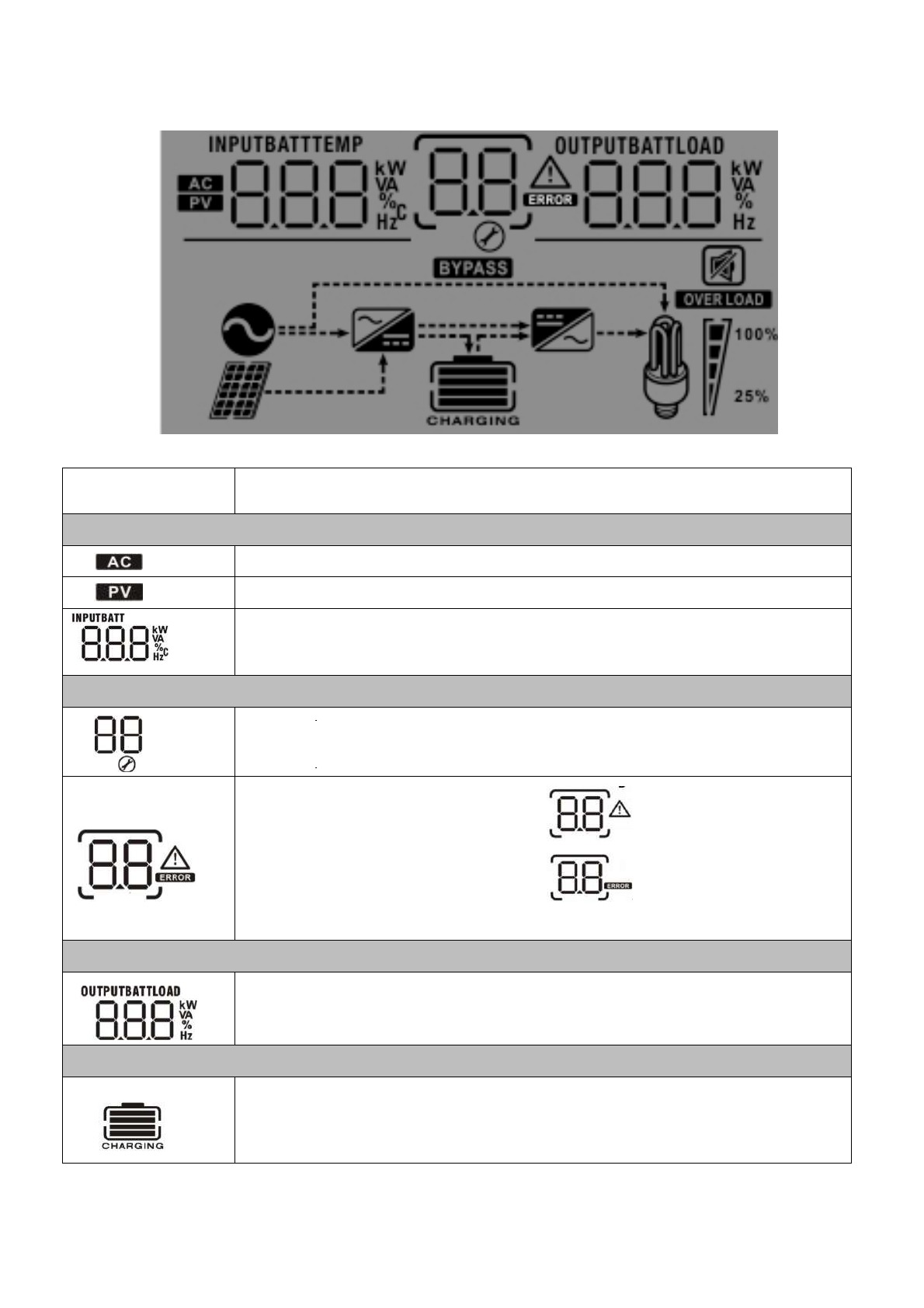
5.3 LCD Display Icons
Icon
Function
description
Input Source Information
Indicates the AC input.
Indicates the PV input
Indicate input voltage, input frequency, PV voltage, charger current, battery
voltage.
Configuration Program and Fault Information
Indicates the setting programs.
Indicates the warning and fault codes.
Warning: flashing with warning code.
Fault: lighting with fault code
Output Information
Indicate output voltage, output frequency, load percent, load in VA, load in
Watt and discharging current.
Battery Information
Indicates battery level by 0-24%, 25-49%, 50-74% and 75-100% in battery mode and
charging status in line mode.
10
In AC mode, it will present battery charging status.
Status Battery voltage LCD Display
Constant
Current mode /
Constant
Voltage mode
<2V/cell 4 bars will
f
lash in tu
r
ns.
2 ~ 2.083V/cell Bottom bar will be on and the other three bars will flash in
turns.
2.083 ~ 2.167V/cell Bottom two bars will be on and the other two bars will flash
in tu
r
ns.
> 2.167 V/cell Bottom three bars will be on and the top bar will flash.
Floating mode. Batteries are fully charged. 4 bars will be on.
In battery mode, it will present battery capacity.
Load Percentage Battery Voltage LCD Display
Load >50%
< 1.85V/cell
1.85V/cell ~ 1.933V/cell
1.933V/cell ~ 2.017V/cell
> 2.017V/cell
Load < 50%
< 1.892V/cell
1.892V/cell ~ 1.975V/cell
1.975V/cell ~ 2.058V/cell
> 2.058V/cell
Load Information
Indicates overload.
Indicates the load level by 0-24%, 25-49%, 50-74% and 75-100%.
0%~24% 25%~49% 50%~74% 75%~100%
Mode Operation Information
Indicates unit connects to the mains.
Indicates unit connects to the PV panel.
Indicates load is supplied by utility power.
Indicates the utility charger circuit is working.
Indicates the DC/AC inverter circuit is working.
Mute Operation
Indicates unit alarm is disabled.

11
5.4 LCD Setting
After pressing and holding ENTER button for 3 seconds, the unit will enter setting mode. Press “UP” or
“DOWN” button to select setting programs. And then, press “ENTER” button to confirm the selection or
ESC button to exit.
Note:All settings must be modified in battery mode and must be rebooted to be valid.
Program Description Selectable option
00
Exit setting mode
Escape
01
Output source priority:
To configure load power
source priority
Utility first (default)
Utility will provide power to the
loads as first priority.
Solar and battery energy will
provide power to the loads only
when utility power is not available.
Solar first
Solar energy provides power to
the loads as first priority.
If solar energy is not sufficient to
power all connected loads, battery
energy will supply power the loads
at the same time.
Utility provides power to the loads
only when any one condition
happens:
- Solar energy is not available
- Battery voltage drops to
low-level warning voltage or the
setting point in program 12.
Battery first
Solar energy provides power to
the loads as first priority.
If solar energy is not sufficient to
power all connected loads, battery
energy will supply power to the
loads at the same time.
Utility provides power to the loads
only when battery voltage drops
to either low-level warning voltage
or the setting point in program 12.
02
Maximum charging current:
To configure total charging
current for solar and utility
chargers.
(Max. charging current =
utility charging current +
solar charging current)
Default:60A
setting range is 10 A to100 A, the
increment or decrement is 10A pe
r
click.

12
03
AC input voltage range
Appliances (default) If selected, acceptable AC input
voltage range will be within
90-280VAC.
UPS If selected, acceptable AC input
voltage range will be within
170-280VAC.
05
Battery type
AGM (default) Flooded
User-Defined If “User-Defined” is selected,
battery charge voltage can be set
up in program 26, 27.
06
Auto restart when overload
occurs
Restart disable (default) Restart enable
07
Auto restart when over
temperature occurs
Restart disable (default) Restart enable
09
Output frequency
50Hz (default) 60Hz
10
Output voltage
220V 230V (default)
240V
11
Maximum utility charging
current
Note: If setting value in
program 02 is smaller than
that in program in 11, the
inverter will apply charging
current from program 02 for
utility charger.
Default:30A
setting range is 2 A,10A to 80 A,
the increment or decrement is 10A
per click.
12
Setting voltage point back to
utility source when selecting
“SBU priority” or “Solar first”
in program 01.
Available options in 3.5KW model:
23.0V(default)
Setting voltage point back
24V model:(default 23.0Vdc)
setting range :22.0V to 25.5V
setting increase or decrease of
0.5V.
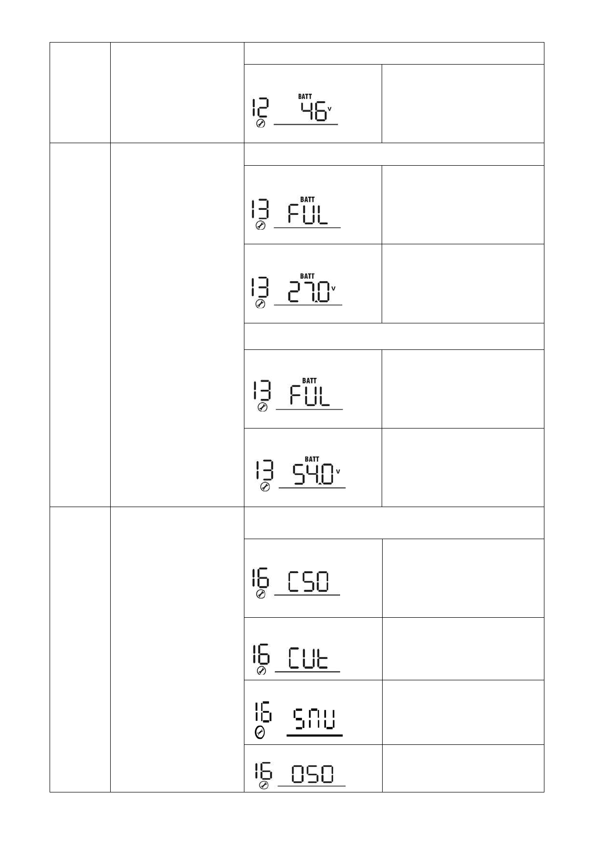
13
12
Setting voltage point back to
utility source when selecting
“SBU priority” or “Solar first”
in program 01.
Available options in 5.5KW model:
46.0V(default)
Setting voltage point back
48V model:(default 46.0Vdc)
setting range :44.0V to 51V
setting increase or decrease of
1.0V.
13
Setting voltage point back to
battery mode when selecting
“
SBU priority” or “Solar first”
in program 01.
A
vailable options in 3.5KW model:
Battery fully charged
27.0V (default)
Setting voltage point back
24V model:(default 46.0Vdc)
setting range :24.0V to 29.0V
setting increase or decrease of
0.5V.
A
vailable options in 5.5KW model:
Battery fully charged
54.0V (default)
Setting voltage point back
48V model:(default 46.0Vdc)
setting range :48.0V to 58.0V
setting increase or decrease of
1.0V.
16
Charger source priority:
To configure charger
source priority
If this inverter/charger is working in Line, Standby or Fault mode,
charger source can be programmed as below:
Utility first Utility will charge battery as first
priority.
Solar energy will charge battery
only when utility power is not
available.
Solar first Solar energy will charge battery as
first priority.
Utility will charge battery only
when solar energy is not available.
Solar and Utility (default)
Solar energy and utility will char
g
e
battery at the same time.
Only Solar Solar energy will be the only
charger source no matter utility is
available or not.
14
16
Charger source priority:
To configure charger
source priority
If this inverter/charger is working in Battery mode, only solar
energy can charge battery. Solar energy will charge battery if it's
available and sufficient.
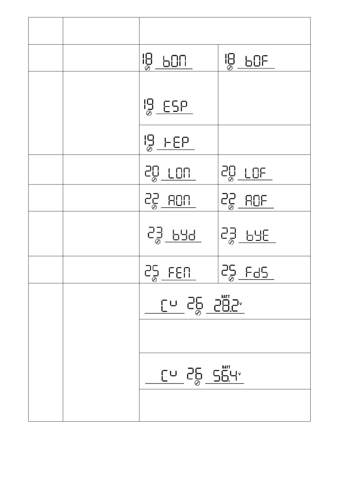
18
Alarm control
Alarm on (default) Alarm off
19
Auto return to default
display screen
Return to default display
screen (default)
If selected, no matter how users
switch display screen, it will
automatically return to default
display screen (Input voltage
/output voltage) after no button is
pressed for 1 minute.
Stay at latest screen If selected, the display screen will
stay at latest screen user finally
switches.
20
Backlight control
Backlight on (default) Backlight off
22
Beeps while primary source
is interrupted
Alarm on (default) Alarm off
23
Overload bypass:
When enabled, the unit will
transfer to line mode if
overload occurs in battery
mode.
Bypass disable (default) Bypass enable
25
Record Fault code
Record enable (default) Record disable
26
Bulk charging voltage
(C.V voltage)
3.5K default setting: 28.2V
If self-defined is selected in program 5, this program can be set
up. Setting range is from 25.0V to 31.5V Increment of each click
is 0.1V.
5.5K default setting: 56.4V
If self-defined is selected in program 5, this program can be set
up. Setting range is from 48.0V to 61.0V Increment of each click
is 0.1V.
15
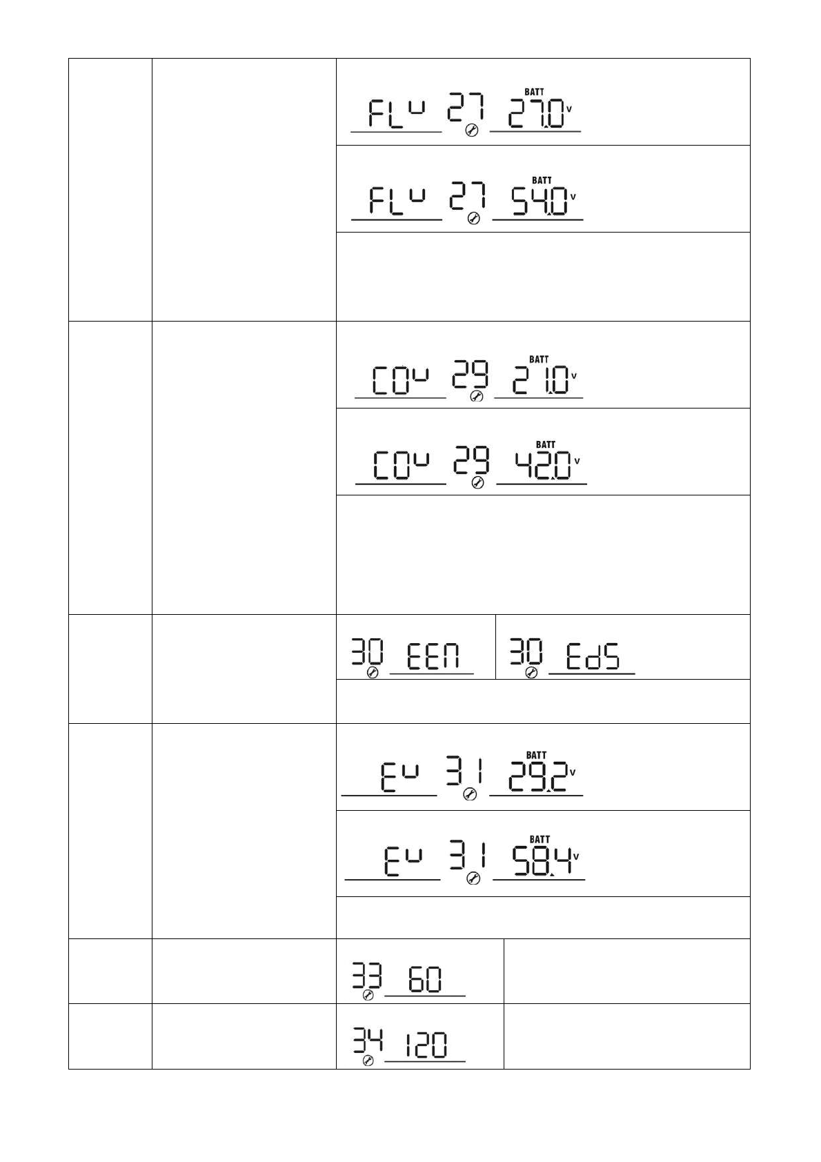
27
Floating charging voltage
3.5K default setting: 27.0V
5.5K default setting: 54.0V
If self-defined is selected in program 5, this program can be set
up. Setting range is from 25.0V to 31.5V for 3.5KVA model and
48.0V to 61.0V for 5.5KVA model. Increment of each click is
0.1V.
29
Low DC cut-off voltage
3.5K default setting: 21.0V
5.5K default setting: 42.0V
If self-defined is selected in program 5, this program can be set
up. Setting range is from 21.0V to 24.0V for 3.5KVA model and
42.0V to 48.0V for 5.5KVA model. Increment of each click is 0.1V.
Low DC cut-off voltage will be fixed to setting value no matter
what percentage of load is connected.
30
Battery equalization
Battery equalization Battery equalization disable (default)
If “Flooded” or “User-Defined” is selected in program 05, this
program can be set up.
31
Battery equalization voltage
3.5KVA default setting: 29.2V
5.5KVA default setting: 58.4V
Setting range is from 25.0V to 31.5V for 3.5KVA model and 48.0V
to 61.0V for 5.5KVA model. Increment of each click is 0.1V.
33
Battery equalized time 60min (default) Setting range is from 5min to 900min.
Increment of each click is 5min.
34
Battery equalized timeout 120min (default) Setting range is from 5min to 900 min.
Increment of each click is 5 min.

16
35
Equalization interval 30days (default) Setting range is from 0 to 90 days.
Increment of each click is 1 day
36 Equalization activated
immediately
Enable Disable (default)
If equalization function is enabled in program 30, this program can
be set up. If “Enable” is selected in this program, it’s to activate
battery equalization immediately and LCD main page will
shows
“ ”.
If “Disable” is selected, it will cancel equalization function
until next activated equalization time arrives based on program 35
setting. At this time, “ ”will not be shown in LCD main page.
40 Discharge limited current
OFF: default ;
discharge current limited disable
setting range :10A to 200A
setting increase or decrease of 5A.
NOTE:1. if you work in “PV priority
mode” or “SBU priority mode”, when
the loads is greater than the current
limiting point, it will automatically
switch to utility mode.
2.if it only works in battery mode,when
the load is greater than the current
limiting point,the inverter will shut
down immediately.
41 Lithium battery discharge
stop
Default:6%
1.When the battery capacity of the
lithium battery is lower than the set
point, the inverter stops discharging
and output will be turned off.
setting range :1% to 60%
setting increase or decrease of 1%.
2.when the communication
connection between the lithium
battery and the inverter is
normal,”USER” will be displayed next
to the battery icon on ten display
screen
42 Lithium battery charge stop
Default:96%
1.When the battery capacity of the
lithium battery is higher than the set
point, the inverter stops charging
setting range :60% to 100%
setting increase or decrease of 1%.
2.when the communication
connection between the lithium
battery and the inverter is
normal,”USER” will be displayed next
to the battery icon on ten display
screen

17
5.5 Fault Reference Code
Fault Code Fault Event
01 Fan is locked when inverter is off.
02 Over temperature
03 Battery voltage is too high
04 Battery voltage is too low
05 Output short circuited or over temperature is detected by internal converter
components.
06 Output voltage is too high.
07 Overload time out
08 Bus voltage is too high
09 Bus soft start failed
51 Over current or surge
52 Bus voltage is too low
53 Inverter soft start failed
55 Over DC voltage in AC output
57 Current sensor failed
58 Output voltage is too low
59 PV voltage is over limitation

18
5.6 Warning Indicator
Warning Code Warning Event
01 Fan is locked when inverter is on.
02 Over temperature
03 Battery is over-charged
04 Low battery
07 Overload
10 Output power derating
15 PV energy is low
16 High AC input (>280VAC) during BUS soft start
Battery equalization
Battery is not connected
This manual suits for next models
2
Table of contents
Other CNBOU Inverter manuals

Popular Inverter manuals by other brands


Samlexpower
Samlexpower PST-120-12 owner's manual

Deye
Deye SUN-3.6K-G user manual

Lenze
Lenze i510 Series operating instructions

Endress
Endress ESE Series Use and maintenance manual

Solplanet
Solplanet ASW 3-6K S G2 Series Quick installation guide

Victron energy
Victron energy MultiPlus 12/5000/200-100 230V user manual