CNC Hager Impressivo User manual

1
Impressivo
All rights reserved. Reproduction and commercial use of these instructions are not allowed.
For consequential damages that may result from the operation of our model aircraft,
will assume no liability. Changes of parts or materials shall be carried out at its own discretion.
The information referred to in this assembly guide accessories, radio gear and the drive are
only recommendations.
Instructions
Than you for the purchase of this product and congratulations, you've chosen
a quality product made in Germany out of the house CNC Hager.
Please read these instructions carefully before construction and proceed with building step by step.
General Information:
The Impressivo a Funmodell in wood construction in conjunction
with carbon fiber. It boasts a radical new loo , CNC machined parts and large range
of speeds which can be flown both slow and very fast without losing in indliness and
safe handling.
The wing rib is created in design and equipped with high Carbon Pipes.
A double hull bottom to ensure a clean battery cables and a pleasant change.
The instructions in this rudder deflections are given a basic setting for the first flights.
This can also be easily adapted to its own fiscal habits.
Construction: ribs, sides, ribs and ridges are dovetailed with each other and thus ma e it
much easier to ensure the development of the model.
For sufficient stability at high speeds The large-sized Carbon Spars in the wings.
The test models were covered with Oracover.
Tested Drive and RC:
Motor : MEGA 16 / 15 / 3
Battery : 3S Ko am 2100mah 30C
Regulator : 40A
Prop : 4,7 x 4,7 CAM Speed
Receiver : Schulze Delta 535
Servo : Graupner DES 427 BB Digital
2
A
B
C
D
R1
R2
R3
R24
R1
R1
R4
R5
R6
R7

3
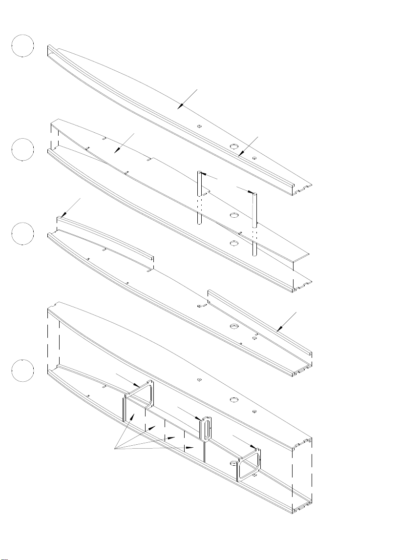
- In building the fuselage side panels ensure that occur right
and left halves.
- The lower Square bar R1 (balsa bar 4x4) flush
along the outer edge on the side panel stuc R2,
ensure to watch on left and right halves.
- Doubler R3, and adapt the body with viscous
superglue to the R2 side part glue.
(The carbon pipes ta e R24 to help)
- The remaining torso straps R1 on the side panel R2 stic .
- The side panels using the Carbon pipes together R24 and
the fuselage contour sanding down slightly.
- To facilitate the insertion of the ribs, you should buff the edges.
So this way the body R3 is not damaged.
- The fuselage with the ribs R4, R5, R6 and the previously
composite floor part R7 stic them together.
- 1mm holes of R5 and R6 show up (cover).
- Focus on a level surface.
The bottom part of first serves to the exact angle of
Bul head to reach R4, so the trun is the bonding
not oblique warped.
- Later, after completion of the trun of the soil at the
perforated line is disconnected in order to move
the cable forward in the fuselage nose to.
- Joists and base together.
A - C
D
Hull Structure
4
A
B
C
D
R8
R10
R9
R11
R12
R13
R14
R15

5
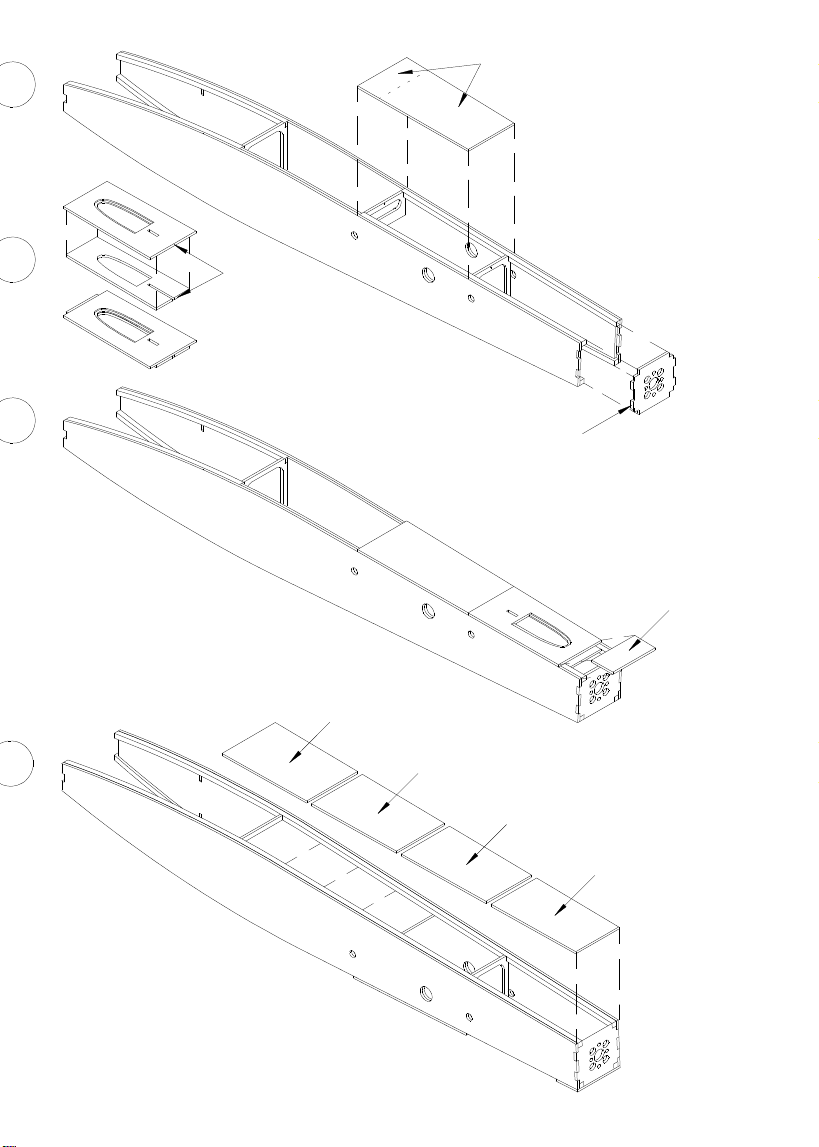
- Cover of both R8 (Balsa 2mm) together with the
Hull clog, the middle between the ribs R5 and R6.
(ensure that the lid is stuc )
- Motor frame paste R9.
- Bottom parts R12 - R15 (Balsa 2mm) in order from
stic bac to front.
- Beginning with R12 ma e sure that R12 is sitting,
so that the angular deviation to the front is not too large.
A
D
- Cover composed of both R10 (Balsa 2mm) (Figure B).
This cover is required for step C.
- Cover R11 use R10 cover stic .
B
C
6
A B
C
D
R19
R18
R20
R16
R17
R21
R22
R23

7
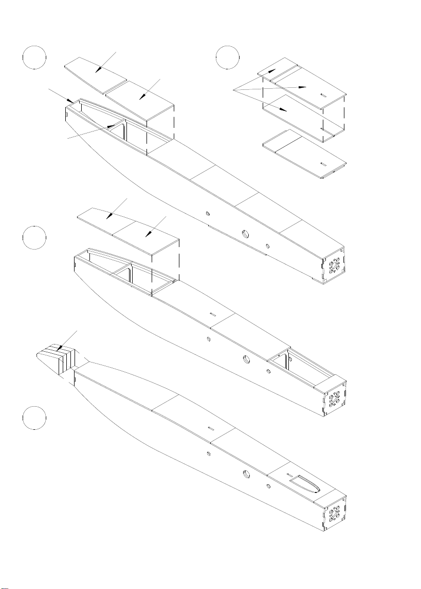
- Bul head using R16 and R17 is bonded with only R17 in order to
ma e any correction to be in default.
- The trun to one side and the height of the Building board
Bul head R17 measure. The hull to the other side turn
and repeat the measurement. The hull witch might have occurred
Differences corrected accordingly, leading to the prevention of
fuselage nose is bent.
- The bottom parts of R18 and R19, ta ing into account that no
Delay or a twist in the fuselage stic ing occurs.
- R16 and R17 bonded finished.
- Together cover all of R20 (Figure B).
This cover is required for step C.
- The remainder covers R21 and R22 with the help of
R20 clog. With the R20 the correct distance to the first
R21 cover are determined.
R21 thereafter stic ing straight and centered.
- The nose bloc from all the R23 (Balsa 8mm) together.
- Stic to the nose bloc centered on the trun .
(Here note the correct shape of the nose in the side view.)
- Fully inclusive of both the trun lid, witch you previously
where appropriate, with two very small drops of Superglue
can loc on the trun , where they should not hold by itself.
- The complete contour, and the fuselage nose strongly rounded.
This is very important because it is an important component of
overall appearance is.
See section B - B.
A
B
C
D

8
A
B
Warning: right and left surface!
F1
F2
F3
F4
F5
F6
F9
F9

9
- Next steps Please read carefully and completely,
because they contain very important details for proper construction.
- Both halves are simultaneously to built up.
- The root rib (consisting of F1, F2 and F3) using
the aluminum tubes F9 together.
Procedure:
- The somewhat deburring aluminum tubes F9 in the appropriate
Mounting holes (see map or picture threading).
- Test ways F1 - composed F3 succession.
If everything fits, use the superglue and repeat.
When bonding ensure that there is no glue on the aluminum tubes,
they are used initially only for mounting.
Also no glue allowed in the area where later
Nose and end strips is inserted.
Since it adversely affect the fit.
- Note: The mounting holes of F1 - F3 are necessary to ensure
the correct offset of the "receiving holes for the aluminum tube arises.
Only then later formed the right slant of the root rib
to the fuselage.
Attention:
The following construction phase has a right and left side.
- The carrier ribs F4, F5 and F6 eys together. Here do the same
as in the root ribs F1 - F3.
(Please watch right and left.)
- Note: Do not glue to the aluminum tube to raise the aspect ratio.
The area of vertical tail inta e should remain without adhesive!
A
B
Building wings

10
A
B
C
D
Warning: right and left surface!
Linkage choose up or down!
F16
F17
F10 F11 F12 F13 F14 F15
F9
F8
F1-3 F7 F4-6

11
- The following steps are initially set only!
- The inner surface stic together gently.
Consisting of F1 - F3, F4 - F6, F7, F8 and F9.
(Please watch right and a left wing.)
Both tailboom F4 - F6 to loo up.
The aluminum insert tubes F9.
The inclination of the ribs again and again compare with the plan.
- The wing with F10 - F15 by plugging together expand.
For F10 - F11 can be decided whether the rudder top
or to be articulated to the bottom.
(see Section A - A on the plan)
The test models were always articulated below.
- The bar F16 gently and evenly from
stuc inside to the outside of the ribs.
- Chamfer on both ends of Carbon pipe F17 somewhat obliquely.
Note: Unfortunately, it is technically still part of the supplier
possible to completely get coal straight pipes, since they also
subject to certain tolerances. Please enter pipe before installation to
flat surface and roll mar the highest point in the middle.
The mar ed spot has to be installed in the direction of leading edge
rotate. So both surfaces have a slight arc-shaped
to the rear which is not a problem.
- CFK tube F17 carefully and always with
Screw rotating movement rib for rib.
A - D

12
A
B
C
F18
F18
R24
F18
F18
90 degrees
F25
F19
F20
F26
F21
F23/F24
Base

13
- Before the sash is stuc , please ma e a chec .
Defer to the wing spars R24, which earlier in the trun
were inserted. Two equal parts F18 front and rear intermediate
hold.
(See Figure A)
- The wing on a perfectly flat and lay flat surface.
The flat rear F18 and F18, the high forward under the
Leading edge F8 or F16 set the bar. (Figure B)
- Aluminum Pipes F9 must now be flush with F6.
- If everything aligned and warp to the corresponding
Ma e a complaint is something that can completely wings
are glued together with thin superglue.
- Remove from the wing and rebonding Building board remaining
places which could not be bonded.
- Always stuc on both sides.
- F19 and F20 (plywood using 1.5 mm) according to plan.
- F22 and F21 cover update it on ribs apart.
(Balsa 2mm)
- Both F21 with 4mm offset with the help of F22
stic to F19. Not stic servo cover F22! (Section A - A)
- F23 and F24 (Balsa 2mm) to use and glue.
- Trumpet F25 stic .
- F1 root rib and rib F15 final sanding flush.
- Wingtips F26 fix and glue.
(Holes can be used as an aid)
A - C

14
A
C
D
Not so!
But so!
B
F29
F27
F28
1.5 mm spacing

15
- The ribs in the front profile during sanding down gently.
Wingtips not yet rounded.
It will be sanded together with the aileron.
- The leading edge F8 carefully rounded.
- The bar F16 and the protruding rib F2 and F5 in
View History slur.
- Please be careful not to grind the ribs too.
- The end strip F27 adjust.
The rudder use F29 as a template to
to control the correct position of the end strip.
The end strip must lie symmetrically to the course profile,
otherwise, a rolling motion in flight is created (see Figure B).
- The two sides compared.
- The end strip F27 easily with super glue and Small dots
both surfaces to compare with each other again, before this
will be bonded with thin superglue.
- The ailerons on the wing F28 to create. For the optimal
Distance oar horn F30, the F27 can be resolved.
- The rudder with scotch tape to fix.
The oar loc inside with F27.
- The wingtips F26 including rowing F28-finished and
Wing final grinding.
D
C
B
A
16
Rounded contour
Rounded contour
R25
Steel wire 0.8 mm
Servo side Rowing page
Steel wire 0.8 mm
A
C
B
F31

17
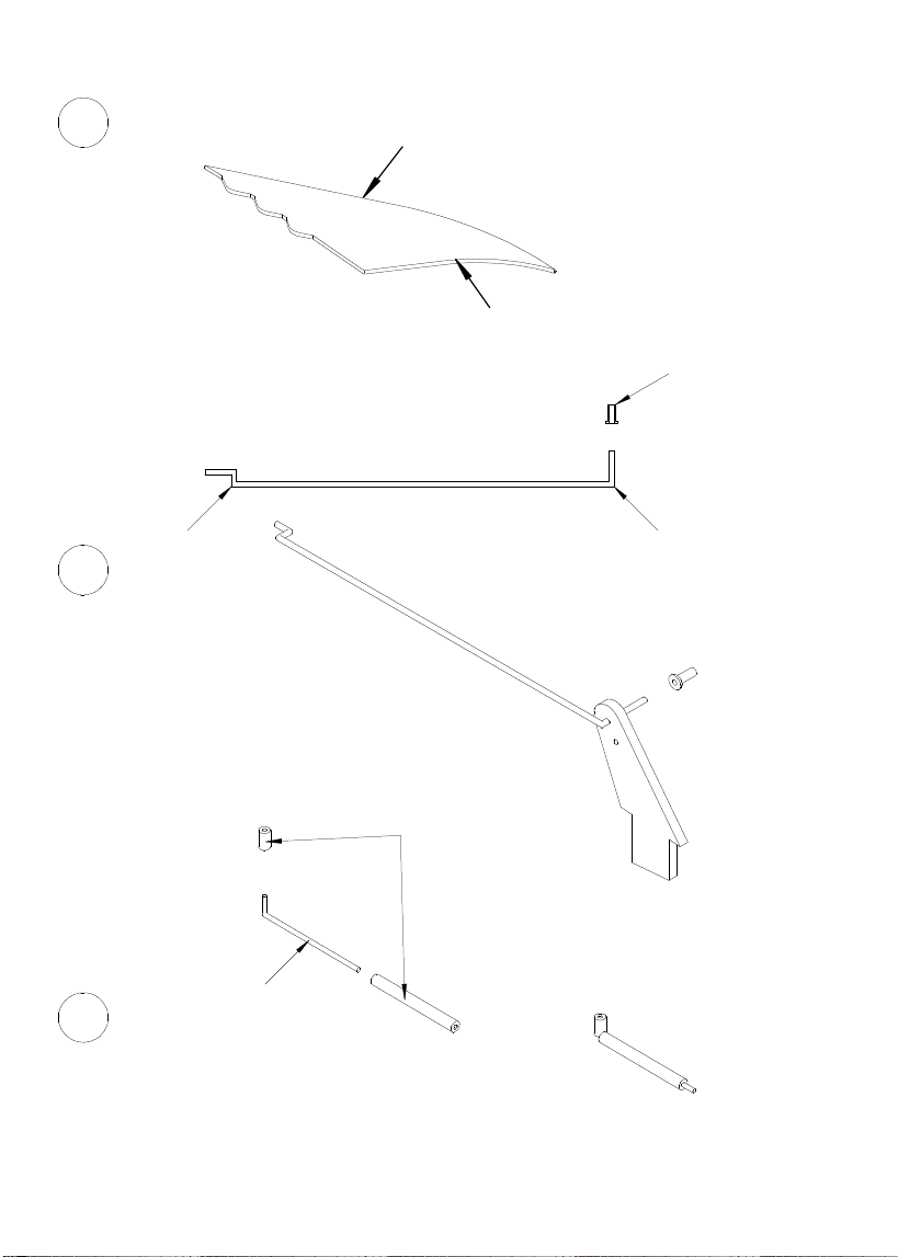
- The rudders F29 front and rear round.
- The model fit test basis.
Please ma e any needed corrections arising.
- Set in servos after chec ing power steering, (middle set)
use the mounting screws grind on the top, so that no damage
Covering is.
- The servo may be adapted to cover F22 servo.
- The lin age of rowing lin age steel wire 0.8 mm
. produce
To attach the helm again with adhesive tape and oar horn F30
einstec en.
How can a test basis, the power to be moved or adjusted.
(see picture or diagram)
- The closure of the two hoo s lid R25 and
Steel wire 0.8 mm produced (see picture or diagram).
Completion shell
C
B
A
18
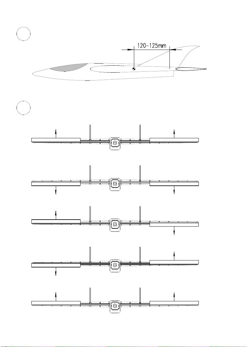
Elevator (top)
Elevator (down)
Aileron (left)
Aileron (right)
Start position (top)
5 mm
5 mm
5 mm5 mm
5 mm
5 mm
5 mm
5 mm
1 mm1 mm
Center of Gravity
Rudder setting: (rear view)
A
B
Slow 1-2 Sec.
Expo ca. 50%
Expo ca. 50%

19
Completion of the Model
- The extension leads 50 cm (included in delivery) in the wings
do not draw.
- If everything fits, the model can be covered at its own discretion.
(All test models were covered with Oracover.)
- The oars should become ironed, because scotch tape could
free itself with high speeds.
- The foil in the mortising of the wings and side tail units remove carefully
(wood under it not slit!).
- The foil in the body in the area of the root rib something remove, so that a
Splice originates for the next wedding (wings push open and draw with
a pencil the rib contour).
- Carbon tubes R24 in the hull insert and communicate.
- Pipes clog with trun .
- Slow enough glue (Epoxy, white glue, resin)
enter into the aluminum tubes.
- Thic superglue in the root rib area apply.
- Hull put on flat surface and threading both wings.
- Thread the cable into the trun and put off both wings evenly.
Ensure that any different angle formed by
eventual game in the pipes.
- Glue wings to the fuselage.
- Rudders insert, align and glue.
- Air inta e R26 paste.
- Fasteners at the paste into the lid.
- RC Engines and install (see map).
- Determine the exact focus (see Figure A and Plan).
- Rudder settings to ma e recommendation (See Figure B).
- Antenna installation, in its discretion.
Assembly

20
Final control and Test-Flight
The surfaces please again for delays examine and chec the oars for right function.
Start : - Accumulators loaded?
- Flight accumulator against slipping secure?
- Transmitters switch on?
- Flight accumulator connect
- Main focus again chec
- Start position on top
- Engine on half gas switch on and just throw.
- After the throwing the model should finish a
steady straight flight slightly rising.
If necessary something must be posttrimmed.
- If everything fits, start position switch off.
Now model should lower the nose and become quic er.
- The given Settings can be adapted at its own discretion.
A lot of fun with the construction and aviation
wishes your CNC Hager Team.
for more informations:
cnc.hager@googlemail.com www.cnchager.jimdo.com
Table of contents
Other CNC Hager Toy manuals


Popular Toy manuals by other brands


POLA G
POLA G 331725 manual

Little Tikes
Little Tikes LITTLE BABY BUM TWINKLE'S SINGING SOOTHER quick start guide

Brookstone
Brookstone Rover Land & Sea user manual

Viessmann
Viessmann 26254 manual

Mattel
Mattel PIXAR L9833-0920 instructions

Harbor Freight Tools
Harbor Freight Tools 95641 Assembly and operation instructions