CNC Hager Impala Instruction Manual

1
Congratulations on your purchase of the Impala, and many thanks!
You are now the owner of a high-quality product “Made in ermany” by the CNC Hager company.
Please read right through these building instructions before starting construction, and follow the
sequence carefully when building.
eneral information on the model :
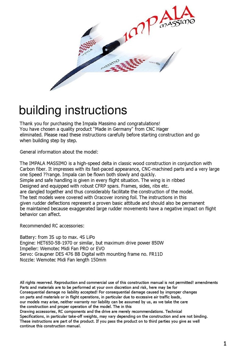
The IMPALA is a high-speed delta of orthodox all-wood construction, with some carbon fibre parts.
Its outstanding features are its sleek appearance, CNC-cut parts and its very broad speed range:
the Impala is a stable flyer at both low and high speed, and it offers straightforward, reliable
handling in every aspect of flight. The wings are of built-up construction, featuring strong CFRP
spars. The control surface travels stated in these instructions have been tested by us, and are
safe basic settings for your initial flights. Naturally you are free to fine-tune them to suit your
personal preference.
Construction :
Formers, fuselage sides, ribs etc. are of interlocking design, as this makes the model much easier
to build. The CFRP wing spars provide adequate airframe strength at high speeds.
The test models were finished in Oracover iron-on film.
RC equipment :
Motor :
see www.hoelleinshop.com
EDF unit :
Wemotec Mini Fan PRO
Servos :
raupner DES 427 BB digital
Building Instructions
All rights reserved. Copying and commercial exploitation of these building instructions is prohibited. Be aware that
any modifications to parts and materials are at the builder’s discretion and risk. We accept no liability for consequent
damage resulting from unsuitable modifications to parts and materials, or from inappropriate flying, especially where
our models are subjected to excessive flight loads. Such consequences are not covered by the guarantee, and we
accept no liability since we are unable to monitor the quality of construction and the methods you use to operate the
model. The accessories, RC components and power system stated on the plan are only our recommendation.
Technical information, especially in respect of flying weight, may vary according to your construction methods, and
cannot be guaranteed. These building instructions are an integral part of the product. If you ever transfer the model
to a third party please be sure to pass on the instructions to the new owner

1
2
3
4
R1
R2
R3
R33
R1
R1
R4
R5
R6
R7
2
Caution: take care to produce a handed
pair of fuselage sides (left and right)!
R9
R8
5

- When preparing the fuselage sides be sure to produce a handed pair, i.e.
one R.H. and one L.H. side. Each step should be repeated with the
second fuselage side.
- lue the lower fuselage longeron R1 (4 x 4 mm balsa strip) to the fuselage
side R2, flush with the outside edge.
- Fit the formers R4, R5 and R6 and the bottom panel R7 in one fuselage side.
! Lightly sand the former tabs if they are a tight fit, to avoid damage to the
fuselage doublers R3.
- Lay this assembly on a flat surface, and fit the second fuselage side on top.
The bottom panel R7 helps to align the formers correctly.
- Check that the fuselage sides, formers and bottom are straight and undistorted,
then glue the parts together.
4
Fuselage construction
1
- Offer up the fuselage doubler R3 and trim it to fit if necessary before laying
it on the fuselage side R2. Position it carefully, using the CFRP tubes R33
or a 5.9 mm Ø drill to aid alignment, and glue it in place using high-viscosity
(thick) cyano adhesive.
2
- lue the remaining fuselage longerons R1 to the fuselage side.
- Lay the fuselage sides together, aligning them with the CFRP tubes R33,
and lightly sand the outside shape.
3
3
- lue together the two towhook plates R8 (2.0 mm light ply) before gluing
them to the underside of the bottom panel R7.
- Fit a large washer on an M4 screw, and use it to pull the captive nut R9
into the bottom panel R7 and the towhook plates R8. Press it firmly into
place and glue it securely.
5

6
7
8
R10
R18
R26
R25
R12
R13
R11
R14
R15
R16
R17
R23
R22
R1
R20
R14a
R14b
4
R21
R19
(R24a)
(R24b)

- lue together the two parts R10 (2.0 mm balsa) to form the rear top fuselage
deck. Weight the fuselage down on a flat surface before gluing the deck in place.
- Fit the tail former R11, and glue it in place.
- Sand back any projecting edge of the top deck R10 so that it ends flush
with the former R6.
- lue the in-fill block R12 (8.0 mm balsa) in place, followed by part R13
(2.0 mm balsa).
- Prepare the two removable hatches by gluing together parts R14a + b and
R24a + b (2.0 mm balsa). These hatches are required later to help you position
particular components correctly.
- Fit the hatch R14 against the former R6, then glue the bottom panel R15 in
place, keeping it central. Take care not to glue the hatch R14 in place at the
same time.
- lue the two bottom panels R16 and R17 to the fuselage as shown.
- lue the rear bottom panel R18 in place, clamping two pieces of paper
between the hatch and R18; the paper is approximately the thickness of the
covering film, and helps to prevent the hatch jamming when covering is complete.
- lue the doubler R19 (0.6 mm plywood) to the inside of R18.
6
7
- Fit the formers R20 and R21 between the fuselage sides, but only glue R21 in place
at this stage; this makes it easier to correct any distortions which may become
apparent later.
- Lay the fuselage on one side, and measure the height of the former R21 above the
building board.
- Turn the fuselage onto the other side, and measure the height again.
- If there is a difference between the dimensions, carry out any corrections required.
- lue the bottom panels R22 and R23 to the fuselage, taking care to avoid warps or
twists in the structure.
- The formers R20 and R21 can now be glued in place permanently.
- If the former R4 tends to bend under the pressure from the fuselage sides, add a
stiffener to reinforce it; this can be cut from the R1 material (4 x 4 mm balsa strip).
- lue the remaining top decks R25 and R26 in place using the battery hatch as a
positioning aid. Use the same procedure as described for the rear hatch R14.
8
5

9
10
6
11
Mini Fan Pro
R29a
R30a
R31a
R29b R29b
R30b
R31bR31b
R30b
R28a
R27
R28b
These radii should be identical!
e.g. spirit level or similar
Bottle
90°
Up to 1.5° acceptable

- Assemble the noseblock from all the parts R27 (8.0 mm balsa) before gluing
the block to the fuselage, correctly centred.
! Note the shape of the nose as shown in the side elevation.
- Assemble the tail block from all the parts R29a + b (12.0 mm balsa) before
gluing the block to the tail end of the fuselage, correctly centred.
- The concave radius of the tail block should now be sanded to follow the
radius of the former R11.
! Use abrasive paper wrapped round a bottle or can for this.
! Take care not to sand or modify the support surface for the fan unit.
9
7
- Temporarily attach the two fuselage hatches with two very small drops of cyano
(unless they stay in place by themselves) before sanding the whole fuselage smooth.
- The whole of the outside of the fuselage and tail block should be sanded to the
profiles shown in the cross-sections on the plan.
! In the area between cross-sections E and F the concave radius in the fuselage top
deck must match the inlet lip of the fan unit, to produce a smooth transition to the
fan unit at section F.
- Sand the fan shroud assembly to final shape before gluing it to the fuselage, taking
care to keep it central and straight.
! The fan unit must be aligned at 90° to the wing section (airfoil).
! It is essential to avoid a negative angle (thrustline) at this point. It is better if the
front part of the fan shroud dips slightly into the fuselage (positive thrustline,
max. 1.5°).
- Use abrasive paper wrapped round a bottle to sand back the air intake area of part
R12 (sections E - F) to produce a completely smooth transition.
! The diameter of the bottle must be the same as the inside diameter of the fan unit
(see Fig. 10 and sections A - ).
11
- lue together parts R29a + b, R30 a + b and R31 a + b (1.5 mm balsa) to
produce the three shroud panels as shown, and sand the joint surfaces
carefully on both sides.
- Carefully wrap the shroud panels R29 and R30 round the fan unit “dry” (no glue),
and tape them in place.
! It is a good idea to moisten the wood to ensure that it will bend without breaking.
- Start this procedure with the bottom of R29, curving it upwards until the two ends
touch. You may need to trim the ends according to the thickness of the wood.
- Fit R31 on the inside to produce a smooth transition.
! It is important that all the curved shroud panels align correctly at the bottom and
the front, and end flush with each other.
- When you are confident that all the parts fit correctly, repeat the procedure,
gluing the parts together with cyano adhesive.
- Sand the inlet lip and the rear part of the fan shroud to the profiles shown
on the plan.
10

12
13
F1
F2
F3
F4
F5
F6
2 mm Ø steel rod or drill bit
F9
8

- Please read right through the next steps very carefully, as they contain very
important information on the correct method of building the wings. Repeat
each step for the second wing panel.
- The root rib (consisting of F1, F2 and F3) is assembled using two lengths of
2.0 mm Ø steel rod or drill bits to aid alignment before the parts are glued
together.
This is the procedure:
- Assemble parts F1 - F3 in the correct sequence using the steel rods. If
everything fits properly, repeat the procedure using cyano adhesive, but
take care to avoid glue running onto the steel rods. At the same time keep
the glue away from those areas where the leading and trailing edges will
be attached, as this could affect the fit of the parts.
! The alignment holes in F1 - F3 are necessary in order to set the correct
offset of the holes for the aluminium tubes. This ensures that the root ribs
butt up neatly against the fuselage sides.
- Assemble the support ribs F4, F5 and F6, using exactly the same procedure
as described for the root ribs F1 - F3. In this case fit the aluminium tubes F9
through the holes.
! Don’t allow adhesive to run onto the aluminium tubes or the joiners.
12
13
Wing construction
9

14
15
16
Choose your preferred linkage position: top or bottom
Caution: be sure to build one R.H. and one L.H. wing!
F16
F17
F10 F11 F12 F13 F14 F15
F9
F8
F1-3 F7 F4-6
Rubber bands
10

! The following steps should initially be carried out “dry” (no glue)!
- Carefully assemble the inboard section of the wing, consisting of parts F1 - F3,
F4 - F6, F7, F8 and F9.
! De-grease the aluminium tubes F9, and roughen the surface with
abrasive paper.
- Continue the wing structure by fitting the ribs F10 - 15. In the case of F10 -
F11 you can choose whether the linkages to the elevons (control surfaces)
are to be installed above or below the wing (see section H).
! The test models were fitted with bottom linkages, but if you intend launching
by catapult from a grass strip we recommend top linkages.
- Carefully fit the trailing edge strip F16 onto all the ribs, starting from the root
end and working outwards.
- Sand a slight bevel into one end of the carbon fibre spar F17.
! For technical reasons our supplier of carbon tubes is unable to guarantee that
its products are absolutely straight, as they are subject to certain manufacturing
tolerances. Before installing the tube please roll it on a perfectly flat surface,
and mark the highest point in the middle. When installed in the wing, this mark
should face the leading edge; this results in a slight sweepback angle, which
presents no problems.
- Carefully slip the carbon tube spar F17 into the structure, bevelled end first,
rotating it constantly as it moves through one rib after the other.
16
15
14
11

17
18
19
F18
F18
R33
F18
F18
90 degrees
F25
F20
F19
F26
F23
F21 F22
Underside
12

- It is important to check the wings very carefully before gluing the joints.
- Slide both wings onto the joiners R33.
- Locate two identical parts F18 and support the wings on them at the l
eading and trailing edges to check that the wings butt up correctly
against the fuselage; make any minor corrections required.
17
18
19
- Lay the wing on a perfectly flat, straight surface. Place the smaller packing
pieces F18 under the trailing edge F16, and the larger parts F18 under the
leading edge F8 (see Fig. 18).
- The aluminium tubes F9 should now end flush with the rib F6.
- Weight the wings down lightly and check that everything is aligned correctly,
i.e. without warps. Apply low-viscosity (thin) cyano adhesive to all the
accessible joints in the wing structure.
- Remove the wing from the building board and apply glue to those areas
which were previously inaccessible.
! Apply glue to both sides of each joint.
- Install the servo plate F19 and the frame pieces F20 (1.5 mm plywood) as
shown on the plan.
- lue the supports F21 and F22 (2.0 mm balsa) in place as shown on the plan.
- Trim parts F23 and the servo hatch F24 if necessary to match the rib spacing.
- lue both parts F23 to parts F20 with a 4 mm offset, using the servo cover F24
as a guide (see section H).
! Take care not to glue the servo cover F24 in place!
- lue the tube end-plates F25 in place as shown.
- Sand back any projecting material at the root rib F1 and the tip rib F15 to
produce flat surfaces.
- lue the wingtip block F26 centrally to the tip rib F15.
13

20
22
F29
1,5 mm clearance
1,5 mm clearance
14
F27
21
F28

22
21
20
- Trim the root trailing edges F27 to fit the wings, then tack them in place with a
little cyano. Compare both wing panels before finally gluing these parts in place
using thin cyano.
! The trailing edge must continue the wing section accurately (see Fig. 20). It is
very important that the trailing edge should not be set at a negative (down)
angle, as the model would then have a marked pitch-down tendency in the air.
A slight positive (up) angle would be acceptable, as it would produce a form of
reflex airfoil which would increase lift.
! Check that both wings are identical.
- Sand the leading and trailing edges of the wings to follow the airfoil; the leading
edges need to be rounded off well. Sand the root and support ribs smooth
without removing too much material.
- Tack the tip fins F28 to the wingtips F26, checking that the edges are flush all
round.
- Trim the elevons F29 in such a way that there is an even gap about 1.5 mm
wide at both ends.
15
- Lightly sand the wings overall, including the tip fins and elevons. Take care
to produce a neat transition between the tip fins and the wingtips F26.
- The tip fins can be removed again once sanding is complete.

Round off edges
Round off edges
R32
1.0 mm steel rod
23
25
24
16
Servo end Control surface end
1.0 mm steel rod
F31 F32
F30

- Round off the edges of the tip fins F28.
- Assemble the model temporarily, and carry out any minor corrections required.
- Fit output arms on the servos, centre them from the transmitter, and install
them in the wings.
! File off the excess length of the retaining screws on the top surface to avoid
damaging the covering film.
Completing the basic airframe
25
24
23
- Make up the elevon linkages from 1.0 mm Ø steel rod (see Fig. 24 and plan).
Tape the elevons in the neutral position and insert the horns F30. The
position of the servos can now be adjusted accordingly.
- Cut away the servo well covers F24 as required to clear the servos and
linkages.
- Make the sliding latches for the two hatches from part R32 and 1.0 mm steel
rod (see Fig. 25 and plan).
17

Elevator (up)
Elevator (down)
Aileron (left)
Expo approx. 50%
Aileron (right)
Expo approx. 50%
5 mm
5 mm
7 mm7 mm
5 mm
5 mm
5 mm
5 mm
Centre of ravity
Elevon settings: (as seen from the tail)
26
27
18
Measured from the rear face
of the trailing edge. See plan view.

Covering and completing the model
- Thread the 50 cm extension leads (not included) through the wings.
- When you are confident that everything is in place and all the fits are
correct, it is time to cover the airframe using the material of your choice
(all the test models were covered with Oracover).
- The elevons should be attached using the covering film as a hinge, as
adhesive tape could come loose at high airspeeds.
- Remove a little film from the fuselage in the root rib area to create bare
wood for the glued joints with the wings.
- Fit the wings on the fuselage, and mark the outline of the root ribs
using a felt-tip pen.
Final Assembly
- Centre the CFRP tubes R33 in the fuselage and glue them in place.
- Apply an adequate quantity of slow-setting adhesive (UHU hart or epoxy resin)
to the aluminium tubes; not too much, as any excess might be squeezed out.
- Apply high-viscosity (thick) cyano adhesive to the root rib area.
- Place the fuselage on a flat surface, and slide both wings onto the joiner tubes.
- Push both wings into place evenly.
! Check that the angle of incidence of both wings is identical; any play in the
joiner tubes could allow a difference to develop.
- lue the wings to the fuselage.
- Attach the tip fins F28 with a little cyano.
- lue the sliding latches to the finished hatches.
- Screw the towhook R34 into the captive nut, and glue it in place.
- Install the power system and RC equipment as shown on the plan.
- Set the Centre of ravity exactly to the 115 mm position, as shown in Fig. 26
and on the plan.
! Don’t be tempted to move the C further aft than the 115 mm point, as this
could cause a tendency for the model to fall into a flat spin in unfavourable
circumstances.
- Set up the elevon travels as recommended (see Fig. 27).
19

20
Final checks, test-flying
Please examine the wings one last time for warps, and check that the elevons work correctly.
We recommend that you do not fit a tail pipe for the first flight: if you set the tail pipe at the
wrong angle it could have an adverse effect on the flying characteristics.
Please note that we VERY STRON LY recommend launching by catapult.
If you hand-launch the model, it will lose height as it gathers speed, but the airflow over the
control surfaces will initially be close to nil. The result is inadequate control response in the
first few moments, and the model could easily crash.
Experienced, muscular launchers have shown that hand-launching can be successful, but for
normal circumstances we always prefer a catapult launch.
We recommend our new catapult release mechanism, which can also be obtained from the
Himmlischer Hoellein company. This device makes catapult launching child’s play for anyone
- even if you are on your own.
The catapult should consist of 25 - 30m of 7 - 8 mm Ø rubber tubing, attached to about 50m
of tow line.
Launching:
- Batteries (including transmitter battery) fully charged?
- Flight battery securely fixed?
- Switch transmitter on: throttle stick at “Off”.
- Connect the flight battery.
- Check the Centre of ravity one last time.
- Run the motor up to half-speed, and launch it using the catapult.
- Once off the catapult, slowly advance the throttle to full, and at the same time apply gentle
up-elevator. The model should now carry out a steady, straight climb.
! Do not be tempted to apply full throttle abruptly at launch, as the thrustline of the ducted fan
tends to push the model nose-down, especially when airspeed is low.
- Take the model up to height and set the trims so that it flies straight at full throttle.
- If the Centre of ravity is set correctly, and the wings are not warped, the elevons should be
in the neutral position at full throttle.
! If this is not the case, you can adjust the angle of the nozzle slightly to fine-tune the thrustline
(similar to conventional downthrust).
! Never try to cure the problem by adjusting the C (flight battery position)!
- Adjust the recommended elevon travels at your own discretion to suit your personal preference.
Landing:
! Carry out a few “dry runs” before the first landing, to get a feel for the Impala’s very
shallow glide angle.
- Fly a wide, low approach at quarter-throttle and cut the motor early on the final leg,
as the model will glide a very long way even without motor power.
! On the final approach, allow the Impala to bleed off as much speed as possible at a
height of about 30 cm before allowing it to touch down. Landing at too high a speed
can cause the model to bounce into the air uncontrollably, or slide around on the landing strip.
All of us in the CNC Hager Team wish you many hours of pleasure building and flying your Impala.
Further tips and information available at: https://cnc-hagershop.de
https://cnchager.jimdo.com www.facebook.com/cnchager cnc.hager@googlemail.com
Table of contents
Other CNC Hager Toy manuals
Popular Toy manuals by other brands

Beyblade
Beyblade Beytarget instructions
Hasbro
Hasbro TransFormers Energon Quickstrike instructions

Canon
Canon Creative Park Kissing Dolls Pattern manual
Fisher-Price
Fisher-Price CCR38 quick start guide

Robotronics
Robotronics Buzz E. Smoke Alarm & Safety House operating manual
AzurPoly
AzurPoly Bede BD-5J Quick reference guide

roco
roco 42440 manual
Eduard
Eduard Zoom C-47 Skytrain interior S.A. Assembly instructions
TecniToys
TecniToys The Digital System instructions
Tabletop Scenics
Tabletop Scenics Fantasy Bowl Stadium Dice Tower Construction guide

Bontempi
Bontempi 14 3343 instruction manual
Mattel
Mattel JURASSIC WORLD GYC94 instructions
