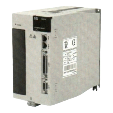
CNCPROM 110ST-M06030 User manual

CNCPROM
Vitkovets CNC
http://cnc.prom.ua/
+380 (096)-665-71-06
+380 (098)-821-25-90
Technical manual: 110ST-M06030, 130ST-M07725,
130ST-M15015, 130ST-M10025

Safety Caution
In order to ensure the safe use of this product, must observe the following safety signs, in order to avoid
warning
Said w rong operation will
trigger dangerous, leading to
mild or moderate personal injury, damage to equipment, and even fire
.
dangerous
Said wrong operation will
trigger dangerous
,
cause injury or death
Said Prohibit operation
Said must operate
After the product arriving, when validation, installation, wiring, operation maintenance,
inspection of the product, the following is one of the important matters must abide by:
●:
Matters needing attention during installation
Warning
It is forbidden to install will happen in the damp and
corrosion environment, a flammable gas environment, and near combustible dust and m etal powder
more environment, or you may get an electric shock and fire.
Matters needing attention during installation
wiring
Warning
◢
The earthing terminal of the servo drive must be grounded, otherwise, will get an electric shock
and fire could occur
◢
It is forbidden to put the output terminal of the servo drive, U, V, W, connected to a three
-
phase power
supply, otherwise, could be injured and fire
◢
damaging to the people and the equipment
It is strictly prohibited to connect the 220v driver to 380 v, 220 v power supply, or you may get an

electric shock and fire
◢
Be sure to tighten power terminal, motor output terminal, otherwise may cause a fire
:
The matters needing attention when running
Dangerous
◢In the
operation , it is forbidden to touch any rotating parts, or you might get hurt
◢In the operation, it is forbidden to
touch electric motor and drive, otherwise you
may burn
Warning
◢
Before operating, must choose the right motor type, otherwise people wil be hurt and the equipment
will be damaged.
◢
Before operating, you must set right parameters and applications that meet the needs of users, or may
be hurt, damage to equipment
◢
Before operating, confirm whether the mechanical may at any time the emergency stop, otherwise, you
might get hurt.
●
:
Maintain the points for attention during the inspection
◢
It is forbidden to touch the inside of the servo drive, or you may get an electric shock
◢
When turn off the power,in the five minutes, do not touch terminals, otherwise, the residual voltage may
cause electric shock
◢
It is forbidden to tear open outfit servo motor, or you may get an electric shock

CATALOGUE
Chapter 1 Product inspection and installation……………………………………………………………………1
1.1 PRODUCT
INSPECTION .......................................................................................................1
1.2 PRODUCT BRAND ................................................................................................................2
1.3 THE FRONT PANEL OF PRODUCT ..................................................................................... 2
1.4 DRIVE TECHNOLOGY SPECIFICATIONS ......................................................................4
1.5 SERVO MOTOR INSTALLATION ..................................................................................... 5
1.6 THE MOTOR DIRECTION OF ROTATION .........................................................................6
1.7
THE KRS
SERIES DRIVE AND MOTOR MODEL ADAPTATION ..............7
CHAPTER 2 WIRING
.........................
8
2.1 THE SYSTEM COMPOSITION AND WIRING
..................................................................
8
2.2 CN1
COMMUNICATION INTERFACE
.............................................................................
11
2.3 CN2
CONTROL INTERFACE
........................................................................................
13
2.4CN3
ENCODER INTERFACE
...................................................................................
18
2.3 THE STANDARD WIRING....................................................................................................
19
CHAPTER 3 PANEL OPERATION
...
21
..............
..............
................................

3.1 PANELS
..........................................................................................................................
21
3.2 MODE
SWITCH
............................................................................................................
21
3.3 MONITORING MODE OPERATION
................................................................................
22
3.4 AUXILIARY MODE OPERATION
...................................................................................
22
3.5 USER PARAMETER MODE OPERATION
................................................................
30
CHAPTER 4FUNCTION PARAMETERS
.............
31
4.1 PARAMETER SETTINGS PANEL
.........................................................................
31
4.2 PARAMETER LIST
........................................................................................................
32
4.3 PARAMETERS
................................................................................................................
44
4.4 PORT FUNCTIONS
....................................................................................................
87
CHAPTER 5
MONITORING PARAMETERS AND
OPERATION ....................................................................... 92
5.1 MONITOR PANEL OPERATION
...................................................................................
92
5.2 MONITOR THE PARAMETER
LIST
...........................................................................
93
CHAPTER 6 ALARM AND PROCESSING
........
94
6.1 ALARM
CLEARANCE
OPERATION
................................................................................
94
6.2 ALARM CONTENT AND COUNTERMEASURE
........................................................
94

CHAPTER 7
MODBUS COMMUNICATION
FUNCTION....................................................................... 100
7.1MMODBUS COMMUNICATION INTRODUCTION
...........................................................
100
7.2 COMMUNICATION PROTOCOL STRUCTURE
...............................................................
101
7.3 COMMONLY USED COMMAND CODE.............................................................................103
7.4 THE SERVO PARAMETERS,
THE STATE INFORMATION COMMUNICATION ADDRESS
............................................................................................................................................
115
THE APPENDIX
..........................................................
116
APPENDIX A
GAIN SWITCH
.......................................................................................
116
APPENDIX B
CONTROL MODE SWITCH
...............................................................
116
APPENDIX C
SERVO DRIVER WORK SEQUENCE
.......................................
120
APPENDIX D
ELECTROMAGNETIC BRAKE
...............................................................
121
APPENDIX E
REGENERATIVE BRAKING
RESISTOR
................................................
122
APPENDIX F
ORIGIN POINT
.......................................................................................
123
APPENDIX G
INTERNAL POSITION CONTROL
.......................................................
131

1
Chapter One products
inspection and installation
1.1Product inspection
This product has made the complete function test before the
leaving the factory,
to prevent the product in
the course of transportation for negligence resulted in the product (s) is not functioning properly. Once
opened, please check the detailed the following matters:
●
check the servo drive and servo motor type with the same whether order model
●
Check the appearance of the servo drive and servo motor whether there is any
damage and scratches phenomenon.
If
there is any damage during the shipment, please
don’t wire power transmission.
●
Check the servo drive and servo motor
if there is any loose parts and other
phenomenon. If there is a loose screw, screw not lock or fall off
●
Check the servo motor rotor shaft can
be
smooth rotation.
The
motor with brake cannot be directly
rotation
If there is
any
fault or unmoral phenomenon, please contact with dealers
immediately

2
1.2ID label
AC
SERVO
DRIVER !
ASDD-30A
AC220V/50-60HZ
30A
1.3The front panel
Model
Voltage
Output Current
Danager
Please install, connection, using as manual
Please don't install or un-install
the driver when it is connected to
the power and cut off the power
within 5 min.

3
1.4 The function of AC servo motor driver .
Five Number LED Screen
Four Number Button
Signal Port
Control Port
Encoder Interface
Ground
Single/Three Phase AC220V Input
Power Output Of Driver
External regenerative braking resistor

4
The input power
Single phase or three phase AC220V
-15~+10%
50/60Hz
environme nt
temper ature
Using:0~55℃Storage: -20℃~80℃
humidity
Below 90% RH No dewing
vibration
Belown0.5G(4.9m/S ),10-60 no continue running
Control mode IGBT PWM sine wave control
Control mode
①
Torque mode (internal or external)
② speed mode (internal or external)
③
Position mode (internal or external)
④
Position/velocity model
⑤
Position/torque model
⑥
Speed/torque model
Control input
servo enables
alarm reset
Forward driving is prohibited
Reverse driving i s prohibited
、
External forward torque
is limited
external
reverse torque is limited
Emergency stop
Zero speed clamp
Internal speed command option 1
Internal speed command option 2
Internal speed command option 3
The internal torque command option 1
The
internal torque command option 2
Control mode switch
Gain switch
Electronic gear molecular option 1
Electronic gear molecular option 2
Instructions for
、
Position deviation to clear
Pulse input is prohibited
Proportional control
The origin return to trigger、
,
,,
,

5
1.5Servo motor installation
1.4.1Installation environment conditions
●
Working environment: 0 ~ and ℃; working environment: less than 80% (no condensation)
●Storage environment temperature: -
℃; Storage environment humidity: 80% of the (no condensation)
●
Vibration: Below 0.5 G
●Well ventilated, less moisture and dust place
The origin return reference point
Internal location option 1
Internal location option
2、
Trigger internal position command
Suspend internal position command
Control the output
Alarm detection
Servo ready
Emergency stop checked out、
Positioning to complete
Speed to reach
Reach the predetermined torque
Zero speed detection
Servo motor current
Electromagnetic brake
、
The origin return to complete 、
Located close to
torque limit、speed limit、
Tracking arrive torque command
The encoder feedback
2500p/r,15 line increment model, differential output
Communication mode
RS-232 OR RS-485
Display and operation
①
five LED display ②Four buttons
Braking way
Through the internal/external braking resistance braking energy
Cooling way
Air cooled (heat transfer film, the strong cold wind fan)
Power range ≤7.5KW
,,
,
,

6
●No corrosive, flash gas, oil and gas, cutting fluid, iron powder and so on environment
●
No moisture and direct sunlight place
1.4.2Installation method
●
Level installation: to avoid liquids such as water, oil from motor wire end into the motor internal, please will cable outlet in
below
●Vertical
installation: if the motor shaft and the installation with reduction unit, must pay attention
to and prevent reducer in mark through the motor shaft into the motor internal
●
The motor shaft out quantity must be thoroughly, if insufficient out to motor sports generates vibration
●Installation and remove the motor, please do not use hammer knock motor, otherwise easy to cause damage to the
motor shaft and encoder
1.6 The motor direction of rotation
Looking from the motor load on the motor shaft and counterclockwise (CCW) for the forward, clockwise (the
CW) as the reverse
(CCW) (CW)
Forward Reverse

7
1.7
The KRS series drive and motor
model adaptation
Motor model
Pn001
Rated
speed
(r/min)
Rated
torque
(N.M)
Rated
power
(W)
KRS
15A
KRS
20A
KRS
30A
KRS
50A
KRS
75A
60st_m00630 0 3000 0.6 200 √√√
60st_m01330 1 3000 1.3 400 √√√
60st_m01930 2 3000 1.9 600 √√√
80st_m01330 3 3000 1.3 400 √√√
80st_m02430 4 3000 2.4 750 √√√
80st_m03520 5 2000 3.5 730 √√√
80st_m04025 6 2500 4 1000 √√√
90st_m02430 7 3000 2.4 750 √√√
90st_m03520 8 2000 3.5 730 √√√
90st_m04025 9 2500 4 1000 √√√
110st_m02030 10 3000 2 600 √√√
110st_m04020 11 2000 4 800 √√√
110st_m04030 12 3000 4 1200 √√
110st_m05030 13 3000 5 1500 √
110st_m06020 14 2000 6 1200 √√√
110st_m06030 15 3000 6 1800 √
130st_m04025 16 2500 4 1000 √√√
130st_m06015 17 1500 6 1000 √√√
130st_m05025 18 2500 5 1300 √√
130st_m06025 19 2500 6 1500 √
130st_m07725 20 2500 7.7 2000 √
130st_m10010 21 1000 10 1000 √√√
130st_m10015 22 1500 10 1500 √√
130st_m10025 23 2500 10 2600 √√√
130st_m15015 24 1500 15 2300 √
130st_m15025 25 2500 15 3800 √√
150st_m15025 26 2500 15 3800 √√
150st_m15020 27 2000 15 3000 √√
150st_m18020 28 2000 18 3600 √√

8
150st_m23020 29 2000 23 4700 √√
150st_m27020 30 2000 27 5500 √
180st_m17215 31 1500 17.2 2700 √√
180st_m19015 32 1500 19 3000 √√
180st_m21520 33 2000 21.5 4500 √√
180st_m27010 34 1000 27 2900 √√
220st_m67010 35 1000 67 1000 √
第二章 接线 Chapter 2 wiring
2.1系统组成与接线 The system composition and wiring
2.1.1 伺服驱动器接线图 Servo driver wiring diagram

9
2.1.2Wiring instructions
Wiring matters needing attention:
●The wire material should be
in accordance with the wire specification.
In general, It need a transfer to offer the 3phase 220v power, like the right Photo

10
●
Cable length, instruction cable within 3 m, encoder cable within 20 m
●
Check the L1, L2, L3 power wiring is correct
or not, please do not connect to
the 380 v power supply.
●
U, V, W terminal phase sequence,
must be corresponded
to the terminal correspondence of the motor,
otherwise, the motor
may not transfer or coaster,
the motor may not transfer or coaster.
Can't use exchange
three-phase terminal method to make motor reversal, this is totally different with
asynchronous motor
●
must be reliable grounding, and single point grounding
●
into the output signal of the relay, the absorption of the direction of the diode to connected
correctly, otherwise it will cause failure cannot output signal
●
in order to prevent noise caused by the wrong action, please add in power transformer and
noise filter device in the same wiring tube
●
please install the fuse type
circuit breaker that drive failure can promptly cut off the external power supply
2.1.3Wire specifications
terminals
wire specifications
Power cord U、V、
0.75~2.5mm²
Motor terminals 0.75~2.5mm²
Earthing terminal terminal 0.75~2.5mm²
control symbol
CN2 ≥0.12 mm²(AWG26), Including shielded
Encoder signal
CN3 ≥0.12 mm²(AWG26), Including shielded
Encoder cable must use twisted-pair cable. If the encoder cable is
label

11
too long (> twenty m), can lead to encoder power supply shortage, its power source and ground
can use multiple wire connection or use thick wire
2.1.4
name Terminal symbol Detailed description
Main circuit power L1、L2、L3
Connect the external
ac power three-phase220VAC -15%~+10% 50/60Hz
Motor terminals
U The output to motor U phase power
V The output to motor V phase power
W The output to motor W phase power
Earthing terminal
Motor shell earthing terminal
Drive earthing terminal
2.2 CN1 Communication interface
2.2.1 CN1
Port Numbers
2
4
6
1
3
5
Tx
Rx
Gnd
+5V
A
B
2.2.2 CN1 port
pin number
+5V 2
GND5
RS-232 Tx
Send pin Tx 1
RS-232 Rx
Receiving pin
RX 3
RS-485 A 4
High power Terminal instruction

12
RS-485 B 6
2.2.3 CN1 port type
1. RS-232 interface
2. RS-485 interface
●Adopt RS485 communication, at the same
time the most connected and table servo drive, 485 network terminals separately by one euro 120
resistance terminal resistances. If want to connect more equipment, must use Repeaters to expand
the connection Numbers
Servo Driver
Major Equipment
End Resistance End Resistance
it must connect the two side signal ground

13
2.3 CN2 Control interface
CN2 control signal terminal to provide and the upper controller connection need signal, use DB25 socket, signs include:
●Four programmable input
●Four programmable output
●Analog quantity order input
●Pulse command input
●Encoder signal input
2.3.1 CN2 port numbers
25 24 23 22 21 20
13 12 11 10 9
8 7 6 5 4 3 2 1
19 18 17 16 15 14
2.3.2CN2 port instructions
pin
interface
number
name function
DC12~24V
COM
9
10 The control signal of
power supply and
ground
Input/output control signal input power
and ground
SigIn1
SigIn2
SigIn3
SigIn4
6
7
21
8
Input command signal
Input command signal. The
factory all input signal port specified
functions:
SigIn1: SRV-ON
SigIn2:alarm reset
SigIn3: Zero position
Servo Enable

14
deviation
SigIn4: Zero speed clamp
SigOUT1
SigOUT2
SigOUT3
SigOUT4
11
23
12
24
output command signal
output command signal.
The factory all output signal port
specified functions:
SigOUT1 Servo ready
SigOUT2:Alarm detection
SigOUT3:Positioningcomplete
SigOUT4:Zero speed
PV
PP+
PP-
PD+
PD-
2
3
14
4
5
Instruction pulse input
port
PV:open collector input power
Instruction pulse can be three different
ways to input
1Instruction direction and pulse input
2Clockwise or
counterclockwise pulse input
3Phase difference 90 degrees of
orthogonal input
PA+
PA-
PB+
PB-
PZ+
PZ-
OZ
GND
20
19
18
17
15
16
22
1
Encoder signal output
Encoder signal (ABZ) output port.
Through the parameter setting, AB
signal separable frequency output and
logic take back output.
Vref
AGND
25
13
Analog input
Analog voltage input port. The speed or
torque control, used for receiving the
speed or torque command. Voltage
input range-10V~+10V。
This manual suits for next models
3
Table of contents
Popular Servo Drive manuals by other brands
YASKAWA
YASKAWA SGD7W Series Selection Manual
Welcon
Welcon WER-D048-FS00FD Series Hardware manual

Sanyo Denki
Sanyo Denki PE Series Installation and operation manual

Danaher Motion
Danaher Motion Kollmorgen SERVOSTAR S Series Setup guide
Kollmorgen
Kollmorgen AKD-x00306 manual
Lenze
Lenze EVS9322-ES operating instructions
Applied Motion Products
Applied Motion Products MDX Series Quick setup guide
Festo
Festo CMMT-AS-C7-11A-P3-EC-S1 operating instructions

Indel
Indel GIN-SAC4x4 Series Hardware user manual
LinMot
LinMot E14 0 V2 Series installation guide
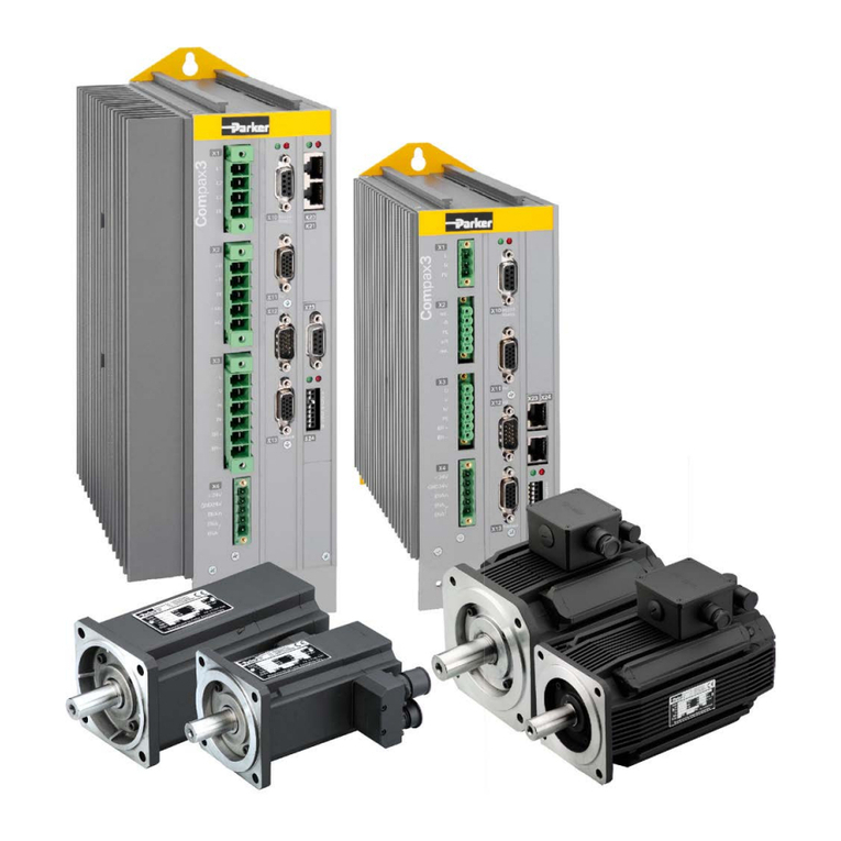
Parker
Parker Compax3S025V2 manual

Sanyo Denki
Sanyo Denki PY Series Installation and operation manual
