manuals.online logo
Brands
  1. Home
  2. •
  3. Brands
  4. •
  5. Festo
  6. •
  7. Servo Drive
  8. •
  9. Festo CMMT-AS-C7-11A-P3-EC-S1 User manual

Festo CMMT-AS-C7-11A-P3-EC-S1 User manual

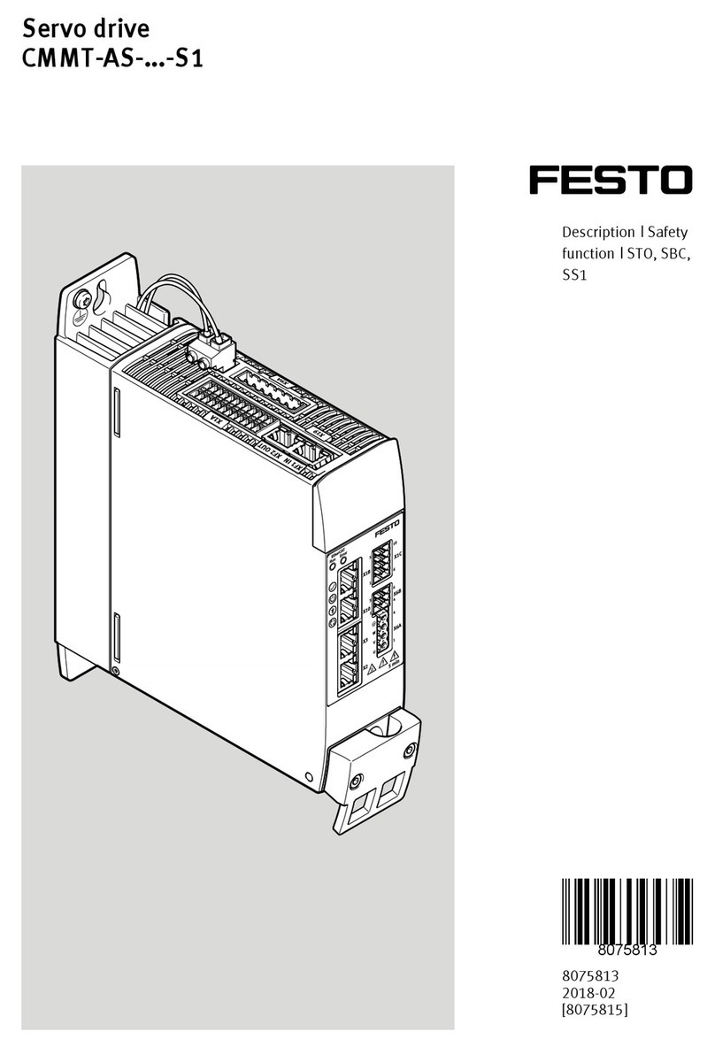
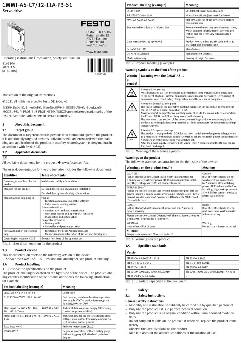
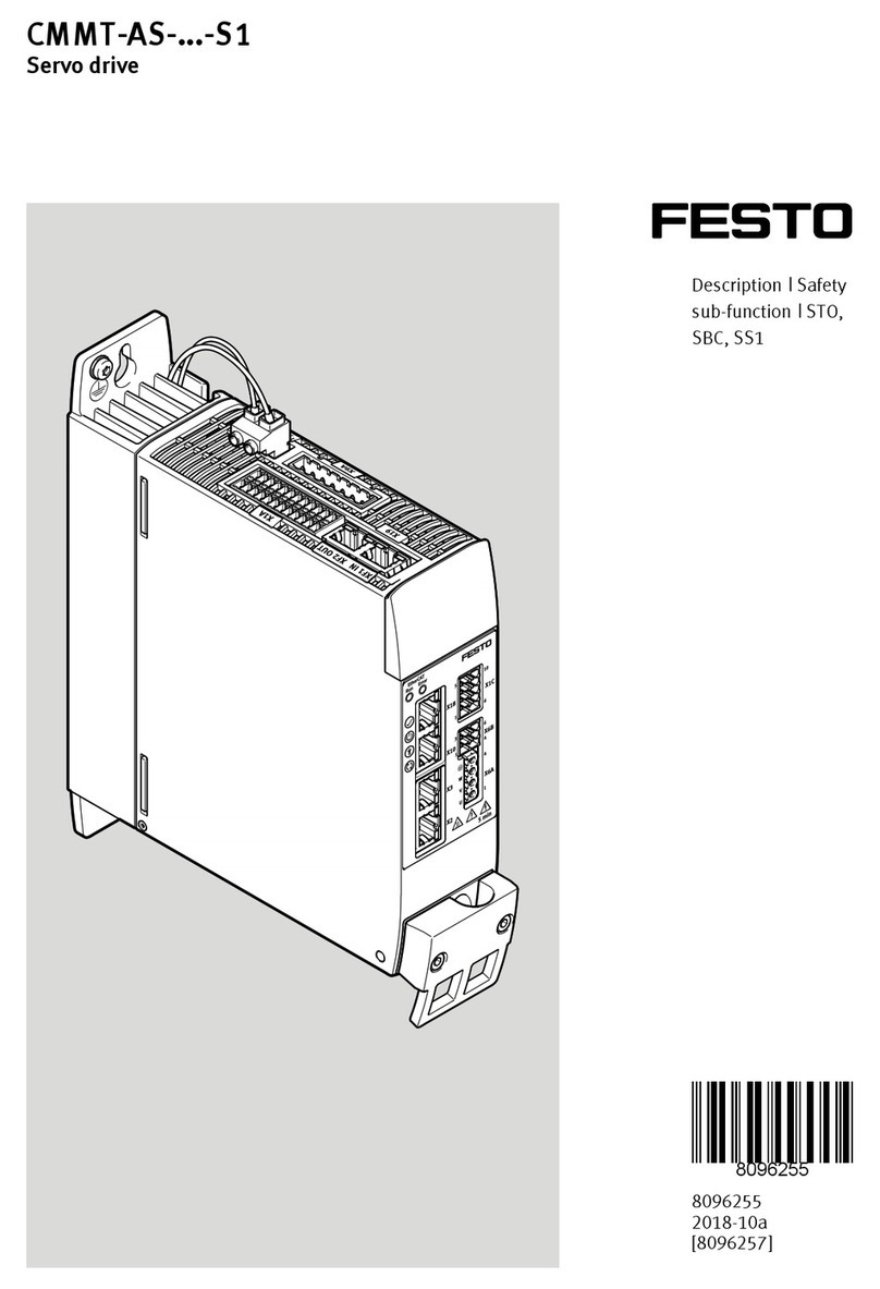
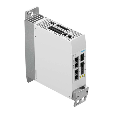
CMMT-AS-C7/12-11A-P3-S1
Servo drive
Festo SE & Co. KG
Ruiter Straße 82
73734 Esslingen
Deutschland
+49 711 347-0
www.festo.com
Operating instructions | Installation, Safety sub-function
8153813
2021-04b
[8153815]
Translation of the original instructions
© 2021 all rights reserved to Festo SE & Co. KG
EnDat®, EtherCAT®, EtherNet/IP®, DR. JOHANNES HEIDENHAIN®, Hiperface®,
PI PROFIBUS PROFINET®, TORX® are registered trademarks of the respective
trademark owners in certain countries.
1About this document
1.1 Target group
The document is targeted towards persons who mount and operate the product.
It is additionally targeted towards individuals who are entrusted with the plan-
ning and application of the product in a safety-related system (safety manual in
accordance with EN 61508).
1.2 Applicable documents
All available documents for the product è www.festo.com/sp.
The user documentation for the product also includes the following documents:
Identifier Table of contents
Operating instructions for the
product
Installation, safety sub-function
Manuals for the product Detailed description of assembly, installation
Detailed description of safety sub-function
Manual/online help plug-in Plug-in:
–Functions and operation of the software
–Initial commissioning wizard
Firmware functions:
–Configuration and parameterisation
–Operating modes and operational functions
–Diagnostics and optimisation
Bus protocol/control:
–Device profile
–Controller and parameterisation
Festo Automation Suite online
help
–Function of the Festo Automation Suite
–Management and integration of device-specific plug-ins
Operating instructions CDSB General functions of the operator unit
Tab. 1: User documentation for the product
1.3 Product version
This documentation refers to the following version of the device:
–Servo drive CMMT-AS-...-S1, revision R01 and higher, see product labelling
1.4 Product labelling
• Observe the specifications on the product.
The product labelling is located on the right side of the device. The product label-
ling enables identification of the product and shows the following information,
for example:
Product labelling (example) Meaning
CMMT-AS-C7-11A-P3-EC-S1 Order code
8101907 MM-YYYY : J302 Rev 00 Part number, serial number (MM = produc-
tion month, YYYY = production year, plant
number), revision (Rev)
Main input: 3 x 200 V AC - 10% … 480 V AC + 10%
48 … 62 Hz 7 ARMS
Technical data on power supply (alternating
current supply connection)
Motor out: 3 x 0 … Input V AC 0 … 599 Hz 7 ARMS
4 kW
Technical data for the motor output (output
voltage, max. output frequency, nominal cur-
rent, nominal output power)
TAMB: max. 40 °C Ambient temperature (TAMB)
IP10/20 PD2 Degree of protection, without mating plug/
with mating plug X9A attached; pollution
degree
Product labelling (example) Meaning
SCCR: 10 kA SCCR (short circuit current rating)
R-R-FTO-KC-2018-1054 KC mark certificate (test mark for Korea)
MAC: XX-XX-XX-XX-XX-XX first MAC address of the device for Ethernet
communication
See manual for additional information Reference to the existing user documentation,
which contains information on overload pro-
tection and the necessary external circuit
breaker.
Data matrix code 123456789AB Product key as a data matrix code and an 11-
character alphanumeric code
Festo SE & Co. KG Manufacturer
DE-73734 Esslingen Manufacturer’s address
Made in Germany Country of origin Germany
Tab. 2: Product labelling (example)
Warning symbols on the front of the product
Warnin
g
symbol
Meaning with the CMMT-AS-...
Attention! Hot surface
Metallic housing parts of the device can reach high temperatures during operation.
In the event of a fault, internal components may become overloaded. Overloading of
components can result in high temperatures and the release of hot gases.
Attention! General danger point
The touch current in the protective earthing conductor can exceed an alternating cur-
rent of 3.5 mA or a direct current of 10 mA.
Always connect both protective earthing connections to the mains-side PE connection,
the PE pin of [X9A] and PE earthing screw on the housing.
The minimum cross section of the protective earthing conductor must comply with
the local safety regulations for protective earthing conductors for equipment with high
leakage current.
5 min
Attention! Dangerous voltage
The product is equipped with DC link capacitors, which store dangerous voltage for up
to 5 minutes after the power supply is switched off. Do not touch power connections for
5 minutes after the power supply is switched off.
After the power supply is switched off, wait at least 5 minutes until the DC link capaci-
tors have discharged.
Tab. 3: Meaning of the warning symbols
Warnings on the product
The following warnings are attached to the right side of the device:
Warnings on the product (en, fr) Meaning
CAUTION
Risk of Electric Shock! Do not touch electrical connectors for
5 minutes after switching power off! Read manual before instal-
ling! High leakage current! First connect to earth!
Caution
Risk of electric shock! Do not
touch electrical connections
for 5 minutes after switching
power off! Read manual before
installing! High leakage current
after PE! First connect device to
protective earthing!
AVERTISSEMENT
Risque du choc électrique! Une tension dangereuse peut ètre pré-
sentée jusqu'à 5 minutes aprés avoir coupé l'alimentation ! Lire le
manuel avant installation ! Courant de défaut élevée ! Relier tout
d´abord à la terre !
DANGER
Risk of Electric Shock! Disconnect power and wait 5 minutes
before servicing.
Danger
Risk of electric shock! Discon-
nect power and wait 5 minutes
before servicing.
Risque du choc électrique! Débranchez l'alimentation et attendez
5 min. avant de procéder à l'entretien.
WARNING
Hot surface - Risk of burn!
Warning
Hot surface – danger of burns!
ATTENTION
Risque de temperature élevée en surface!
Tab. 4: Warnings on the product
1.5 Specified standards
Version
IEC 61800-5-1:2016 EN 61800-2:2015
EN ISO 13849-1:2015 EN 61800-3:2004+A1:2012
EN 60204-1:2006+A1:2009+AC2010 EN 61800-5-2:2017
EN 60529:1991+A1:2000+A2/AC:2019 EN 62061:2005+AC:2010+A1:2013+A2:2015
EN 61508 Parts 1-7:2010 –
Tab. 5: Standards specified in the document
2 Safety
2.1 Safety instructions
General safety instructions
–Assembly and installation should only be carried out by qualified personnel.
–Only use the product if it is in perfect technical condition.
–Only use the product in original status without unauthorised modifications.
–Do not carry out repairs on the product. If defective, replace the product imme-
diately.
–Observe labelling on the product.
–Take into consideration the ambient conditions at the location of use.
The safety function might fail and malfunctions might occur if you do not
comply with the parameters required for the ambient and connection condi-
tions.
–This product can generate high frequency malfunctions, which may make it nec-
essary to implement interference suppression measures in residential areas.
–Wear required personal protective equipment during transport and during
assembly and disassembly of very heavy product versions.
–Never remove or insert a plug connector while live.
–Do not loosen any screws on the product other than the following:
–Earthing screw on the cooling element for mounting the PE connection on the
mains side
–Retaining screws of the shield clamp on the housing front
–Only when used in IT networks: screw for connecting the internal mains filter
to PE
–Install the product in a suitable control cabinet. The minimum degree of protec-
tion required for the control cabinet is IP54.
–Once installed, only operate the product if all the necessary protective meas-
ures have been implemented (è EN 60204-1).
–Fully insulate all conducting lines on the product. We recommend wire end
sleeves with plastic sleeves for wiring power connections. During wiring, please
observe the necessary strip lengths.
–Information on strip length è Manual Assembly, Installation.
–Ensure correct protective earthing and shield connection.
–Prior to commissioning, ensure that the resulting movements of the connected
actuator technology cannot endanger anyone.
–During commissioning: systematically check all control functions and the com-
munication and signal interface between controller and servo drive.
–The product is equipped with DC link capacitors, which store dangerous voltage
for up to 5 minutes after the power supply is switched off. Before working
on the product, switch off the power supply via the main switch and secure
it against being switched on again unintentionally. Before touching the power
connections, wait at least 5 minutes.
–Take into consideration the legal regulations for the installation location.
–Keep the documentation somewhere safe throughout the entire product life-
cycle.
In the event of damage caused by unauthorised manipulation or any use other
than the intended use, the guarantee will be invalidated and the manufacturer will
not be liable for damages.
In the event of damage caused by using unauthorised software or firmware with
the device, the warranty will be invalidated, and the manufacturer will not be
liable for damages.
Safety instructions for the safety sub-functions
It is only possible to determine whether the product is suitable for specific appli-
cations by also assessing further components of the subsystem.
Analyse and validate the safety function of the entire system.
Check the safety functions at adequate intervals for proper functioning. It is the
responsibility of the operator to choose the type and frequency of the checks
within the specified time period. The manner in which the test is conducted
must make it possible to verify that the safety device is functioning perfectly in
interaction with all components. Time period for cyclical test è 13.1 Technical
data, safety engineering.
Prior to initial commissioning, wire the control inputs of the safety sub-functions
STO and SBC. The safety sub-functions STO and SBC are available on the CMMT-
AS on delivery without the need for any additional parameterisation.
2.2 Intended use
The servo drive CMMT-AS is intended for supply and control of AC servo motors.
The integrated electronics permit regulation of torque (current), rotational speed
and position.
Use exclusively:
–in perfect technical condition
–in original condition without unauthorised modifications; only the extensions
described in the documentation supplied with the product are permitted
–within the limits of the product defined by the technical data è Technical data
–in an industrial environment
The safety function might fail and malfunctions might occur if you do not comply
with the parameters required for the ambient and connection conditions.
The CMMT-AS-...-S1 supports the following safety sub-functions in accordance
with EN 61800-5-2:
–Safe torque off (STO/Safe torque off)
–Safe brake control (SBC/Safe brake control)
–Safe stop 1 (SS1/Safe stop 1), achievable with suitable safety relay unit and
appropriate circuitry of the servo drive
The safety sub-function STO is intended to switch off the torque of the connected
motor, thereby preventing an unexpected restart of the motor.
The safety sub-function SBC is intended to safely hold the motor and axis in
position at standstill.
The safety sub-function SS1 is intended for performing a rapid stop with subse-
quent torque switch-off.
2.2.1 Application areas
The device is intended for use in an industrial environment and with appropriate
measures in commercial, residential and mixed areas.
The device is intended for installation in a control cabinet. The minimum degree of
protection required for the control cabinet is IP54.
The device can be operated in TN, TT and IT systems if certain requirements are
met.
Information on allowed and prohibited mains types of system earthing and neces-
sary measures for use in IT networks è Manual Assembly, Installation.
Safety sub-functions may only be used for applications for which the stated safety
reference values are sufficient è 13.1 Technical data, safety engineering.
2.2.2 Permissible components
The logic power supply must meet the requirements of EN 60204-1 (protective
extra-low voltage, PELV).
If holding brakes and clamping units without certification are used, a risk assess-
ment is required to assess their suitability for the related safety-oriented applica-
tion.
In addition to the requirements of EN 60204-1, the following requirements apply
to other components of the drive system from EN 61800-5-2:
–Annex D.3.5 and D.3.6 for motors
–Annex D.3.1 for motor and brake cables
–Annex D.3.4 for mating plugs
Components approved by Festo for the CMMT-AS fulfil these requirements.
2.3 Foreseeable misuse
Foreseeable misuse, general
–Use outside the limits of the product defined in the technical data.
–Cross-wiring of the I/O signals of more than 10 servo drives CMMT-AS.
–Use in IT networks without insulation monitors for detection of earth faults.
If the device is operated in IT networks, the potential conditions will change in
the event of a fault (earth fault on the feeding mains supply). As a result, the
rated voltage of 300 V to PE – which has important implications for the design
of insulation and network disconnection – will be exceeded. This error must be
detected.
–Use of a diagnostic output for connection of a safety function.
The diagnostic outputs STA and SBA are not part of the safety circuit. The
diagnostic outputs are used to improve diagnostic coverage of the related
safety sub-function. The diagnostic outputs may only be used in combination
with the related safe control signals (AND operation) plus a reliable time moni-
toring function in the safety relay unit for the purpose of switching additional
safety-critical functions.
Foreseeable misuse of the safety sub-function STO
–Use of the STO function without external measures for drive axis influenced by
external torques.
If external torques influence the drive axis, use of the safety sub-function STO
on its own is not suitable for stopping the axis safely. Additional measures are
required to prevent dangerous movements of the drive axis, such as use of a
mechanical brake in combination with the safety sub-function SBC.
–Disconnection of the motor from the power supply.
The safety sub-function STO does not disconnect the drive from the power
supply as defined by electrical safety.
Foreseeable misuse of the safety sub-function SBC
–Use of an unsuitable holding brake or clamping unit, also in view of:
–Holding or brake torque and emergency brake characteristics, if required.
–Frequency of actuation
–Use of an unsuitable logic voltage supply
2.4 Training of qualified personnel
The product may be installed and placed in operation only by a qualified electro
technician, who is familiar with the topics:
–installation and operation of electrical control systems
–applicable regulations for operating safety-engineering systems
Work on safety-related systems may only be carried out by qualified personnel
trained in safety engineering.
2.5 CE marking
The product has the CE marking.
The product-related EC/EU directives and standards are listed in the declaration
of conformity è www.festo.com/sp.
2.6 Safety engineering approval
The product is a safety device in accordance with the Machinery Directive. For
details of the safety-oriented standards and test values that the product complies
with and fulfils, see è 13.1 Technical data, safety engineering.
2.7 UL/CSA certification
Technical data and environmental conditions may be subject to change in order to
comply with Underwriters Laboratories Inc. (UL) certification requirements for the
USA and Canada.
Deviating values è 13.4 Technical data UL/CSA certification.
3 Additional information
–Contact the regional Festo contact if you have technical problems
è www.festo.com.
–Accessories and spare parts è www.festo.com/catalogue.
Firmware, software or configuration files è www.festo.com/sp.
4Product overview
4.1 Scope of delivery
Component Number
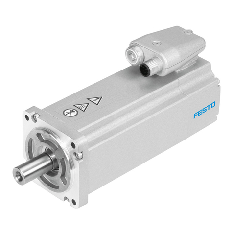
Servo drive CMMT-AS-... 1
Operating instructions CMMT-AS-... 1
Tab. 6: Scope of delivery
4.2 System structure
The servo drive CMMT-AS is a 1-axis servo drive. Depending on the product
variant, the following components, which are necessary for standard applications,
are integrated into the device or into the cooling profile of the device:
–Mains filter (guarantees immunity to interference and limits conducted emis-
sions)
–Electronics for DC link voltage conditioning
–Power stage (for motor control)
–Braking resistor (integrated into the cooling element)
–Brake chopper (switches the braking resistor in the DC link circuit, if and when
required)
–Temperature sensors (for monitoring the temperature of the power module and
of the air in the device)
–Fan in the cooling profile
The servo drive features a real-time Ethernet interface for process control. Var-
ious bus protocols are supported depending on the product design (EtherCAT,
EtherNet/IP or PROFINET).
The device can be parameterised via a PC using either the real-time Ethernet
interface or the separate standard Ethernet interface.
Festo recommends use of servo motors, electromechanical drives, lines and
accessories from the Festo accessory programme.
1
2
3
4
5
6
7
8
Fig. 1: System structure (example)
1
Bus/network
2
Main switch
3
Automatic circuit breaker/fuses
and all-current-sensitive RCD
(residual current device)
(optional)
4
Fixed power supply for logic
voltage supply 24 V DC (PELV)
5
External braking resistor
(optional)
6
Servo drive CMMT-AS
7
Servo motor (here EMME-AS)
8
PC with Ethernet connection for
parameterisation
4.2.1 Overview of connection technology
12
3
4
5
6
7
8
9
10
11
12
13
14
15
16
Fig. 2: Connections of the CMMT-AS-C7/C12-11A-P3 (example)
1
PE connection, housing
2
[X9A] Mains and DC link circuit
connection
3
[X9C] Logic voltage
4
[XF2 OUT] RTE interface port 2
5
[XF1 IN] RTE interface port 1
6
[X1C] inputs/outputs for the axis
7
[X6B] motor auxiliary connection
8
[X6A] motor phase connection
9
Shield clamp of motor cable
10
[X2] encoder connection 1
11
[X3] encoder connection 2
12
[X10] device synchronisation
13
[X18] standard Ethernet
14
[X5] connection for operator unit
(behind the blind plate)
15
[X1A] I/O interface
16
[X9B] connection for braking
resistor
4.3 Safety sub-functions
4.3.1 Function and application
The servo drive CMMT-AS-...-S1 has the following safety-related performance fea-
tures:
–Safe torque off (STO)
–Safe brake control (SBC)
–Safe stop 1 (SS1) with use of a suitable external safety relay unit and appro-
priate wiring of the servo drive
–Diagnostic outputs STA and SBA for feedback of the active safety sub-function
4.3.2 Safety sub-function STO
Function and application of STO
The safety sub-function STO switches off the driver supply for the power semi-
conductor, thus preventing the power output stage from supplying the energy
required by the motor. The power supply to the drive is safely disconnected
when the safety sub-function STO is active. The drive cannot generate torque and
so cannot perform any dangerous movements. With suspended loads or other
external forces, additional measures must be put in place to prevent movements
being performed (e.g. mechanical clamping units). In the STO state, the standstill
position is not monitored.
The machines must be stopped and locked in a safe manner. This especially
applies to vertical axes without automatic locking mechanisms, clamping units or
counterbalancing.
NOTICE
If there are multiple errors in the servo drive, there is a danger that the drive will
move. Failure of the servo drive output stage during the STO status (simultaneous
short circuit of 2 power semiconductors in different phases) may result in a
limited detent movement of the rotor. The rotation angle/travel corresponds to a
pole pitch. Examples:
• Rotating motor, synchronous machine, 8-pin è Movement < 45° at the motor
shaft
• Linear motor, pole pitch 20 mm è Movement < 20 mm at the moving part
STO request
The safety sub-function STO is requested on 2 channels by simultaneously
switching off the control voltage at both control inputs #STO-A and #STO-B.
STO feedback via STA diagnostic contact
The status of the safety sub-function STO can be reported to the safety relay unit
via the STA diagnostic output.
The STA diagnostic output indicates whether the safe status has been reached for
the safety sub-function STO. The STA diagnostic output switches to high level only
when STO is active on 2 channels via the control inputs #STO-A and #STO-B.
#STO-A #STO-B STA
Low level Low level High level
Low level High level Low level
High level Low level Low level
High level High level Low level
Tab. 7: Level of STA
If protective functions are triggered on both channels (STO-A and STO-B), e.g. if
the voltage at STO-A and STO-B is too high, the internal protective functions
switch off and STA also delivers a high level signal.
Recommendation: the safety relay unit should check the status of the diagnostic
output whenever there is a STO request. The level of STA must change according
to the logic table. The safety relay unit can cyclically test the signals #STO-A and
#STO-B for high level with low test pulses and for low level with high test pulses.
4.3.3 Safety sub-function SBC
Function and application of SBC
The safety sub-function SBC provides safe output signals for the control of brakes
(holding brakes or clamping units). The brakes are controlled on 2 channels by
switching off the voltage at the following outputs:
–Safe output BR+/BR– [X6B] for the holding brake of the motor
–Safe output BR-EXT/GND [X1C] for the external brake/clamping unit
The holding brake and/or clamping unit engage and slow the motor or axis. The
purpose of this is to slow down dangerous movements by mechanical means. The
braking time is dependent on how quickly the brake engages and how high the
energy level is in the system.
The use of just one brake is only possible when performance requirements are
low è Tab. 52 Safety reference data for the safety sub-function SBC. To do this,
connect the brake either to BR+/BR– or to BR-EXT.
NOTICE
If there are suspended loads, they usually drop if SBC is requested simultane-
ously with STO. This can be traced back to the mechanical inertia of the holding
brake or clamping unit and is thus unavoidable. Check whether safety sub-func-
tion SS1 is better suited to your application.
SBC may only be used for holding brakes or clamping units which engage in the
de-energised state. Ensure the lines are protected when installed.
SBC request
The safety sub-function SBC is requested on 2 channels by simultaneously
switching off the control voltage at both control inputs #SBC-A and #SBC-B:
–The #SBC-A request switches off the power to the signals BR+/BR-.
–The #SBC-B request switches off the power to the signal BR-EXT.
In the event of a power failure in the logic voltage supply of the servo drive, power
is also cut off to the brake outputs.
SBC feedback via SBA diagnostic contact
The 2-channel switching of the brake is indicated via the SBA output. SBA is
used to report the status of the safety sub-function SBC for diagnostic purposes,
e.g. by reporting it to an external safety relay unit.
The SBA diagnostic output indicates whether the safe status has been reached for
the safety sub-function SBC. It is set if the following two conditions are fulfilled:
–Switching off of both brake outputs is requested (#SBC-A = #SBC-B = low level)
–The internal diagnostic functions have determined that there is no internal error
and both brake outputs are de-energised (switched off).
Testing the safety sub-function SBC
Test inputs #SBC-A and #SBC-B separately from each other and together. The
diagnostic feedback may only be set to high level when inputs #SBC-A and
#SBC-B are both requested. If the signal behaviour does not correspond to
expectations, the system must be set to a safe condition within the reaction time.
It is essential that time monitoring be provided in the safety relay unit.
The safety sub-function SBC with feedback via SBA must be tested at least 1x
within the space of 24 h.
•Test SBA feedback based on the SBC-A and SBC-B level according to the
following table.
#SBC-A (BR+) #SBC-B (BR-Ext) SBA
Low level Low level High level
Low level High level Low level
High level Low level Low level
High level High level Low level
Tab. 8: Testing all SBC levels
While you are testing the safety sub-function SBC, discrepancy error detection
may be activated in the CMMT-AS if the test lasts longer than 200 ms. If a corre-
sponding error message is output by the basic unit, you will need to acknowledge
it.
Evaluation of SBA
Recommendation: evaluation with every actuation.
• Check SBA feedback whenever there is a request.
Requirements for the brake
Requirements for the brakeè Manual Safety sub-function
Brake test
• Check whether a brake test is required. The DGUV information sheet “Gravity-
loaded axis” provides information on this.
4.3.4 Safety sub-function SS1
Together with a suitable safety relay unit, the following can be achieved:
–Safe stop 1 time controlled (SS1-t/Safe stop 1 time controlled;) triggering of
motor deceleration and, after an application-specific time delay, triggering of
the safety sub-function STO
Safety sub-function SS1 è Manual Safety sub-function
4.3.5 Fault exclusion
Put suitable measures in place to prevent faulty wiring:
–Exclude wiring faults in accordance with EN 61800-5-2
–Configure the safety relay unit to monitor the outputs of the safety relay unit
and wiring up to the servo drive
4.3.6 Safety relay unit
Use suitable safety relay units with the following characteristics:
–2-channel outputs with
–Detection of shorts across contacts
–Required output current (also for STO)
–Low test pulses up to a maximum length of 1 ms
–Evaluation of the diagnostic outputs of the servo drive
Safety relay units with high test impulses can be used with the following restric-
tions:
–Test impulses up to 1 ms in length
–Test impulses are not simultaneous/overlapping on #STO-A/B and #SBC-A/B
–The resulting safety-related classification depends on the evaluation of diag-
nostic feedbacks STA, SBA è 13.1 Technical data, safety engineering, safety
reference data STO and SBC.
5 Transport and storage
–Protect the product during transport and storage from excessive stress factors.
Excessive stress factors include:
–mechanical stresses
–impermissible temperatures
–moisture
–aggressive atmospheres
–Store and transport the product in its original packaging. The original pack-
aging offers sufficient protection from typical stresses.
6 Assembly
Dimensions CMMT-AS-C7 / C12-11A-P3...
Fig. 3: Dimensions
Dimen-
sion
L1 L2 L3 L4 L5 L6 L7
[mm] Approx.
319
276 300 22 10 6 13
Tab. 9: Dimensions CMMT-AS-C7 / C12-11A-P3... Part 1
Dimen
sion
H1 H2 B1 B2 B3 D1 D2 D3
[mm] Approx.
224
Approx.
205
Approx.
75
44 B1/2 R5.5 5.5 5.5
Tab. 10: Dimensions CMMT-AS-C7 / C12-11A-P3... Part 2
6.1 Mounting distances
The servo drives of the series CMMT-AS can be arrayed next to each other. When
arraying devices, the required minimum distance must be maintained so that the
heat generated during operation can be dissipated by allowing sufficient air flow.
Mounting distances for CMMT-AS-C7/C12-11A-P3...
Fig. 4: Mounting distances and installation clearance for CMMT-AS-C7/
C12-...-11A-P3 (3-phase)
Servo drive H1 H21) L1 L2 L3
CMMT-AS-C7-11A-P3... [mm] 100 70 78 70 300
CMMT-AS-C12-11A-P3... [mm]
1) An installation clearance of 150 mm is recommended for compliance with clearance H2 and for optimum
routing of the motor and encoder cables on the underside of the housing!
Tab. 11: Mounting distances and installation clearance for CMMT-AS-C7/C12-11A-
P3...
This means that a minimum lateral distance of approx. 3 mm (78 mm - 75 mm)
must be observed in relation to neighbouring CMMT-AS devices.
For adjacent third-party devices, Festo recommends a distance of at least 10 mm
(surface temperature of third-party device max. 40°C). The double mating plug
for cross-wiring of the connection [X9A] protrudes by approx. 6 … 7 mm over the
right side of the device. However, this does not create an obstacle for arraying
additional CMMT-AS.
6.2 Installation
Assembly instructions
–Use a control cabinet with degree of protection IP54 or higher.
–Always install device vertically in the control cabinet on a closed surface (mains
supply lines [X9A] point upwards).
–Screw device flat to a sufficiently stable mounting surface so that good
heat transfer from the cooling element to the mounting surface is ensured
(e.g. screw to the rear wall of the control cabinet).
–Maintain minimum distances and installation clearance to guarantee sufficient
air flow. The ambient air in the control cabinet must be able to flow through the
device from bottom to top without hindrance.
–Take into account the required clearance for the wiring (connecting cables of
the device must be routed from above and from the front).
–Do not mount any temperature-sensitive components near the device. The
device can become very hot during operation (switch-off temperature of the
temperature monitoring function è Technical data).
–When assembling several devices in a device compound, consider general rules
for cross-wiring. For DC link coupling, higher-power devices must be placed
closer to the mains supply.
–If there is a voltage supply to the device when the control cabinet is open,
vertical access to the bottom and top of the device must be prevented.
For mounting on the rear wall of the control cabinet, the servo drive cooling
element has a slot on the top in the shape of a keyhole and an ordinary slot on the
bottom.
Assembly of the servo drive
WARNING
Danger of burns through hot escaping gases and hot surfaces.
In case of error, incorrect wiring or incorrect polarity of the connections [X9A],
[X9B] and [X6A], internal components can be overloaded. High temperatures can
develop and hot gases can be released.
• Have an authorised electrician perform the installation according to the docu-
mentation.
WARNING
Danger of burns from hot housing surfaces.
Metallic housing parts can accept high temperatures in operation. In particular,
the braking resistor installed in the profile on the back side can become very hot.
Contact with metal housing parts can cause burn injuries.
• Do not touch metallic housing parts.
• After the power supply is switched off, let the device cool off to room tempera-
ture.
•Mount the servo drive on the rear wall of the control cabinet with suitable
screws while complying with the assembly instructions.
7Installation
7.1 Safety
WARNING
Risk of injury from electric shock.
Contact with live parts at the power connections [X6A], [X9A] and [X9B] can result
in severe injuries or death.
•Do not pull out power supply plugs while live.
• Before touching, wait at least 5 minutes after switching off the load voltage to
allow the intermediate circuit to discharge.
WARNING
Risk of injury from electric shock.
The leakage current of the device to earth (PE) is > 3.5 mA AC or 10 mA DC.
Touching the device housing if there is a fault can result in serious injuries or
death.
Before commissioning, also for brief measuring and test purposes:
• Connect PE connection on the mains side at the following positions:
• Protective earth connection (earthing screw) of the housing
• PE pin of the connection [X9A] (power supply)
The cross section of the PE conductors must be at least equal to the
cross section of the mains conductor L at [X9A].
• Connect motor cable to connection [X6A] and the shield of the motor cable on
the front side to PE via the shield clamp of the servo drive.
• Observe the regulations of EN 60204-1 for the protective earthing.
WARNING
Danger of burns through hot escaping gases and hot surfaces.
In case of error, incorrect wiring or incorrect polarity of the connections [X9A],
[X9B] and [X6A], internal components can be overloaded. High temperatures can
develop and hot gases can be released.
• Have an authorised electrician perform the installation according to the docu-
mentation.
WARNING
Risk of injury from electric shock in the event of incomplete insulation at the
power connections [X6A], [X9A] and [X9B].
Before operating, plugging in or unplugging the operator unit CDSB or a con-
nector from a hot-plug-capable interface, the following points must be fulfilled:
• The conducting lines at the device are completely insulated.
• The protective earthing (PE) and the shield connection are correctly connected
to the device.
• The housing is free of damage.
WARNING
Risk of injury due to overheating and electric shock with faulty live components
Closing the branch-circuit protective device with faulty live components may
cause fire or electric shock.
•The opening of the branch-circuit protective device may be an indication that
a fault current has been interrupted. To reduce the risk of fire or electric
shock, current-carrying parts and other components of the controller should
be examined and replaced if damaged. If burnout of the current element of
an overload relay occurs, the complete overload relay must be replaced.
Information for operation with safety functions
NOTICE
Check the safety functions to conclude the installation process and after every
modification to the installation.
During installation of safety-related inputs and outputs, also observe the fol-
lowing:
–Comply with all specified requirements, e.g.:
–Surrounding area (EMC)
–Logic and load voltage supply
–Mating plug
–Connecting cables
–Cross-wiring
–Additional information è Manual Assembly, Installation.
–The maximum permissible cable length between the safety relay unit and the
plug of the I/O interface is 3 m.
–Comply with the requirements of EN 60204-1 for the installation. In the event of
a fault, the voltage must not exceed 60 V DC. The safety relay unit must switch
off its outputs in the event of a fault.
–Install wiring between the safety relay unit and the I/O interface of the servo
drive in such a way as to eliminate the risk of a short circuit between the
conductors or to 24 V, as well as a cross circuit è EN 61800-5-2, Annex
D.3.1. Otherwise, the safety relay unit must feature detection of shorts across
contacts and, in the event of a fault, must switch off the control signals on 2
channels.
–Use only suitable mating plugs and connecting cables è Manual Assembly,
Installation.
–Prevent conductive contamination between neighbouring plug pins.
–Make sure that no bridges or similar can be inserted parallel to the safety
wiring. For example, use the maximum wire cross section or appropriate plastic
wire end sleeves.
–Use twin wire end sleeves for cross-wiring safety-related inputs and outputs.
A maximum of 10 devices may be cross-wired when cross-wiring inputs and
outputs è Manual Assembly, Installation.
–The safety relay unit and its inputs and outputs must meet the necessary safety
classification of the safety function that is required for the specific case.
–Connect each of the control inputs to the safety relay unit on 2 channels using
parallel wiring.
–Only use permitted motor cables for the BR+/BR– connection.
–If the diagnostic output of the safety sub-function concerned has to be evalu-
ated: connect diagnostic output directly to the safety relay unit. Evaluation
of the diagnostic output is either mandatory or optional depending on which
safety classification is desired.
–If diagnostic outputs are cross-wired for a device compound: wire diagnostic
outputs as a ring. Run the two ends of the ring to the safety relay unit and
monitor for discrepancies.
7.2 Residual current protective device
WARNING
Risk of injury from electric shock.
This product can cause a DC current in the residual-current conductor in case of
error. In cases where a residual current device (RCD) or a residual current monitor
(RCM) is used to protect against direct or indirect contact, only the type B kind of
RCD or RCM is permitted on the power supply side of this product.
Information on the residual current protective device è Manual Assembly, Instal-
lation.
The touch current in the protective earthing conductor can exceed an alternating
current of 3.5 mA or a DC current of 10 mA. Always connect both protective
earthing connections to the mains-side PE connection, the PE pin of [X9A] and
PE earthing screw on the housing. The minimum cross section of the protective
earthing conductor must comply with the local safety regulations for protective
earthing conductors for equipment with high leakage current.
7.3 Mains fuse
The CMMT-AS does not have an integrated fuse at the mains input or in the DC
link circuit. An external fuse is required at the mains supply of the device. A device
group coupled in the DC link circuit must be protected by a common mains fuse.
• Use only circuit breakers and fuses that have the relevant approval and meet
the specifications and protection requirements stated below.
Requirements for circuit breakers (automatic circuit breakers)
Type of protection Circuit breaker
max. permissible rated cur-
rent
[A] 40
Restrictions concerning line protection è Tab. 13 Line
protection requirements
Short circuit current rating
SCCR of mains fuse
[kA] min. 10
Approvals IEC 60947-2
Rated voltage [V AC] min. 400
Overvoltage category III
Pollution degree 2
Characteristic C
Tab. 12: Requirements for circuit breakers and fuses
The circuit breaker is used for line protection. The rated current of the circuit
breaker must be less than or equal to the approved current rating of the selected
conductor cross section. The circuit breaker must also take into account the
overload case and must not trip (overload case: a 3-fold increase in the input
current for 2 s).
Line protection requirements
Description Cable cross
section at
[X9A] in
[mm²]
Mains fuse [A]1)
CMMT-AS- C7-11A-P3 C12-11A-P3
Minimum fuse protec-
tion
1.52) 10 16
Maximum fuse protection of an individual device or a device group
without heat-resistant
cable
4 25
6 32
with heat-resistant
cable3)
4 32
6 40
1) Specifications according to DIN VDE 0298-4:2013, permissible currents according to EN 60204-1 may
differ (depending on installation type and temperature)
2) depending on the type of installation of the cables, wiring with min. 2.5 mm² may be required for the
CMMT-AS-C12-11A-P3.
3) no derating up to an ambient temperature of 50 °C and a cable temperature higher than 70 °C (max. cable
temperature 90 °C)
Tab. 13: Line protection requirements
Fuse protection when load circuit is supplied with DC power
The CMMT-AS allows the load circuit to be supplied with DC power. With DC
power, external fuse protection is once again required in the form of short circuit
protection and line protection. The fuse that is used must be capable of reliably
disconnecting the maximum DC supply voltage that could occur and the potential
short circuit current (SCCRDC).
Maximum fuse protection: 40 A
If fuse protection is to be avoided on the DC side, check whether the fuse protec-
tion could alternatively be installed on the AC side upstream of the DC fixed power
supply.
7.4 Permissible and impermissible mains types of system earthing
Information on allowed and prohibited mains types of system earthing and neces-
sary measures for use in IT networks è Manual Assembly, Installation.
Leakage currents in IT systems
High-frequency leakage currents to protective earthing (PE) may be encountered
even in IT systems (IT = Isolé Terre) during operation of the servo drive. The
leakage currents flow to the PE through the coupling capacitances of the motor
cable and the motor and back to the servo drive through the coupling capacitance
of the isolating transformer via the load supply. The coupling capacitances can be
minimised by selection of a suitable isolating transformer and keeping the motor
cable as short as possible.
WARNING
Risk of injury from electric shock.
The servo drive generates high-frequency leakage currents, which can lead to
dangerous contact currents on the external conductors and the neutral conductor
of the IT system. Touching the mains conductor or the neutral conductor can result
in serious injuries or death.
• Before working on the IT systems, disconnect the servo drive from the mains.
7.5 Connection of the mains side PE conductor
All PE conductors must always be connected prior to commissioning for safety
reasons. Observe the regulations of EN 60204-1 when implementing protective
earthing.
Always connect PE connection on the mains side (PE rail in the control cabinet) at
the following positions:
–PE pin of the connection [X9A]
–PE connection (earthing screw) next to the upper slot of the cooling element
The cross section of the PE conductors must be at least equal to the cross section
of the mains conductors L at [X9A]. Wire individually wired devices in a star shape.
Observe the requirements for cross-wiring for cross-wired devices. Recommenda-
tion: use copper earthing strap (advantageous for EMC).
1. Equip PE conductors for the earthing screw with a suitable cable lug.
2. Tighten earthing screw with a TORX screwdriver of size T20 (tightening torque
1.8 Nm ± 15 %).
1
Fig. 5: PE connection (earthing screw)
1
PE connection (earthing screw)
7.6 Information on EMC-compliant installation
A mains filter is integrated into the device. The mains filter fulfils the following
tasks:
–Guarantees the device’s immunity to interference
–Limits the conducted emissions of the device
The device fulfills the requirements of the relevant product standard EN 61800-3
with suitable installation and wiring of all connecting cables.
The category that the device fulfils is dependent on the filter measures used and
the motor cable length. The integrated mains filter is designed so the device fulfils
the following categories when operated as an individual device:
CMMT-AS... PWM
[kHz]
required measures Max. permissible motor
cable length [m]
Category C2: operation in the first environment (residential area)
-C7-11A-P3
-C12-11A-P3
8 – (none) 10
Category C3: operation in the second environment (industrial area)
-C7-11A-P3
-C12-11A-P3
8 – (none) 25
external mains filter 100
Tab. 14: Category according to the pulse-width modulation frequency and the
cable length
–If set-up and commissioning are performed by a professional with the neces-
sary experience for setting up and commissioning drive systems, including
their EMC aspects, category C2 devices can be used in the first environment
(residential area).
–For operation of category C2 devices, limit values for the harmonic currents
in the network (EN 61000-3-2 or EN 61000-3-12) apply, depending on the
connected load of the machine. Please check whether this is the case for your
facility/system.
–Category C3 devices are intended for use in the second environment only
(industrial environment). Use in the first environment is not permitted.
This product can generate high frequency interference, which may make it neces-
sary to implement interference suppression measures in residential areas.
In practice, the combination of the components used and their properties influ-
ence the achievable length of the motor cable è Manual Assembly, Installation.
7.7 Connection examples
Connection plan, 3-phase mains connection
1
4
2
3
5
6
7
Fig. 6: Connection example
1
Braking resistor
2
Circuit breaker or 3 x fuses
3
Main switch/main contactor
4
Line choke if required (for cate-
gory C2)
5
PELV fixed power supply for 24 V
supply
6
Encoder 2 (optional)
7
Encoder 1
STO connection example
The safety sub-function STO (safe torque off) is triggered by an input device that
makes the safety request (e.g. light curtain).
1 2 3
4
Fig. 7: STO sample circuit
1Input device for safety request
(e.g. light curtain)
2Safety relay unit
3Servo drive CMMT-AS
4Drive axle
Information on the sample circuit
The safety request is passed on to the servo drive on 2 channels via the inputs
#STO-A and #STO-B at the connection [X1A]. This safety request results in the
2-channel switch-off of the driver supply to the servo drive’s power output stage.
The safety relay unit can use the STA diagnostic output to monitor whether the
safe status has been reached for the safety sub-function STO.
SBC connection example
The safety sub-function SBC (safe brake control) is triggered by an input device
that makes the safety request.
1 2 3
4
Fig. 8: SBC sample circuit
1Input device for safety request
(e.g. light curtain)
2Safety relay unit
3Servo drive CMMT-AS
4Control (here solenoid valve
example) of the clamping unit
Information on the sample circuit
The safety request is passed on to the servo drive on 2 channels via the inputs
#SBC-A and #SBC-B at the connection [X1A].
–The request via the input #SBC-A switches off power to the signals BR+ and BR-
at the connection [X6B]. This de-energises and closes the holding brake.
–The request via the input #SBC-B switches off power to the signal BR-EXT at the
connection [X1C]. This shuts off power to the control of the external clamping
unit. The clamping unit closes.
–The safety relay unit monitors the SBA diagnostic output and checks whether
the safe status has been reached for the safety sub-function SBC.
7.8 Interfaces
Observe the requirements for mating plugs è Manual Assembly, Installation.
7.8.1 [X1A], inputs and outputs for the higher-order PLC
The I/O interface [X1A] is located on the top of the device. This interface offers
access to functional and safety-related inputs and outputs of the device. These
include, for example:
–Digital inputs for 24 V level (PNP logic)
–Digital outputs for 24 V level (PNP logic)
–Signal contact for safety chain (RDY-C1, RDY-C2)
–Differential analogue input ±10 V control voltage
The inputs and outputs of this I/O interface are used for coupling to a higher-
order PLC. The safety-related inputs and outputs are connected to a safety relay
unit.
[X1A] Pin Function Description
24 RDY-C1 Normally open contact:
ready for operation mes-
sage (Ready)
23 RDY-C2
22 STA Diagnostic output Safe
torque off acknowledge
21 SBA Diagnostic output Safe
brake control acknowl-
edge
20 – reserved, do not connect
19 –
18 SIN4 Release brake request
17 GND Reference potential
(ground)
16 TRG0 fast output for triggering
external components,
channel 0
15 TRG1 like TRG0, but channel 1
14 CAP0 fast input for position
detection, channel 0
13 CAP1 like CAP0, but channel 1
12 #STO-A Control input Safe torque
off, channel A
11 #STO-B Control input Safe torque
off, channel B
10 #SBC-A Control input Safe brake
control, channel A
9 #SBC-B Control input Safe brake
control, channel B
8 – reserved, do not connect
7
6
5
4 ERR-RST Error acknowledgement
3 CTRL-EN Power stage enable
2 AIN0 Differential analogue
input
1 #AIN0
Tab. 15: Inputs and outputs for the higher-order PLC with the CMMT-AS-...-S1
Requirements for the connecting
cable
Single device Device compound
Shielding Unshielded
Min. conductor cross section incl.
wire end sleeve with plastic sleeve
0.25 mm2–
Max. conductor cross section incl. plastic
wire end sleeve
0.75 mm2–
Min. conductor cross section incl. double
wire end sleeve with plastic sleeve
– 0.25 mm2
Max. conductor cross section incl. double
wire end sleeve with plastic sleeve
– 0.5 mm2
Max. length 3 m 0.5 m
Tab. 16: Requirements for the connecting cable
7.8.2 [X1C], inputs and outputs for the axis
The I/O interface [X1C] is located on the front of the device. This interface makes
functional and safety-related inputs and outputs available for components on the
axis. Output BR-EXT is used in conjunction with the safety sub-function Safe brake
control è Manual Safety sub-function.
[X1C] Pin Function Description
10 GND Reference potential
(ground)
9 24V Power supply output for
sensors
8 GND Reference potential
(ground)
7 LIM1 Digital input for limit
switch 1 (PNP logic,
24 V DC)
6 LIM0 Digital input for limit
switch 0 (PNP logic,
24 V DC)
5 GND Reference potential
(ground)
4 24 V Power supply output for
sensors
3 – reserved, do not connect
2 REF-A Digital input for refer-
ence switch (PNP logic,
24 V DC)
1 BR-EXT Output for connection of
an external clamping unit
(high-side switch, low
test pulses at #SBC-B are
transferred to BR-EXT)
Tab. 17: Inputs and outputs for the axis
Cable requirements
Shielding unshielded/shielded1)
Min. conductor cross section including wire end
sleeve with plastic sleeve
0.25 mm2
Max. conductor cross section including wire end
sleeve with plastic sleeve
0.75 mm2
Max. length 100 m
1) Use a shielded cable outside the control cabinet for safety engineering applications. Otherwise, a shield is
not absolutely essential, but is recommended.
Tab. 18: Cable requirements
Shield support requirements
Connecting the shield
1. On the device side, connect the cable shield to the shield clamp for the motor
cable.
2. On the machine side, connect the cable shield to an earthed machine part.
7.8.3 [X2], encoder interface 1
The encoder interface [X2] is located on the front of the device. The encoder
interface [X2] is primarily designed for connecting the position encoder integrated
into the motor.
Supported standards/protocols Supported encoders
Hiperface SEK/SEL 37
SKS/SKM 36
EnDat 2.2 ECI 1118/EBI 1135
ECI 1119/EQI 1131
ECN 1113/EQN 1125
ECN 1123/EQN 1135
EnDat 2.1 Only in conjunction with Festo motors
from the series EMMS-AS that have an
integrated encoder with EnDat 2.1 pro-
tocol
Digital incremental encoders with square-wave signals
and with RS422-compatible signal output (differential
A, B, N signals)
ROD 426 or compatible
Analogue SIN/COS incremental encoders with differen-
tial analogue signals with 1 Vss
HEIDENHAIN LS 187/LS 487 (20 µm signal
period) or compatible
Encoders with asynchronous two-wire communication
interface (RS485)
Nikon MAR-M50A or compatible (18 bit
data frames)
Tab. 19: Standards and protocols supported by the encoder interface [X2]
NOTICE
Damage to the sensor when sensor type is changed.
The servo drive can provide 5 V or 10 V sensor supply. Through configuration of
the sensor, the supply voltage is established for the sensor. The sensor can be
damaged if the configuration is not adjusted before connection of another sensor
type.
• When changing the sensor type: Comply with specified steps.
Change of encoder type
1. Disconnect encoder from the device.
2. Set up and configure new encoder type in the CMMT-AS.
3. Save settings in the CMMT-AS.
4. Switch off CMMT-AS.
5. Connect new encoder type.
6. Switch CMMT-AS back on.
Requirements for the connecting cable
Characteristics –Encoder cable for servo drives, shielded
–Optical shield cover > 85 %
–Separately twisted signal pairs
–Recommended design: (4 x (2 x 0.25 mm2))1)
Max. cable length 100 m1)
1) In the case of encoders with no compensation for voltage drops or in the case of very long cables, thicker
supply cables may be required.
Tab. 20: Requirements for the connecting cable
Shield support requirements
Connecting the encoder cable shield
1. On the device side, connect the encoder cable shield to the plug housing.
2. On the motor side, connect the encoder cable shield to the encoder or
encoder plug.
7.8.4 [X3], encoder interface 2
The encoder interface [X3] is located on the front side of the device. The encoder
interface [X3] primarily serves to connect a second position encoder to the axis
(e.g. to enable precise positioning control for the axis or as a redundant meas-
uring system for safe motion monitoring).
Supported standards/protocols Supported encoders
Digital incremental encoders with square-wave
signals and with RS422-compatible signal out-
puts (differential A, B, N signals)
ROD 426 or compatible
ELGO LMIX 22
Analogue SIN/COS incremental encoders with
differential analogue signals with 1 Vss
HEIDENHAIN LS 187/LS 487 (20 µm signal
period) or compatible
Tab. 21: Standards and protocols supported by the encoder interface [X3]
[X3] is designed to be electrically compatible with [X2] but does not support all
encoders and functions like [X2].
7.8.5 [X10], SYNC IN/OUT
The interface [X10] is located on the front of the device. The interface [X10]
permits master-slave coupling. In the master-slave coupling, the axes of several
devices (slave axes) are synchronised via a device (master axis). The SYNC inter-
face can be configured for different functions and can be used as follows:
Possible functions Description
Incremental encoder output Output of a master axis that emulates encoder
signals (encoder emulation)
Incremental encoder input Input of a slave axis for receiving the encoder
signals of a master axis
Tab. 22: Possible functions of the connection [X10]
Requirements for the connecting cable
Characteristics –Encoder cable for servo drives, shielded
–Optical shield cover > 85%
–Separately twisted signal pairs
–recommended design: (4 x (2 x 0.25 mm2))
Max. cable length 3 m
Tab. 23: Requirements for the connecting cable
Shield support requirements
Connect the connecting cable shield to the plug housings on both sides.
Possible connections
Connection possibilities Description
Direct connection of 2 devices Two devices can be connected directly with a
patch cable (point-to-point connection).
Recommendation: use Cat 5e category patch
cable; maximum length: 25 cm
Connection of multiple devices via RJ45 T
adapter and patch cables
A maximum of 16 devices may be connected.
Recommendation: use T adapter and Cat 5e cat-
egory patch cables; maximum length per cable:
25 cm
Connection of multiple devices via patch
cables and a connector box (accessories
è www.festo.com/catalogue)
A maximum of 16 devices may be connected.
Recommendation: use Cat 5e category patch
cables; maximum length per cable: 100 cm
Tab. 24: Connection possibilities
7.8.6 [X18], Standard Ethernet
The interface [X18] is located on the front of the device. The following can be
performed via the interface [X18] using the commissioning software:
–Diagnostics
–Parameterisation
–Control
–Firmware update
The interface is designed to conform to the standard IEEE 802.3. The interface
is electrically isolated and intended for use with limited cable lengths è Tab. 25
Requirements for the connecting cable. For this reason, the insulation coordina-
tion approach differs from IEEE 802.3 and must conform instead to the applicable
product standard IEC 61800-5-1.
Requirements for the connecting cable
Characteristics CAT 5, patch cable, double shielded
Max. cable length 30 m
Tab. 25: Requirements for the connecting cable
The following connections are possible via the Ethernet interface:
Connections Description
Point-to-point connection The device is connected directly to the PC via an
Ethernet cable.
Network connection The device is connected to an Ethernet network.
Tab. 26: Options for connection
The device supports the following methods of IP configuration (based on IPv4):
Methods Description
Obtain IP address automatically (DHCP client) The device obtains its IP configuration from a
DHCP server in your network. This method is
suitable for networks in which a DHCP server
already exists.
Fixed IP configuration The device uses a fixed IP configuration.
The IP configuration of the device can be perma-
nently assigned manually. However, the device
can only be addressed if the assigned IP configu-
ration matches the IP configuration of the PC.
Factory setting: 192.168.0.1
Tab. 27: Options for IP configuration
7.8.7 [X19], Real-time Ethernet (RTE) port 1 and port 2
The interface [X19] is located on the top of the device. The interface [X19] permits
RTE communication. The following protocols are supported by the interface [X19],
depending on the product design:
Product variant Supported protocol
CMMT-AS-...-EC EtherCAT
CMMT-AS-...-EP EtherNet/IP
CMMT-AS-...-PN PROFINET
Tab. 28: Supported protocol
The physical level of the interface fulfils the requirements according to IEEE 802.3.
The interface is electrically isolated and intended for use with limited cable
lengths è Tab. 29 Requirements for the connecting cable.
The interface [X19] offers 2 ports.
–Port 1, labelled on the device with [X19, XF1 IN]
–Port 2, labelled on the device with [X19, XF2 OUT]
2 LEDs are integrated into each of the two RJ45 bushings. The behaviour of the
LEDs depends on the bus protocol. Use is not always made of both LEDs.
Requirements for the connecting cable
Characteristics CAT 5, patch cable, double shielded
Max. cable length 30 m
Tab. 29: Requirements for the connecting cable
7.9 Motor connection
7.9.1 [X6A], motor phase connection
The connection [X6A] is located on the front of the device. The following connec-
tions to the motor are established via the connection [X6A]:
–Motor phases U, V, W
–PE connection
Incorrect circuitry of PE and motor phases results in a device defect, jerking or
uncontrolled start-up of the motor when the power supply is switched on.
[X6A] Pin Function Description
4 PE Protective earthing,
motor
3 W third motor phase
2 V second motor phase
1 U first motor phase
Tab. 30: Motor phase connection
The cable shield of the motor cable must be placed on the support surface on the
bottom front of the housing and the motor cable fastened with the shield clamp.
Requirements for the connecting cable
Wires and shielding –4 power wires, shielded
–Extra optional wires, e.g. for the holding brake
(shielded separately) and the motor tempera-
ture sensor (shielded separately)
Requirements for the connecting cable
Structure Only use cables that ensure reinforced isolation
between the motor phases and the shielded sig-
nals of the holding brake and motor temperature
sensor in accordance with IEC 61800-5-1.
è 7.9.4 Shield support of the motor cable
Max. cable length è 7.6 Information on EMC-compliant installa-
tion
Max. capacitance < 250 pF/m
Nominal cross section of power wires1)
CMMT-AS-C7-11A-P32) 0.75 mm2 … 1.5 mm2
CMMT-AS-C12-11A-P33) 1.5 mm2 … 2.5 mm2
Cable diameter of the stripped cable or shield sleeve (clamping range of the shield clamp)
CMMT-AS-C7/C12-11A-P3 12 mm … 17 mm
The only motor cables permitted are those that fulfil the requirements of EN 61800-5-2, Annex D.3.1
and the requirements of EN 60204-1.
1) Shield clamp and mating connector also permit larger cross sections.
2) for 0.75 mm² check that the shield diameter is sufficient for proper clamping
3) 2.5 mm² is recommended for cable lengths over 50 m to limit the voltage loss of the available output
voltage.
Tab. 31: Requirements for the connecting cable
Festo offers prefabricated motor cables as accessories è 3 Additional informa-
tion.
–Only use motor cables that have been approved for operation with the Festo
servo drive. Motor cables of other manufacturers are permitted if they meet the
specified requirements.
7.9.2 [X6B], motor auxiliary connection
The connection [X6B] is located on the front of the device. The holding brake
of the motor and the motor temperature sensor can be connected to the connec-
tion [X6B]. The output for the holding brake is used both functionally and in
connection with the safety sub-function Safe brake control è Manual Safety
sub-function.
To allow motor temperature monitoring, the following are supported:
–N/C and N/O contacts
–KTY 81 … 84 (silicon temperature sensors)
–PTC (PTC resistor, positive temperature coefficient)
–NTC (NTC resistor, negative temperature coefficient)
–Pt1000 (platinum measuring resistor)
The servo drive monitors whether the motor temperature violates an upper or
lower limit. With switching sensors, only the upper limit value can be monitored
(e.g. with a normally closed contact). The limit values and the error response can
be parameterised.
[X6B] Pin Function Description
6 MT– Motor temperature (neg-
ative potential)
5 MT+ Motor temperature (posi-
tive potential)
4 FE Functional earth con-
nected to protective
earth
3 BR– Holding brake (negative
potential)
2 BR+ Holding brake (positive
potential)
1 FE Functional earth con-
nected to protective
earth
Tab. 32: Motor auxiliary connection
Requirements for the connecting cable
Structure –2 wires for the line to the holding brake,
twisted in pairs, separately shielded
–2 wires for the line to the temperature sensor,
twisted in pairs, separately shielded
Min. conductor cross section including wire end
sleeve with plastic sleeve
0.25 mm2
Max. conductor cross section including wire end
sleeve with plastic sleeve
0.75 mm2
Max. length 100 m1)
1) Take voltage drop into account for cable lengths > 25 m by selecting suitable cross-sections for the
insulated wires.
Tab. 33: Requirements for the connecting cable
Requirement for the temperature sensor in the motor
–electrically reinforced isolation from the motor phases in accordance with
IEC 61800-5-1, voltage class C, overvoltage category III.
Shield support requirements
–Connect the cable shield on both sides.
–Make unshielded cable ends as short as possible (recommended 150 mm,
max. 200 mm).
7.9.3 Electronic overload and over temperature protection for the motor
The CMMT-AS allows the motor to be electronically protected against overload
and provides over temperature protection with the following protective functions:
Protective func-
tions
Description Measures required during installa-
tion and commissioning
Temperature moni-
toring of the motor
The motor temperature is
monitored for an upper and
lower limit value, including
hysteresis. The limit values
can be parameterised.
–Connect the temperature sensor to connec-
tion [X6B] (both switching and analogue
temperature sensors are supported)
–Parameterise the temperature limit values
in accordance with the type of motor
used, e.g. using the device-specific plug-
in. Comply with the permissible limit
values of the motor.
Electronic current
limiting and I²t mon-
itoring of the motor
current
The motor current is
monitored electronically
and limited in accordance
with the limit values
specified in the standard
è EN 61800-5-1, Tab. 29.
Motor currents and I²t time
constant can be parameter-
ised.
–Parameterise the nominal current, max-
imum current and I²t time constant of the
motor, e.g. using the device-specific plug-
in.
Thermal memory in
the event of motor
switch-off
supported, cannot be para-
meterised
–none
Thermal memory in
the event of a power
supply failure
Speed-sensitive over-
load protection
supported from firmware
version V019, parameteris-
able
–Parameterise I²t monitoring with speed-
dependent scaling, e.g. with the device-
specific plug-in.
Such as for:
–Synchronous servo motors (lower permis-
sible current at high rotational speed)
–Fan motors (lower permissible current at
low rotational speed)
Tab. 34: Protective functions for the motor
The specified parameters are preset for Festo motors. The parameters can be
adapted in the plug-in.
7.9.4 Shield support of the motor cable
Requirements for the motor cable shield support on the device side
The type of shield support depends on the design of the motor cable. If,
for example, a hybrid cable is used to connect the motor, holding brake and
temperature sensor, the following options are available for connecting the shield
on the device side:
Option 1: all motor cable shields are jointly connected over a wide surface area
using a shield sleeve at the cable end and are connected below the shield clamp
on the front of the CMMT-AS.
1
Fig. 9: Shared shield support of all cable shields (example)
1Shield sleeve
Option 2: the outside shield of the motor cable is connected separately over a
wide surface area below the shield clamp on the front of the CMMT-AS. The inside
shields are connected separately to the designated FE pin of the connection [X6B].
• Make unshielded cable ends as short as possible.
Mounting the shield clamp
The lower section on the front of the housing is used as a shield support surface.
The shield support surface, together with the shield clamp, allows the motor cable
shield to be connected over a wide surface area è Mounting the shield clamp.
1. Using the shield clamp, press the motor cable shield or the conductive shield
end sleeve of the motor cable onto the shield support surface of the housing.
2. Tighten the retaining screws (2x) of the shield clamp with a size T20 TORX
screwdriver. Pay attention to the clamping range and observe the tightening
torque specified below.
Property Value Comments
Clamping range 12 mm … 17 mm Diameter of the stripped cable
or shield sleeve
Property Value Comments
Tightening torque for the
retaining screws in the case of
block mounting
1.8 Nm ± 15% In the case of block mounting,
the shield clamp makes full
contact with the base of
the housing (cable diameter
12 mm)
Minimum tightening torque
with larger cable diameter
(> 12 mm … 23 mm)
0.5 Nm ± 15% With a higher tightening
torque, make sure that the
connecting cable does not get
crushed in the clamping area
due to excessive pressure.
Tab. 35: Tightening torque and clamping range CMMT-AS-...-C7/C12-11A-P3
1
2
3
4
5
Fig. 10: Shield clamp of the motor cable
1
Retaining screws of the shield
clamp (2x)
2
Motor cable
3
Cut-out for mounting cable
binders (2x)
4
Shield clamp
5
Shield of the motor cable posi-
tioned under the shield clamp
over a wide area
Motor cable shield support on the motor side
Detailed information on the motor-side connection with motor cables from Festo
è Assembly instructions for the motor cable è www.festo.com/sp.
• Connect all shields to the PE over a wide surface area on the motor side,
e.g. via the shield connection provided on the motor connector or the shield
support surface in the motor junction box.
7.10 Power and logic voltage supply
7.10.1 [X9A], power supply and DC link circuit connection
The connections for the power voltage supply and the DC link circuit are not
protected against wiring errors. The reversal of the connections results in a device
defect during switch-on.
With cross-wiring, observe the polarity of the DC link connection on all devices.
[X9A] Pin Function Description
6 DC+ DC link circuit positive
potential
5 DC- DC link circuit negative
potential
4 L3 Mains supply phase L3
3 L2 Mains supply phase L2
2 L1 Mains supply phase L1
1 PE Protective earthing
Tab. 36: Power supply and DC link circuit
Requirements for the
connecting cable
Single device Device compound
Number of insulated wires and
shielding
4 insulated wires, unshielded Without DC link coupling:
4 wires, unshielded
With DC link coupling: 6 wires,
unshielded
Min. conductor cross section
including wire end sleeve with
plastic sleeve
0.5 mm21.5 mm2
Max. conductor cross section
including wire end sleeve with
plastic sleeve
4 mm24 mm2
Max. conductor cross section
including wire end sleeve
without plastic sleeve
6 mm26 mm2
Max. length 2 m £ 0.5 m
Tab. 37: Requirements for the connecting cable
7.10.2 [X9C], logic voltage supply
WARNING
Risk of injury due to electric shock.
• For the electrical power supply with extra-low voltages, use only PELV circuits
that guarantee a reinforced isolation from the mains network.
•Observe IEC 60204-1/EN 60204-1.
•Only connect PELV circuits with an output current of max. 25 A. Otherwise,
use a separate external fuse: 25 A.
[X9C] Pin Function Description
2 24 V DC Positive potential of logic
voltage supply
1 0 V Reference potential for
logic voltage supply
Tab. 38: Logic voltage supply
Requirements for the
connecting cable
Single device Device compound
Number of insulated wires and
shielding
2 insulated wires, unshielded 2 insulated wires, unshielded
Min. conductor cross section
incl. wire end sleeve with
plastic sleeve
0.5 mm20.5 mm2
Max. conductor cross section
incl. plastic wire end sleeve
2.5 mm22.5 mm2
Max. length 2 m 0.5 m
Tab. 39: Requirements for the connecting cable
7.10.3 [X9B], connection for braking resistor
The connection [X9B] is located on the top of the device. The internal braking
resistor or a suitable external braking resistor is attached to the connection [X9B].
[X9B] Pin Function Description
2 BR+Ch Braking resistor positive
connection
1 BR-Ch Braking resistor negative
connection
Tab. 40: Connection for the braking resistor
Requirements for the connecting cables of external braking resistors
Number of insulated wires and shielding 2 wires, shielded
Min. conductor cross section incl. wire end
sleeve with plastic sleeve
0.25 mm2
Max. conductor cross section incl. plastic wire
end sleeve
2.5 mm2
Max. cable length 2 m
Wiring inside the control cabinet, shield connected to
PE
Tightening torque of the screw terminals on the
mating plug GIC 2.5 HCV/2-ST-7.62
0.5 … 0.6 Nm1)
1) Specification of the manufacturer at the time the documentation was approved
Tab. 41: Requirements for the connecting cable
Selection of suitable braking resistors
Information on selecting suitable braking resistors è Manual Assembly, Installa-
tion.
7.11 Cross-wiring
Cross-wiring makes it possible to set up a device compound consisting of up to 10
servo drives CMMT-AS. The different cross-wiring options are as follows:
–Cross-wiring of I/O signals at the connection [X1A]
–Cross-wiring of the mains and logic voltage supply without DC link coupling
–Cross-wiring of the mains and logic voltage supply with DC link coupling
Information on cross-wiring è Manual Assembly, Installation and Manual Safety
sub-function.
7.12 STO installation
Inputs and outputs for the safety sub-function STO
The 2-channel request for the safety sub-function is made via the digital inputs
#STO-A and #STO-B. The STA diagnostic output indicates whether the safe status
has been reached for the safety sub-function STO.
Connection Pin Type Identifier Function
[X1A] X1A.11 DIN #STO-B Safe torque off, channel B
X1A.12 #STO-A Safe torque off, channel A
X1A.22 DOUT STA Safe torque off acknowledge
Tab. 42: Inputs and outputs for the safety sub-function STO
7.13 SBC installation
Inputs and outputs for the safety sub-function SBC
The 2-channel request for the safety sub-function is made via the digital inputs
#SBC-A and #SBC-B at the connection [X1A]. The SBA diagnostic output indicates
whether the safe status has been reached for the safety sub-function SBC. The
holding brake is connected via the connection [X6B]. The external clamping unit is
connected via the connection [X1C].
Connection Pin Type Identifier Function
[X1A] X1A.9 DIN #SBC-B Safe brake control, channel B
X1A.10 #SBC-A Safe brake control, channel A
X1A.21 DOUT SBA Safe brake control acknowledge
[X1C] X1C.1 DOUT BR-EXT Output for connection of an
external clamping unit (high-side
switch)
X1C.5 GND Reference potential (ground)
[X6B] X6B.1 – FE Functional earth connected to pro-
tective earth
X6B.2 OUT BR+ Holding brake (positive potential)
X6B.3 BR– Holding brake (negative potential)
Tab. 43: Inputs and outputs for the SBC safety sub-function
7.14 SS1 installation
Inputs and outputs for the safety sub-function SS1
The safety sub-function SS1 is wired like the safety sub-function STO but is
supplemented by the functional input CTRL-EN so that the braking ramp can be
activated by the safety relay unit.
7.15 Installation for operation without safety sub-function
Minimum wiring for operation without safety sub-function
For operation without the safety sub-function, wire inputs X1A.9 to X1A.12 as
follows:
Connection Pin Type Identifier Function
[X1A] X1A.9 DIN #SBC-B Supplies each one with 24 V
X1A.10 #SBC-A
X1A.11 #STO-B
X1A.12 #STO-A
X1A.21 DOUT SBA Do not connect
X1A.22 STA
Tab. 44: Wiring of inputs and outputs without safety sub-function
8Commissioning
8.1 Safety
WARNING
Risk of injury from electric shock in the event of incomplete insulation at the
power connections [X6A], [X9A] and [X9B].
Before operating, plugging in or unplugging the operator unit CDSB or a con-
nector from a hot-plug-capable interface, the following points must be fulfilled:
• The conducting lines at the device are completely insulated.
• The protective earthing (PE) and the shield connection are correctly connected
to the device.
• The housing is free of damage.
WARNING
Severe, irreversible injuries from accidental movements of the connected
actuator technology.
Unintentional movements of the connected actuator technology can result from
exchanging the connecting cables of a servo drive or between servo drives.
• Before commissioning: All cables must be correctly assigned and connected.
WARNING
Risk of injury from electric shock.
Contact with live parts at the power connections [X6A], [X9A] and [X9B] can result
in severe injuries or death.
•Do not pull out power supply plugs while live.
• Before touching, wait at least 5 minutes after switching off the load voltage to
allow the intermediate circuit to discharge.
NOTICE
During commissioning: Keep the range of movement of the connected actuators
clear, so that no persons are endangered.
NOTICE
Unauthorised Access to the Device Can Cause Damage or Malfunction.
• When connecting the device to a network, protect the network from unauthor-
ised access.
Standards for security in information technology can be used for network
protection measures, e.g. IEC 62443, ISO/IEC 27001.
Use of the safety functions
NOTICE
The safety sub-functions STO and SBC are already available on the CMMT-AS
on delivery without the need for any additional parameterisation. Prior to initial
commissioning, you must – as a minimum – wire safety sub-functions STO and
SBC.
1. Make sure that each safety function of the system is analysed and validated.
It is the responsibility of the operator to determine and verify the required
safety classification (safety integrity level, performance level and category) of
the system.
2. Put the servo drive into operation and validate its behaviour in a test run.
During integration of the PDS, observe the measures stipulated by standard
EN ISO 13849-1, Chapter G.4:
–Functional test
–Project management
–Documentation
–Performance of a black-box test
8.2 Preparation for commissioning
For initial commissioning, you will need to have the Festo Automation Suite
software installed along with the CMMT-AS plug-in è www.festo.com/spè .
Prepare for commissioning as follows:
1. Check wiring of the CMMT-AS.
2. Install Festo Automation Suite plus CMMT-AS plug-in on the PC.
3. Create project and add CMMT-AS device.
4. Establish connection to the CMMT-AS and set network configuration.
5. Identify the technical data of the components that is required for configura-
tion.
8.3 Commissioning steps
NOTICE
Unwanted drive movements or damage to components.
Incorrect parameterisation may result in unwanted drive movements or overload
when the closed-loop controller is enabled or may lead to connected components
becoming overloaded or damaged.
• Do not enable the closed-loop controller until the configured components
(servo drive, motor, axis, etc.) match those that are connected exactly.
During initial commissioning with the Festo Automation Suite with the CMMT-AS
plug-in installed, the following steps must be performed, for example:
1. Perform configuration and parameterisation with the CMMT-AS plug-in (hard-
ware configuration, critical limits and parameters).
2. If the safety function is being used, check functioning of the safety functions
è Manual Safety sub-function.
3. Check signal behaviour of the digital inputs/outputs (e.g. limit/reference
switch).
4. Provide required control signals.
5. Check direction of rotation/direction of travel of the electromechanical drive
(e.g. in jog operation).
6. Carry out homing.
7. Test positioning behaviour (test mode, è help for the CMMT-AS plug-in).
8. If necessary, optimise controller setting (optional, è help for the CMMT-AS
plug-in).
9. Perform fieldbus configuration and test control profile (è description of the
device profile used).
10. Complete commissioning (e.g. save project with Festo Automation Suite and
archive project).
9 Operation
Check the safety functions at adequate intervals for proper functioning. It is the
responsibility of the operator to choose the type and frequency of the checks
within the specified time period. The manner in which the test is conducted
must make it possible to verify that the safety device is functioning perfectly in
interaction with all components. Time period for cyclical test è 13.1 Technical
data, safety engineering.
The CMMT-AS is maintenance-free during its period of use and specified service
life. The test interval varies from one safety sub-function to another:
–STO: no test has to be carried out during the period of use, but we recommend
evaluating STA whenever the sub-function is requested to ensure maximum
diagnostic coverage and the highest safety-related classification.
–SBC: cyclical test required at least once every 24 h and SBA evaluation rec-
ommended whenever the sub-function SBC is requested to ensure maximum
diagnostic coverage and the highest safety-related classification.
10 Maintenance and care
If used as intended, the product is maintenance-free.
10.1 Cleaning
WARNING
Risk of injury from electric shock.
Contact with live parts at the power connections [X6A], [X9A] and [X9B] can result
in severe injuries or death.
•Do not pull out power supply plugs while live.
• Before touching, wait at least 5 minutes after switching off the load voltage to
allow the intermediate circuit to discharge.
• Clean the outside of the product with a soft cloth.
11 Malfunctions
11.1 Diagnostics via LED
On the front and top of the device, there are some LEDs for indicating status
information. The number of LEDs depends on the product design. Up to 11 LEDs
are located on the front of the device. Up to 4 LEDs are located on the top of the
device at the connections [X19], XF1 IN and XF2 OUT.
The following image shows an example of the LEDs on the front of product variant
CMMT-AS-...-EC. The labelling and function of the Run LED and Error LED vary
according to the product variant.
1
2
3
4
5
6
7
8
Fig. 11: LEDs on the front
1
Device status (4 LEDs)
2
Run (example CMMT-AS-...-EC)
3
Error (example CMMT-AS-...-EC)
4
Ethernet interface activated [X18]
5
Communication activity [X18]
6
Sync interface activated [X10]
7
Encoder status, encoder interface
[X3]
8
Encoder status, encoder interface
[X2]
11.1.1 Device status displays
LED Designation Brief description
Status LED Indicates the general device status
Power LED Indicates the status of the power supply
Safety LED Indicates the status of the safety equip-
ment
Application status LED Indicates the identification sequence and is
reserved for future extensions
Tab. 45: Device status LEDs (status, power, safety and application status LEDs)
Status LED, display of the device status
LED Meaning
Flashes
red
An error is present.
Flashes
yellow
A warning is present, or the servo drive is currently performing a firmware
update.
Illumi-
nated
yellow
The servo drive is in the initialisation phase.
Flashes
green
The servo drive is ready, and the power stage is switched off (Ready).
Illumi-
nated
green
The power stage and the closed-loop controller are enabled.
Tab. 46: Status LED
Power LED, status of the power supply
LED Meaning
Flashes
yellow
The logic voltage and AC supply are present. The intermediate circuit is being
charged.
Lights
up
yellow
The logic voltage supply is present, but the AC supply is lacking.
Lights
up
green
The logic voltage supply is present, and the intermediate circuit is charged.
Tab. 47: Power LED
Safety LED, status of the safety engineering
LED Meaning
Flashes
red
Error in the safety part or a safety condition has been violated.
Flashes
yellow
The safety sub-function has been requested but is not yet active.
Illumi-
nated
yellow
The safety sub-function has been requested and is active.
Flashes
green
Power stage, brake outputs and safety diagnostic outputs are blocked (safety
parameterisation is running).
Illumi-
nated
green
Ready, no safety sub-function has been requested.
Tab. 48: Safety LED
11.2 Repair
Repair or maintenance of the product is not permissible. If necessary, replace the
complete product.
1. If there is an internal defect: Always replace the product.
2. Send the defective product unchanged, together with a description of the
error and application, back to Festo.
3. Check with your regional Festo contact person to clarify the conditions for the
return shipment.
12 Disassembly
Disassemble in reverse order of installation.
Before disassembly
1. Switch off the power supply at the main switch.
2. Secure the system against accidental reactivation.
3. Wait at least 5 minutes until the intermediate circuit has discharged.
4. Let the device cool down to room temperature.
5. Before touching the power connections [X6A], [X9A], [X9B], check to ensure
they are free of voltage.
6. Disconnect all electrical cables.
To dismount the device
• Loosen retaining screws (2x) and remove the device from the mounting sur-
face.
13 Technical data
13.1 Technical data, safety engineering
Approval information, safety engineering
Type test The functional safety engineering of the product has
been certified by an independent testing body, see EC-
type examination certificate è www.festo.com/sp
Certificate issuing authority TÜV Rheinland, Certification Body of Machinery, NB
0035
Certificate no. 01/205/5640.00/18
Tab. 49: Approval information, safety engineering
General safety reference data
Request rate in accordance
with EN 61508
High request rate
Reaction time when the
safety sub-function is
requested
[ms] < 10 (applies to STO and SBC)
Error reaction time (how long
it takes for the diagnostic
output status to become cor-
rect once the safety sub-func-
tion has been requested)
[ms] < 20 (applies for STA and SBA)
Tab. 50: Safety reference data and safety specifications
Safety reference data for the safety sub-function STO
Circuitry Without high
test pulses,
without or
with STA
evaluation
With high
test pulses
and with STA
evaluation1)
With high
test pulses
and without
STA evalua-
tion
Safety sub-function
in accordance with
EN 61800-5-2
Safe torque off (STO)
Safety integrity level in
accordance with EN 61508
SIL 3 SIL 3 SIL 2
SIL claim limit for a sub-
system in accordance with
EN 62061
SIL CL 3 SIL CL 3 SIL CL 2
Category in accordance with
EN ISO 13849-1
Cat. 4 Cat. 4 Cat. 3
Performance level in accord-
ance with EN ISO 13849-1
PL e PL e PL d
Probability of dangerous
failure per hour in accord-
ance with EN 61508, PFH
[1/h] 3.70 x 10⁻¹¹ 9.40 x 10⁻¹¹ 5.90 x 10⁻¹⁰
Mean time to dangerous
failure in accordance with
EN ISO 13849-1, MTTFd
[a] 2400 1960 1960
Average diagnostic cov-
erage in accordance with
EN ISO 13849-1, DCAVG
[%] 97 95 75
Operating life (mission
time) in accordance with
EN ISO 13849-1, TM
[a] 20
Safe failure fraction SFF in
accordance with EN 61508
[%] 99 99 99
Hardware fault tolerance in
accordance with EN 61508,
HFT
1
Safety reference data for the safety sub-function STO
Circuitry Without high
test pulses,
without or
with STA
evaluation
With high
test pulses
and with STA
evaluation1)
With high
test pulses
and without
STA evalua-
tion
Common cause factor for
dangerous undetected fail-
ures β in accordance with
EN 61508
[%] 5
Classification in accordance
with EN 61508
Type A
1) Safety sub-function STO tested and STA diagnostic output monitored by the safety controller at least 1 x
every 24 h.
Tab. 51: Safety reference data for the safety sub-function STO
Safety reference data for the safety sub-function SBC
Circuitry Two brakes1) with
SBA evaluation2)
One brake3) Without
SBA evaluation
Safety sub-function
in accordance with
EN 61800-5-2
Safe brake control (SBC)
Safety integrity level in
accordance with EN 61508
SIL 3 SIL 1
SIL claim limit for a sub-
system in accordance with
EN 62061
SIL CL 3 SIL CL 1
Category in accordance with
EN ISO 13849-1
Cat. 3 Cat. 1
Performance level in accord-
ance with EN ISO 13849-1
PL e PL c
Probability of dangerous
failure per hour in accord-
ance with EN 61508, PFH
[1/h] 3.00 x 10⁻¹⁰ 9.00 x 10⁻⁸
Mean time to dangerous
failure in accordance with
EN ISO 13849-1, MTTFd
[a] 1400 950
Average diagnostic cov-
erage in accordance with
EN ISO 13849-1, DCAVG
[%] 93 –
Operating life (mission
time) in accordance with
EN ISO 13849-1, TM
[a] 20
Safe failure fraction SFF in
accordance with EN 61508
[%] 99 87
Hardware fault tolerance in
accordance with EN 61508,
HFT
1 0
Common cause factor for
dangerous undetected fail-
ures β in accordance with
EN 61508
[%] 5
Classification in accordance
with EN 61508
Type A
1) One brake connected to BR+/BR− and a second brake connected to BR-EXT; 2-channel wiring and request
via #SBC-A and #SBC-B.
2) Safety sub-function monitored by the safety controller via the SBA diagnostic output at least once every
24 h.
3) Brake connected either to BR+/BR− or to BR-EXT; 1-channel request via the safety controller using #SBC-A
and #SBC-B; both inputs must be bridged externally.
Tab. 52: Safety reference data for the safety sub-function SBC
The technical data for the safety sub-function SS1 must be calculated individually
according to the application. Use the specified safety reference data for STO and
SBC for the calculation.
13.2 General technical data
Product conformity
CE marking (declaration of conformity
è www.festo.com/sp)
in accordance with EU EMC Directive1)
in accordance with EU Machinery Directive
in accordance with EU RoHS Directive
1) The device is intended for use in an industrial environment and with appropriate measures in commercial,
residential and mixed areas.
Tab. 53: Product conformity
General technical data
Type ID code CMMT-AS
Type of mounting Mounting plate, attached with screws
Mounting position vertical, mounted on closed surface, free convection
with unhindered air flow from bottom to top
Product weight [kg] CMMT-AS-C7-11A-P3: 4.1
CMMT-AS-C12-11A-P3: 4.1
Tab. 54: General technical data
Ambient conditions, transport
Transport temperature [°C] −25 … +70
Ambient conditions, transport
Relative humidity [%] 5 … 95 (non-condensing)
Max. transportation duration [d] 30
Permissible altitude [m] 12000 (above sea level) for 12 h
Vibration resistance Vibration test and free fall in packaging in accordance
with EN 61800-2
Tab. 55: Ambient conditions, transport
Ambient conditions, storage
Storage temperature [°C] −25 … +55
Relative humidity [%] 5 … 95 (non-condensing)
Permissible altitude [m] 3000 (above sea level)
Tab. 56: Ambient conditions, storage
Ambient conditions, operation
Ambient temperature at nom-
inal power
[°C] 0 … +40
Ambient temperature with
derating
(–3%/C at 40°C … 50°C)
[°C] 0 … +50
Cooling by ambient air in the control cabinet and additionally
via forced ventilation through an integrated fan
Temperature monitoring Monitoring of:
–Cooling element (power module)
–Air in the device
Switch-off if temperature is too high or too low
Relative humidity [%] 5 … 90 (non-condensing), no corrosive media per-
mitted near the device
Permissible setup altitude
above sea level at nominal
power
[m] 0 … 1000
Permissible setup altitude
above sea level with derating
(–10 %/1000 m at
1000 m … 2000 m)
[m] 0 … 2000
Operation above 2000 m is not permitted!
Degree of protection in
accordance with EN 60529
IP20 (with attached mating plug X9A and with intended
mounting on closed backwall, otherwise IP10)
Requirements for installation
space
Use in a control cabinet with at least IP54, design as
“closed electrical operating area” in accordance with
IEC 61800-5-1, Chap. 3.5
Protection class I
Overvoltage category III
Pollution degree 2 (or better)
Vibration resistance in
accordance with
IEC 61800-5-1 and EN 61800-2
Shock resistance in accord-
ance with
EN 61800-2
Tab. 57: Ambient conditions, operation
Service life
Service life of the device at
rated load in S1 operation1)
and 40 °C ambient tempera-
ture
[h] 25000
Service life of the device at
<50% rated load in S1 opera-
tion1) and 40 °C ambient tem-
perature
[h] 50000
1) Continuous operation under constant load
Tab. 58: Service life
13.3 Technical data, electrical
13.3.1 Load voltage supply [X9A]
Electrical data, load voltage supply [X9A]
Number of phases 3
Voltage range [V AC] 200 – 10 % … 480 + 10 %
Voltage range with derating
(–1.5 %/10 V AC)
[V AC] 400 … 530
Nominal operating voltage [V AC] 400
System voltage in accordance
with IEC 61800-5-1
[V AC] 300
Mains frequency [Hz] 48 … 62
Network connection/allowed
mains types of system
earthing1)
L1 è L2 è L3: TT, TN, IT
Required quality of the mains
supply
Corresponds to the requirements of EN 61800-3 if not
specified otherwise
Alternative DC supply feed [V DC] 80 … 700
Electrical data, load voltage supply [X9A]
CMMT-AS- C7-11A-P3 C12-11A-P3
Mains current consumption
at nominal power approx.
[ARMS]9 15
Short circuit current rating
(SCCR)
[kA] 10
1) In accordance with IEC 60364-1
Tab. 59: Load voltage supply
13.3.2 Logic voltage supply [X9C]
Electrical data, logic voltage supply
Logic voltage range [V DC] 24 ± 20 %
Nominal voltage [V DC] 24
Starting current (with 28.8V) [A] Typ.5 (with primary-side switch-on of 24 V logic supply)
Max. 50 (with hard connection to logic supply after this
supply has already been switched on)
Protective functions –Polarity reversal
–Short circuit to 0 V (24 V outputs)
CMMT-AS- C7-11A-P3 C12-11A-P3
Current consumption
(without holding brake,
CDSB, digital I/Os and auxil-
iary supply outputs without
load)1)
[A] 0.5 0.5
Current consumption (with
STO, SBC connected to 24 V,
with holding brake)2)
[A] 2.0 2.0
Current consumption (with
holding brake, with CDSB,
digital I/Os and auxiliary
supply outputs with load and
with fan))
[A] 2.5 2.5
1) Includes current for the STO inputs
2) Includes current consumption for power stage ON and for STO inputs
Tab. 60: Logic voltage supply
13.3.3 Power specifications, motor connection [X6A]
Internal protective functions detect short circuits between 2 motor phases and
short circuits of a motor phase to PE. If a short circuit is detected, the pulse-width
modulation signals are switched off.
Parameters for the power specifications
Nominal voltage of mains con-
nection
[V AC] 400
Ambient temperature (air) [°C] £ 40
Setup altitude [m] £ 1000
Tab. 61: Parameters
Power specifications during operation with the given parameters [X6A]
CMMT-AS- C7-11A-P3 C12-11A-P3
Pulse-width modulation fre-
quency
[kHz] 8 8
Current-regulator cycle time [µs] 62.5 62.5
Nominal output power
(S1 operation; cos(phi) > 0.8)
[W] 4000 6000
Nominal current (S1 opera-
tion)
[ARMS]7 12
Max. output power
(S2 operation; cos(phi) > 0.8)
[W] 10 000 17 000
Maximum current [ARMS]21 36
CMMT-AS- ...-11A-P3
Output voltage range [VRMS]3 x 0 … input
Output voltage with feed of
nominal voltage and nominal
power
[VRMS]380
Output frequency [Hz] 0 … 599
Duration for maximum current
(fs > 5 Hz)
[s] 2
Duration for maximum current
at standstill (fs £ 5 Hz); min-
imum cycle time 1 s!
[s] 0.1
Tab. 62: Power specifications, motor connection [X6A]
13.4 Technical data UL/CSA certification
In combination with the UL inspection mark on the product, the information in this
section must also be observed in order to comply with the certification conditions
of Underwriters Laboratories Inc. (UL) for USA and Canada.
UL/CSA certification information
Product category code NMMS / NMMS7 (Power Conversion Equipment)
File number E331130_Vol-1_Sec-3
Considered standards UL61800-5-1 Adjustable Speed Electrical Power Drive Sys-
tems
CSA C22.2 No. 274-17 – Adjustable Speed Drive
UL/CSA certification information
UL mark
UL control number 4PU8
Tab. 63: UL/CSA certification information
–Use in an environment with pollution degree 2 (or better).
–Use only Cu cables that have a permissible constant insulation temperature of
at least 75 °C at the following connections:
–[X6A], motor connection
–[X9A], power supply and DC link circuit connection
–[X9B], connection for braking resistor
–[X9C], logic voltage supply
–CMMT-AS-C7/C12-11A-P3-...-S1 is suitable for the following power supply net-
works:
–Type WYE 480 V/277 V with a short circuit current rating of SCCR 10 kA
For operation in type WYE 480 V/277 V power supply networks with
SCCR > 10 kA è Manual assembly, installation.
–Permissible and impermissible mains types of system earthing:
–According to the UL standard, the TT system with separate neutral conductor
and PE conductor is not permitted in the overall system.
–UL: The integrated semiconductor short-circuit protection does not protect the
downstream power circuit. The power circuit must be protected in conformity
with the National Electrical Code and all other local regulations.
CSA: The integrated semiconductor short-circuit protection does not protect the
downstream power circuit. The power circuit must be protected in conformity
with the Canadian Electrical Code, part I.
Requirements for circuit breakers (automatic circuit breakers) and fuses
Overcurrent protective device Circuit breaker
max. permissible rated cur-
rent
[A] 30
Short circuit current rating
SCCR of mains fuse
[kA] min. 10
Rated voltage [V AC] 480
Tab. 64: Requirements for circuit breakers and fuses
13.5 Additional technical data
Additional technical data on the product and detailed descriptions of all interfaces
è Manual Assembly, Installation.

This manual suits for next models

1

Other Festo Servo Drive manuals

Festo CMMT-ST-C8-1C-...-S0 Series User manual

Festo

Festo CMMT-ST-C8-1C-...-S0 Series User manual

Festo DDPC User manual

Festo

Festo DDPC User manual

Festo DNCI Series User manual

Festo

Festo DNCI Series User manual

Festo CMMT-AS-C2-3A Series Instruction Manual

Festo

Festo CMMT-AS-C2-3A Series Instruction Manual

Festo MTR-DCI series Operating and installation instructions

Festo

Festo MTR-DCI series Operating and installation instructions

Festo TP 1410 User manual

Festo

Festo TP 1410 User manual

Festo EMME-AS-40-S Series User manual

Festo

Festo EMME-AS-40-S Series User manual

Festo TP 1410 User manual

Festo

Festo TP 1410 User manual

Festo CMMT-AS-C7/12-11A-P3-S1 User manual

Festo

Festo CMMT-AS-C7/12-11A-P3-S1 User manual

Festo CMMT-AS-C2-3A-...-S1 Series User manual

Festo

Festo CMMT-AS-C2-3A-...-S1 Series User manual

Festo EMMB-AS User manual

Festo

Festo EMMB-AS User manual

Festo CMMT-AS-C2-11A-P3 User manual

Festo

Festo CMMT-AS-C2-11A-P3 User manual

Festo CMMT-AS-S1 Series User manual

Festo

Festo CMMT-AS-S1 Series User manual

Festo EMME-AS-100-S Series User manual

Festo

Festo EMME-AS-100-S Series User manual

Festo CMTT-AS S1 Series Operating and installation instructions

Festo

Festo CMTT-AS S1 Series Operating and installation instructions

Festo EGSS-BS User manual

Festo

Festo EGSS-BS User manual

Festo EMMS-AS-140-L Series User manual

Festo

Festo EMMS-AS-140-L Series User manual

Festo CMMT-AS-C2-3A-...-S1 Series Guide

Festo

Festo CMMT-AS-C2-3A-...-S1 Series Guide

Festo CMMT-ST-C8-1C-...-S0 Series User manual

Festo

Festo CMMT-ST-C8-1C-...-S0 Series User manual

Festo CMMT-ST-C8-1C-...-S0 Series User manual

Festo

Festo CMMT-ST-C8-1C-...-S0 Series User manual

Festo CMMT-ST-C8-1C Series User manual

Festo

Festo CMMT-ST-C8-1C Series User manual

Festo CMMT-AS Series User manual

Festo

Festo CMMT-AS Series User manual

Festo DNCI Series User manual

Festo

Festo DNCI Series User manual

Festo CMMT-AS-C2-11A-P3 S1 Series User manual

Festo

Festo CMMT-AS-C2-11A-P3 S1 Series User manual

Popular Servo Drive manuals by other brands

Danfoss VLT HVAC Drive FC 102 operating instructions

Danfoss

Danfoss VLT HVAC Drive FC 102 operating instructions

Axor Microspeed 12 manual

Axor

Axor Microspeed 12 manual

KEBCO COMBIVERT S6 Series Instructions for use

KEBCO

KEBCO COMBIVERT S6 Series Instructions for use

Siemens SIMOTICS S-1FK2 Configuration manual

Siemens

Siemens SIMOTICS S-1FK2 Configuration manual

Panasonic MINAS A6 Series quick start guide

Panasonic

Panasonic MINAS A6 Series quick start guide

Panasonic MINAS A6 Series operating instructions

Panasonic

Panasonic MINAS A6 Series operating instructions

Parker P Series user guide

Parker

Parker P Series user guide

Panasonic MINAS-A5B Series Technical reference

Panasonic

Panasonic MINAS-A5B Series Technical reference

YASKAWA Sigma-7-Series product manual

YASKAWA

YASKAWA Sigma-7-Series product manual

YASKAWA HR Series manual

YASKAWA

YASKAWA HR Series manual

Moons' M2DC Series Hardware manual

Moons'

Moons' M2DC Series Hardware manual

Smitec COSMOS 301 Series Installation, use and maintenance manual

Smitec

Smitec COSMOS 301 Series Installation, use and maintenance manual

LinMot E1400-GP-QN installation guide

LinMot

LinMot E1400-GP-QN installation guide

Robotis Dynamixel Pro quick start

Robotis

Robotis Dynamixel Pro quick start

Servo Dynamics 1525-BRS user guide

Servo Dynamics

Servo Dynamics 1525-BRS user guide

WITTUR DUM 6 Series operating manual

WITTUR

WITTUR DUM 6 Series operating manual

Moog DS2020 Maintenance and user manual

Moog

Moog DS2020 Maintenance and user manual

Shihlin SDH Series manual

Shihlin

Shihlin SDH Series manual

manuals.online logo
manuals.online logoBrands
  • About & Mission
  • Contact us
  • Privacy Policy
  • Terms and Conditions

Copyright 2025 Manuals.Online. All Rights Reserved.