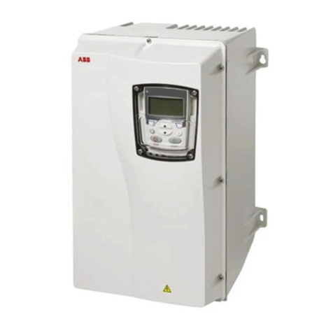
Welcon WER-D048-FS00FD Series User manual

(15434) Room 812, 555, Byeolmang-ro, Danwon-gu, Ansan-si, Gyeonggi-do, Republic of Korea PHONE +82 31 417 6735 FAX +82 417 6736
www.welconsystems.com
WELCON
Servo Drive
Hardware Manual
WER_D048_xx_FS00FD_x

WELCON Servo Drive Hardware Manual
2 / 24
© 2022 WELCON Systems. All rights reserved.
www.welconsystems.com
Precautions
- Please read this manual carefully before installing and commissioning.
- WELCON SYSTEMS assumes no responsibility whatsoever for any loss or damage arising
out of use for any purpose.
Copyright Notice
© 2022 WELCON Systems. All rights reserved.
Copyright in this document is reserved exclusively by WELCON SYSTEMS. That is, the
owner of the text, images, and all other materials listed in this document is WELCON
SYSTEMS. Therefore, the unauthorized distribution, transfer, or duplication of the text,
images, and other materials in this document without the written permission of the
copyright holder, WELCON SYSTEMS, is prohibited.

WELCON Servo Drive Hardware Manual
3 / 24
© 2022 WELCON Systems. All rights reserved.
www.welconsystems.com

WELCON Servo Drive Hardware Manual
4 / 24
© 2022 WELCON Systems. All rights reserved.
www.welconsystems.com
CONTENTS
Precautions ..................................................................................................................................................................... 2
Copyright Notice ......................................................................................................................................................... 2
CONTENTS................................................................................................................................................ 4
1. Safety Information ......................................................................................................................... 5
Use environment ......................................................................................................................................................... 6
2. Technical Information .................................................................................................................... 7
2.1. Mechanical Data .................................................................................................................................................. 7
2.2. Electrical Data ....................................................................................................................................................... 8
3. Wiring ............................................................................................................................................. 10
3.1. Tools ....................................................................................................................................................................... 10
3.2. Connections ........................................................................................................................................................ 10
3.3. Regenerative resistance ................................................................................................................................. 11
3.4. Main Power ......................................................................................................................................................... 12
3.5. Motor UVW ......................................................................................................................................................... 13
3.6. Analog Encoder ................................................................................................................................................. 14
3.7. Serial Encoder .................................................................................................................................................... 15
3.8. Digital Encoder .................................................................................................................................................. 16
3.9. GPIO ....................................................................................................................................................................... 19
3.10.EtherCAT ............................................................................................................................................................. 21
3.11.CAN ....................................................................................................................................................................... 22
3.12.USB ........................................................................................................................................................................ 22
Question : www.welconsystems.com

WELCON Servo Drive Hardware Manual
5 / 24
© 2022 WELCON Systems. All rights reserved.
www.welconsystems.com
1. Safety Information
Safety accidents and damage to the product may occur, so be sure to read the safety
instructions before use and use it correctly.
⚠ Warnings
- 전원이 켜진 상태에서 서보 드라이브 주 전원을 연결/분리하지 마십시오.
Do not connect/disconnect the main power of the servo drive while the power is on.
- 전원이 켜진 상태에서 서보 드라이브 엔코더 케이블 및 I/O를 연결/분리하지 마십시오.
모터 및 서보 드라이브의 고장 원인이 될 수 있습니다.
Do not connect/disconnect the servo drive encoder cable and I/O while the power is
on. Motor and servo drive may be damaged.
- 전원 케이블은 모터가 움직이지 않을 때도 고전압을 전달할 수 있습니다.
The power cable can carry high voltage even when the motor is not moving.
- 서보 드라이브의 메인 전원은 드라이브 사양에 맞춰 정확히 입력되어야 합니다.
드라이브 파손 및 고장의 원인이 될 수 있습니다.
The main power of the servo drive must be accurately input according to the drive
specifications. It may cause damage to the drive
- 서보 드라이브 U, V, W 출력 단자에 전원을 직접 접속하지 마십시오.
Do not connect power directly to the servo drive U, V, W output terminals.
- 서보 드라이브 전원을 차단 한 후 캐패시터가 완전히 방전된 후 전원을 분리해 주십시
오.
After turning off the servo drive power, disconnect the power after the capacitor is
completely discharged.

WELCON Servo Drive Hardware Manual
6 / 24
© 2022 WELCON Systems. All rights reserved.
www.welconsystems.com
⚠ Cautions
- U, V, W 케이블과 Encoder 케이블은 반드시 분리하여 배선해 주십시오.
Be sure to separate U, V, W cables and encoder cables before wiring.
- 전원 차단 후 U, V, W 케이블과 Encoder 케이블 배선작업을 진행하십시오.
After turning off the power, proceed with wiring the U, V, W cables and encoder cables.
- 떨어뜨리거나 강한 충격을 가하지 마십시오.
Do not drop it or subject it to strong impact.
- 가연성 물질, 물 근처는 설치를 하지 말아주십시오.
Do not install near flammable substances or water.
- 서보 드라이브 내부에 피복이나 구리선 등이 들어가지 않도록 해 주십시오.
Make sure that no sheath or copper wire gets inside the servo drive.
- Encoder 케이블은 쉴드 케이블 사용을 권장합니다.
It is recommended to use shielded cables for encoder cables.
- EtherCat 케이블은 CAT.7 이상의 케이블 사용을 권장합니다.
For EtherCat cables, it is recommended to use CAT.7 cables.
- 초기 전원 투입 전 모터의 U, V, W 및 Encoder 케이블 등을 확인하여 주십시오.
Check the U, V, W and encoder cables of the motor before turning on the power.
- 노이즈 방지를 위해 Encoder 케이블 및 U, V, W 및 전원 FG 접속을 권장합니다.
It is recommended to connect the encoder cable and U, V, W and power FG to prevent
noise.
Use environment
환경 조건
Operating Temperature 0
°C to 50 °C
Maximum Humidity 90[%] RH
Operating Place A place free of iron, flammable gas, dust, etc.

WELCON Servo Drive Hardware Manual
7 / 24
© 2022 WELCON Systems. All rights reserved.
www.welconsystems.com
2. Technical Information
2.1. Mechanical Data
Item Unit Description
Weight g 296
SIZE (L x W x H) mm 109.5 * 73.5 * 31
Fastener M3
*For details, please refer to the 3D Modelling on the homepage.

WELCON Servo Drive Hardware Manual
8 / 24
© 2022 WELCON Systems. All rights reserved.
www.welconsystems.com
2.2. Electrical Data
WER-D048/xx-FS00FD-x
Ratings 5 10
Continuous Output Current A rms 5 10
Peak Output Current A rms 10 20
Basic Specifications
Feature Specification
Motors DC/BLDC/PMSM/VCM Rotary servo motors, Linear servo motors
Current(Torque)
Control
Control Periodic 24KHz
Control Loop PI + Feed-forward
Velocity & Position
Control
Control Periodic 2KHz
Control Loop Cascade P/PI + Feed-forward
Filters First order low pass filter, Four notch filters,
First order adaptive windowing filters.
Reference Command
Current/Velocity/Position
USB + CANopen or EtherCAT(CoE, FoE)
Auto Tuning Method
Automatic self-configuration and
optimization of motor phasing, wires,
current loop, velocity control loop.
GUI User Interface WELSS(WelconServoStudio), Setting, Drive,
Motor, Feedback, I/O, Motion
Input Voltage 12~48VDC
Protective Functions Under- and over-voltage, Over-current, Over-load(with I
2
T), Drive over-
temperature
Compliance Standard
CE, KC
Environment
Ambient temperature: Operation 0-50℃, Storage 0-70℃
Humidity: 10-90%
Vibration: 1.0g
Communication
Feature Specification
CAN
CANopen – CiA 301 application layer and CiA 402 device profile for
drives and motion control.
Bit rate : 125kbps ~ 1Mbps

WELCON Servo Drive Hardware Manual
9 / 24
© 2022 WELCON Systems. All rights reserved.
www.welconsystems.com
EtherCAT
CiA 301 application layer and CiA 402 device profile for drives and
motion control
Communication cycle time: up to 500μs(CSV, CSP mode), up to
250us(CST mode)
USB Baud rate : up to 3Mbps
Maximum cable length 3m
I/O
Feature Specification
Analog Input
Quantity 1
Voltage Range Analog ±10 VDC differential
Input Resolution 14 bit
Digital Input
Quantity 6 (with STO)
Signal Configurable. Opto-isolated
Voltage 24V
Digital Output
Quantity 2
Signal Configurable. Opto-isolated. Open collector
Voltage 24V
Max. Output Current 35mA
Motor Feedback
General Supply Voltage 5VDC
Incremental Encoder
Signal A-quad-B with or without index, shared digital
hall sensor, RS422, Differential
A-quad-B Max Input
Frequency 10MHz (before quadrature)
Digital Hall Sensor Signal Differential
Type Separated and shared hall sensor
Analog Hall Sensor
Signal 0~5V, Single-ended
Sampling Frequency 24KHz
Interpolation 14 bit
Sin/Cos Encoder
Signal -0.7~+0.7V at 2.5V, Differential
Sampling Frequency 24KHz
Interpolation 14 bit
Serial Encoder Type SSI, Biss-C, Tamagawa, Panasonic
Bite rate 0.5Mbps, 1Mbps, 2Mbps, 2.5Mbps, 5Mbps

WELCON Servo Drive Hardware Manual
10 / 24
© 2022 WELCON Systems. All rights reserved.
www.welconsystems.com
3. Wiring
3.1. Tools
Tool Manufacturer Part Number
Hand crimp Tool MOLEX 63811-6300
3.2. Connections
W1 → Regenerative resistance
W2 → Main Power
W3 → Motor UVW
W4 → Analog Encoder
W5 → Digital Encoder
W6 → Serial Encoder
W7 → GPIO
W8 → USB
W9 → EtherCAT Output
W10 → EtherCAT Input
Table of contents
Other Welcon Servo Drive manuals
Welcon
Welcon WER-D048/25-FS0005-C User manual
Welcon
Welcon WEC-D048/08-FS0025-E User manual
Welcon
Welcon WE2A D048 Series User manual
Welcon
Welcon WER-D048 Series User manual
Welcon
Welcon WEC-D048/25-FS002D-E User manual
Welcon
Welcon WE2S D024 FS0057 Series User manual

Welcon
Welcon WEM D048 Series User manual


