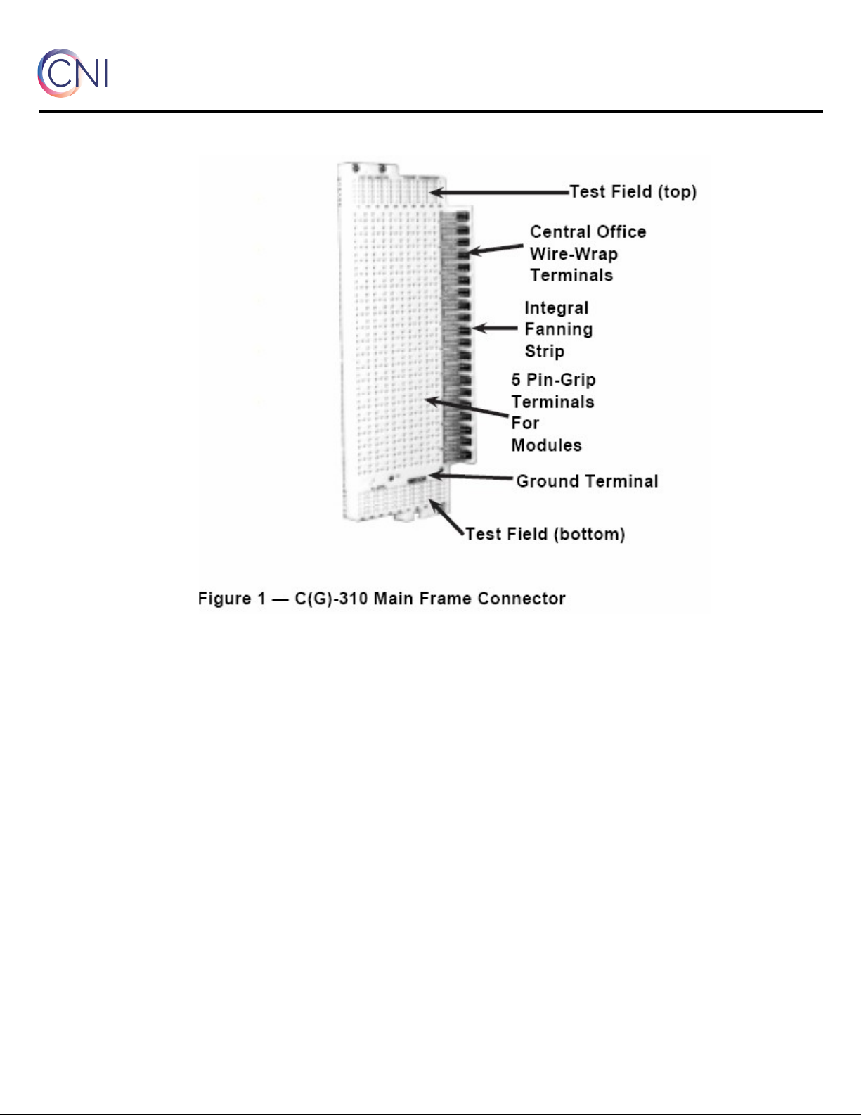
C (G)-310 Main Frame Connector
comtestnetworks.com
5. Grounding
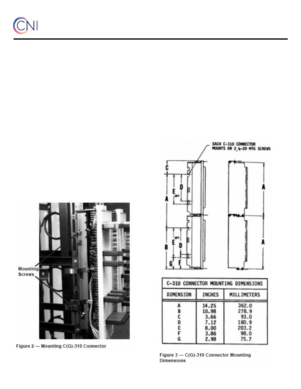
5.1 Three methods may be used to connect the C–
310 connector to electrical ground. The connector
ground wiring is terminated at a no. 10 ground
screw terminal on the rear of the connector base
(Figure 4). This ground screw is jumpered to the
lower portion of the connector mounting bracket
through a short (3-1/2-inch) ground strap. The
grounding methods are described in the following
paragraphs.
5.2 Basic grounding method: Use the 7 3/4-
inch interconnector ground strap supplied with the
unit to connect the 1/4-20 mounting screws on
adjacent connectors (see I Basic, Figure 5).
Repeat this procedure for each pair of connectors
on the same vertical. Connect the bottom 1/4-20
mounting screw on the lowest connector to a 1/4-
20 terminal on the main frame copper ground bar
using the long (26 1/2- inch) ground strap.
5.3 Independent ground method: Use the
interconnector ground strap (17 1/2 inches long) to
connect the no. 10 ground screw terminals of each
pair of adjacent connector bases on the same
vertical (see II Independent, Figure 5 ). Connect
the no. 10 ground screw ground terminal on the
lowest connector to the 1/4-20 terminal on the
main frame copper ground bar using the long (28-
inch) ground strap.
5.4 Isolated ground method: Remove the short
(3 1/2-inch) ground strap from the no. 10 screw
ground terminal and the connector mounting
bracket. Use the interconnector ground strap (17
1/2-inch) to connect the no. 10 screw ground
terminals of each pair of adjacent connector bases
on the same vertical (see III Isolated, Figure 5).
Connect the no. 10 screw ground terminal on the
lowest connector to the 1/4 -20 terminal on the
main frame copper ground bar using the long
(28-inch) ground strap.
Note: The long ground straps, 26 1/2-inch and 28-
inch, and the interconnector ground strap, 17 1/2-
inch, are accessory items and must be ordered
separately.
5.5 Tighten all mounting screws after all of the
connectors and ground straps are placed in
position on the vertical mounting bar.
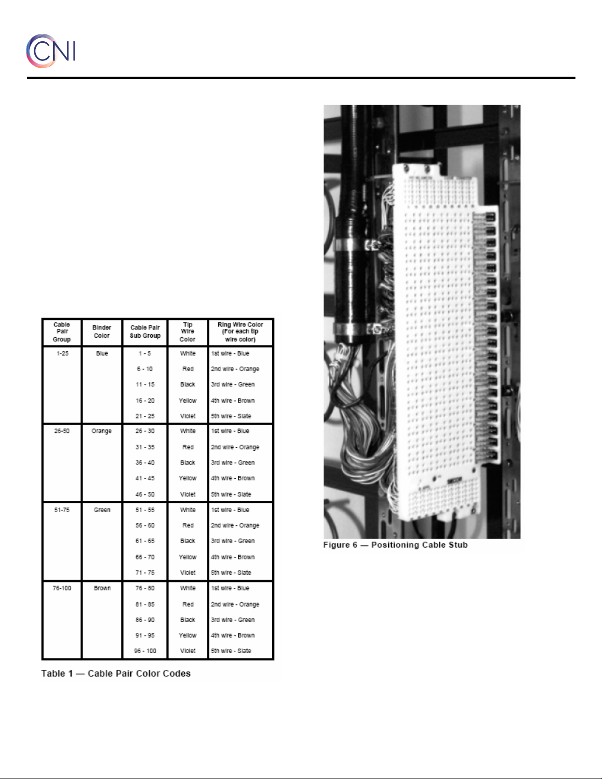
5.6 The clamps on the pressure plug of the
connector stub should be carefully bent to the
vertical mounting bar, so the stub cable will be out
of the way for future work at the frame (Figure 6).
5.7 The stub cables of all connectors on a
vertical mounting bar should be neatly arranged
against the transverse arms of the frame. Lash the
stub to these transverse arms in a neat manner.
5.8 Close the cable entrance slots, or ferrules, in
the floor, in accordance with local instructions.