CO-Z SGO-0000-01 User manual

Sliding Gate Opener
User Manual
Read Carefully Before Use
Keep for Future Reference
V20231201
SGO-0000-01 1400 lb. Complete Kit
SGO-EC06-02 1400 lb. Essentials Kit
SGO-1801-GY 1800 lb. Home Use Kit


PLEASE READ THIS FIRST
Thank you for purchasing our sliding gate opener.
This manual only applies to the following CO-Z®products.
This manual provides the knowledge needed to safely and eciently operate this product and
manufacturer-licensed accessories. Contact customer service if you have any questions.
Read this manual carefully before installation and use. Follow this manual completely, paying
particular attention to safety instructions. Failure to do so may cause serious personal injury and
product damage.
This product was exclusively designed and manufactured for the use specied in this manual.
Any use not specified herein could potentially damage the product and pose risks. Incorrect
installation or improper use of the product may result in harm to individuals, animals, or property.
This manual describes the congurations, options, and accessories of this product.
This manual contains crucial specifications, precautions, and troubleshooting information
necessary to ensure safe and eective use of this product. Keep this manual in an easily
accessible location and store it securely.
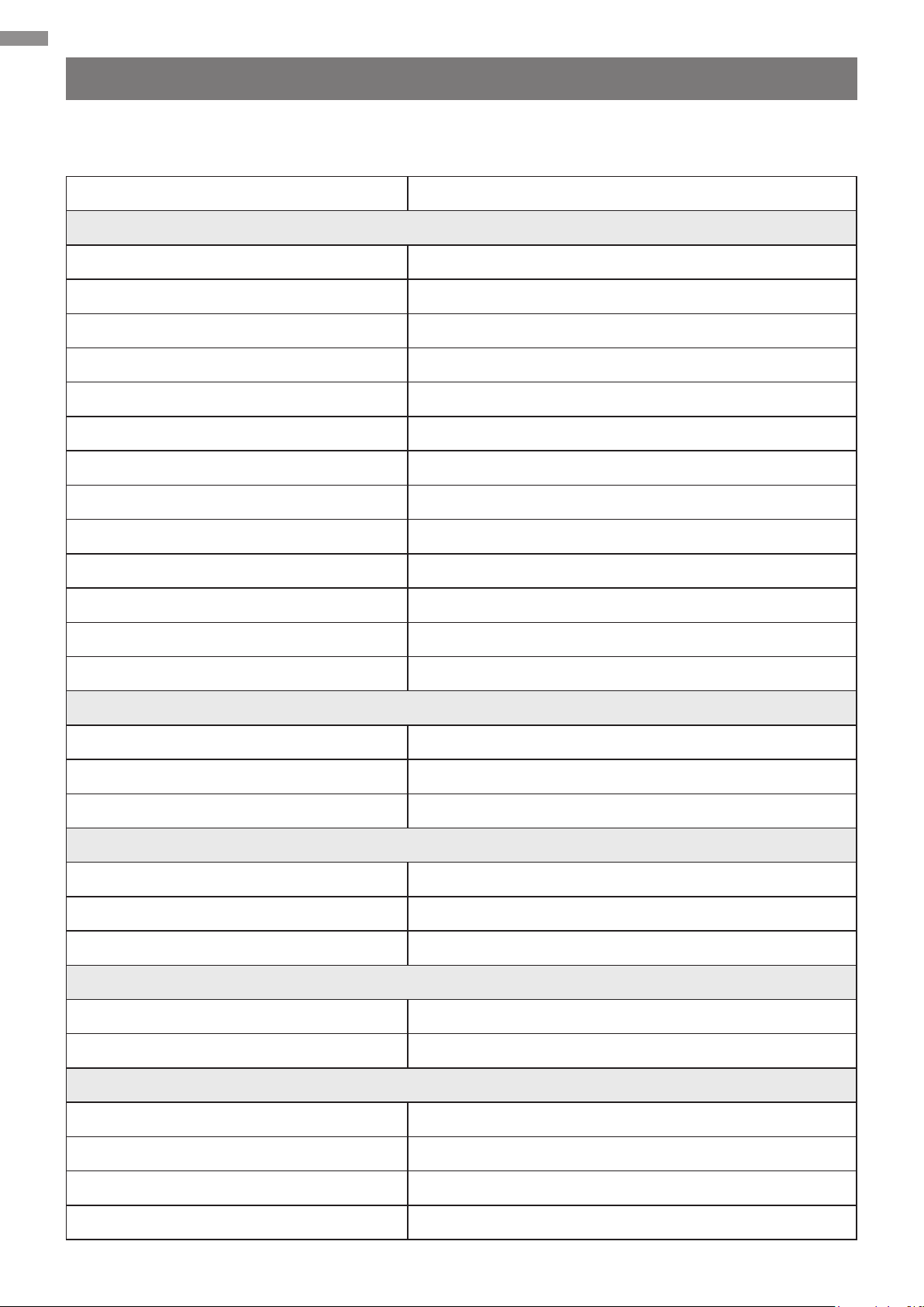
Name Model
Sliding Gate Opener 1400 lb.
Sliding Gate Opener 1400 lb. Essentials Kit
Sliding Gate Opener 1800 lb. Home Use Kit
SGO-0000-01
SGO-EC06-02
SGO-1801-GY

Audience
This manual is intended for adult readers who are capable of independent behavior and
autonomy and who possess a basic awareness of mechanical and electrical safety precautions.
Users must be fully aware of the mechanical and electrical risks that may be involved in the
installation and use of such products before use.
Symbol Guide
The following symbols are used in this manual:
Symbol Meaning
Warning
Precautions to prevent serious property damage or personal injury
Caution
Precautions to prevent damage to equipment and facilities
Note
Crucial information that can contribute to safer and more ecient usage

FOR YOUR RECORDS
You can record the following information for future reference in case you require service
for your automatic gate opener.
Model:
Date of Purchase:
Place of Purchase:

Contents
1. General Safety Information..................................................................................................1
2. Product Description .............................................................................................................2
2.1 Specications ...................................................................................................................2
SGO-0000-01 ...............................................................................................................................................3
SGO-EC06-02 ..............................................................................................................................................5
SGO-1801-GY..............................................................................................................................................7
2.2 Package List.....................................................................................................................9
Main Components ........................................................................................................................................9
Base Components........................................................................................................................................9
Chain Support Components .......................................................................................................................10
Magnetic Limit Switch Components ........................................................................................................... 11
Infrared Sensor (SGO-1801-GY Only) ....................................................................................................... 11
Optional Accessories for Function Expansion ............................................................................................12
3. Preparation..........................................................................................................................13
3.1 Denition of Sliding Direction..........................................................................................13
3.2 Check Installation Conditions .........................................................................................14
3.3 Customize Your Installation ............................................................................................14
3.4 Prepare Components and Tools.....................................................................................15
4. Install Safety Guards..........................................................................................................16
5. Mechanical Installation ......................................................................................................17
5.1 Safety Precautions .........................................................................................................17
5.2 Base Component Assembly ...........................................................................................18
5.3 Base-Main Unit Connection............................................................................................18
5.4 Chain Installation............................................................................................................19
5.5 Chain Test.......................................................................................................................24
5.6 Chain Box Cover Reinstallation......................................................................................24
6. Electrical Component Installation.....................................................................................25
6.1 Important Information ....................................................................................................25
6.2 Circuit Connection Methods ...........................................................................................25
6.3 Control Board Description ..............................................................................................26
Overview.....................................................................................................................................................26
Indicator Lights ...........................................................................................................................................27
Control Buttons...........................................................................................................................................28
Digital Display.............................................................................................................................................28
Interfaces....................................................................................................................................................29

6.4 System Powering............................................................................................................30
6.5 Direction Reversal ..........................................................................................................30
6.6 Limit Switch Magnets......................................................................................................31
6.7 Fixation...........................................................................................................................32
6.8 Infrared Equipment Connection (SGO-1801-GY Only) ..................................................34
6.9 Wire Connection Guidance of Optional Accessories......................................................35
Warning Light .............................................................................................................................................35
Push Button................................................................................................................................................35
Swipe Card, Digital Keypad, and Other External Devices..........................................................................35
Loop Detector.............................................................................................................................................36
7. Operation.............................................................................................................................37
7.1 Remote Control Description ...........................................................................................37
7.2 Functions........................................................................................................................37
Movement Limitation ..................................................................................................................................37
Mechanical Obstruction Feedback .............................................................................................................37
Infrared Obstruction Feedback...................................................................................................................38
Automatic Closing.......................................................................................................................................38
Pedestrian Mode ........................................................................................................................................38
Vehicle Detection........................................................................................................................................38
Travel Learning...........................................................................................................................................38
Motor Running Protection...........................................................................................................................39
Manual Mode..............................................................................................................................................39
7.3 Code Display ..................................................................................................................39
7.4 Basic Function Conguration..........................................................................................40
Accessing the Setting Menus .....................................................................................................................40
Selecting Menus and Adjusting Values.......................................................................................................40
Conrming Selections and Saving Changes ..............................................................................................40
Exiting the Setting Menus...........................................................................................................................40
7.5 Advanced Function Conguration...................................................................................40
Learning Codes (Remote Control Learning)...............................................................................................40
Clearing Codes...........................................................................................................................................40
Travel Learning...........................................................................................................................................41
Parameter Adjustment................................................................................................................................41
8. Troubleshooting .................................................................................................................43
9. Maintenance........................................................................................................................46
10. Disposal.............................................................................................................................48
11. Contact Information..........................................................................................................48

1
1. General Safety Information
Read the following information carefully before installation and use. This section provides general
safety precautions. For particular precautions, consult the dedicated operation instructions related
to those tasks.
Caution
• Any actions or elements not explicitly covered in these instructions are strictly prohibited.
• ALWAYS keep bystanders, pets, and any objects away from the automation operation
area.
• NEVER cross the path of the gate while it is in motion. Even driving through when it is
closing remains EXTREMELY dangerous.
• NEVER let children operate or play with the gate controls and keep control devices out of
the reach of children to prevent unintentional automation activation.
• DO NOT initiate the gate opener unless you have a clear line of sight and can conrm that
its pathway is clear of people, pets, or other obstructions. Maintain constant vigilance over
the gate's entire range of motion.
• NEVER modify the automation components without explicit authorization from the
factory. NEVER attempt to perform repairs on the automotion system. NEVER replace
any components with nonidentical ones. Making modications or adding components by
personnel without proper training or involving unauthorized parts will void the manufacturer's
warranty. Seek professional assistance from qualied technicians if needed.
• Maintain the gate opener as instructed herein. ALWAYS unplug the gate opener before
performing any inspection, servicing, or maintenance.
• Dispose of the packing materials (incl. plastic, cardboard, polystyrene, etc.) in accordacne
with local and national laws and regulations.
• Keep nylon or polystyrene bags out of the reach of children.
Warning
General Safety Information

2
Product Description
2. Product Description
Designed for installation on a slide-to-open single leaf gate, this opener system autonomously
manages gate control for seamless vehicle entry and exit from your property. This operator
accommodates a range of accessories, which are outlined in Optional Accessories below.
Equipped with a safety feature, this operator halts and reverses gate movement upon encountering
an obstruction. Additionally, an adjustable auto-close feature is included. The system boasts
eortless installation and setup, requiring minimal maintenance to ensure optimal performance.
Warning
This product is not intended for the containment of animals.
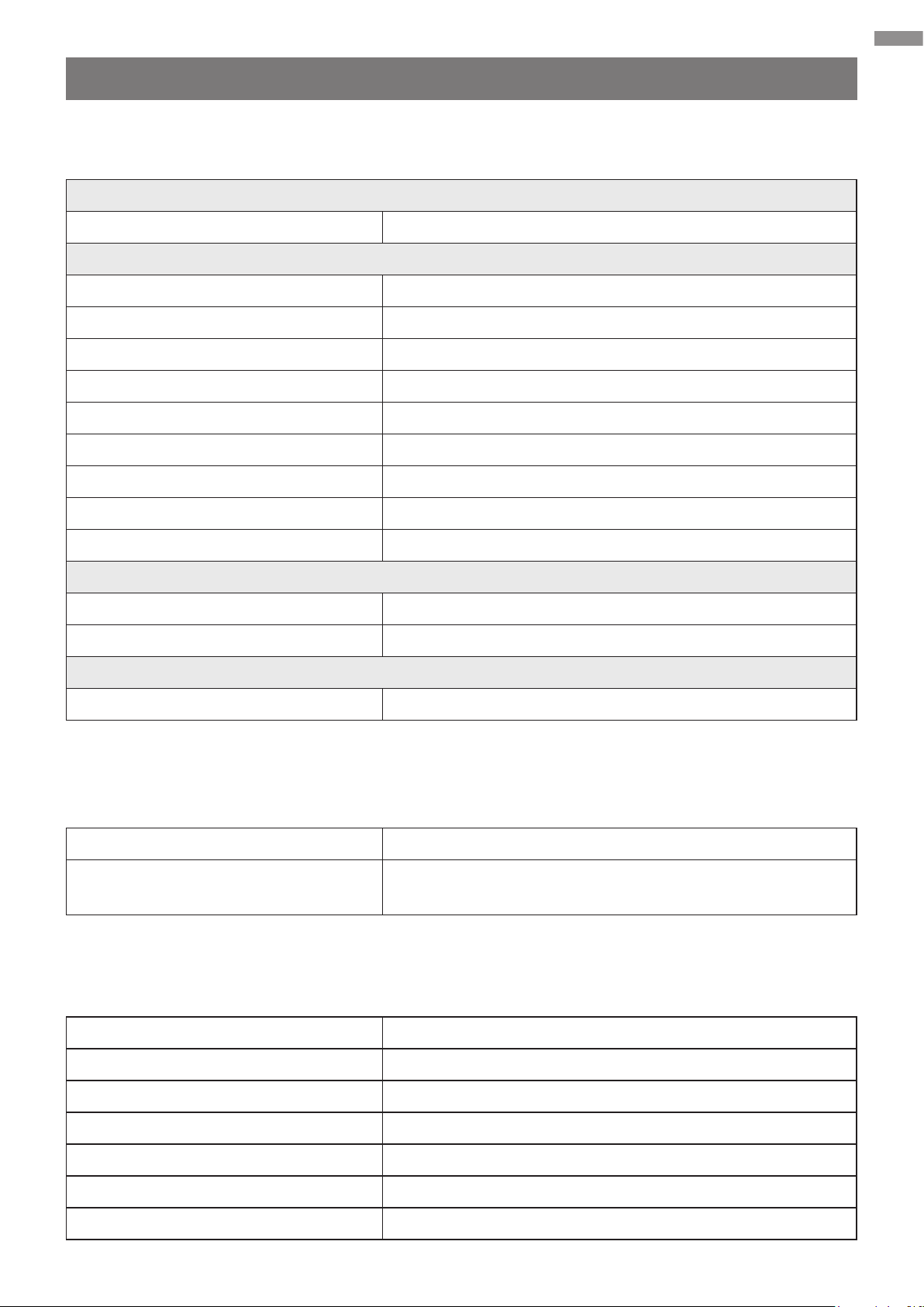
2.1 Specications
This manual covers the following three models of sliding gate openers. For accurate information,
read the content corresponding to the model you have purchased.

3
Product Description
Main Unit
Input Voltage & Freq. 110 V AC 60 Hz
Components
Motor Type Alternating Current (AC)
Motor Coil Material Copper
Brushed/Brushless Motor Single-Phase Induction Motor
Rated Voltage 110 V AC
Rated Current 2.5 A
Rated Power 220 W
Torque 22 N·m
Motor Speed 1500 rpm
Gear Speed 62 rpm
Housing Material Acrylonitrile Butadiene Styrene (ABS)
Motor Base Material Cast Aluminum
Duty Cycle S2, 20 min.
Noise Level < 56 dB
Gear Shaft
Gear Material Steel
Turbine Material Copper
Worm Material Steel
Gate Compatibility
Max. Width 40 ft. (12.2 m)
Max. Weight 1400 lb. (635 kg)
Sliding Speed 3.3 fpm (13 m/min.)
Operational Environment
Ambient Temperature −4 to 158°F (−20 to 70°C)
Weatherproof Rating IP44
Remote Control
System Capacity 120 Remotes
Frequency 433.92 MHz (Rolling Code)
Eective Range 54.7 yd. (50 m)
Gate Control Modes Remote, Manual
SGO-0000-01

4
Product Description
Functions
Motor
Thermal Cuto Yes
Gate Operation
Operating Time 60 sec.
Sliding Speed Yes
Slow Start Time No
Slow Stop Time Yes
Obstacle Stop/Reversal Opening: Obstacle Stop / Closing: Obstacle Reversal
Auto-Close Timer Range 0–99 sec.
Sliding Direction Yes
Pedestrian Mode Yes
Limit Switch Type Magnetic Steel
Notication
Opening/Closing Digital Display Notication
Obstacle Reversal Limit Return
Remote Control
Button Conguration Single-Button/Three-Button Control
Size and Weight
Product Dimensions 14.2×11.2×18.7 in. (36×28×55.5 cm)
Product Net Weight
(Including Accessories) 15.2 kg
Accessories
Control Box Type Built-in
Remote Control Quantity 2
Manual Key Quantity 2
Fuse Type 10 A
Chain Length 9.8 in. (3 m) ×2
Installation Accessories Yes
Installation Accessory Material Silver-Plated Zinc Steel
SGO-0000-01
5
Product Description
Input Voltage & Freq. 110 V AC 60 Hz
Components
Motor Type Alternating Current (AC)
Motor Coil Material Aluminum
Brushed/Brushless Motor N/A
Rated Voltage 110 V AC
Rated Current 2 A
Rated Power 270 W
Torque 14 N·m
Motor Speed 1400 rpm
Gear Speed 54 rpm
Housing Material Acrylonitrile Butadiene Styrene (ABS)
Motor Base Material Cast Aluminum
Duty Cycle S2, 20 min.
Noise Level < 56 dB
Gear Shaft
Gear Material Steel
Turbine Material Nylon
Worm Material Steel
Gate Compatibility
Max. Width 40 ft. (12.2 m)
Max. Weight 1400 lb. (635 kg)
Sliding Speed 3.3 fpm (13 m/min.)
Operational Environment
Ambient Temperature −4 to 158°F (−20 to 70°C)
Weatherproof Rating IP44
Remote Control
System Capacity 120 Remotes
Frequency 433.92 MHz (Rolling Code)
Eective Range 32.8 yd. (30 m)
Gate Control Modes Remote, Manual
Main Unit
SGO-EC06-02
6
Product Description
Functions
SGO-EC06-02
Motor
Thermal Cuto Yes
Gate Operation
Operating Time 60 sec.
Sliding Speed Yes
Slow Start Time No
Slow Stop Time Yes
Obstacle Stop/Reversal Opening: Obstacle Stop / Closing: Obstacle Reversal
Auto-Close Timer Range 0–99 sec.
Sliding Direction Yes
Pedestrian Mode Yes
Limit Switch Type Magnetic Steel
Notication
Opening/Closing Digital Display Notication
Obstacle Reversal Limit Return
Remote Control
Button Conguration N/A
Size and Weight
Product Dimensions 14.2×11.2×18.7 in. (36×28.5×47.5 cm)
Product Net Weight
(Including Accessories) 15.2 kg
Accessories
Control Box Type Built-in
Remote Control Quantity 2
Manual Key Quantity 2
Fuse Type 10 A
Chain Length 9.8 in. (3 m) ×2
Installation Accessories Yes
Installation Accessory Material Silver-Plated Zinc Steel

7
Product Description
Main Unit
Input Voltage & Freq. 110 V AC 60 Hz
Components
Motor Type Alternating Current (AC)
Motor Coil Material Copper
Brushed/Brushless Motor Single-Phase Induction Motor
Rated Voltage 110 V AC
Rated Current 2.8 A
Rated Power 180 W
Torque 26 N·m
Motor Speed 1500 rpm
Gear Speed 62 rpm
Housing Material Acrylonitrile Butadiene Styrene (ABS)
Motor Base Material Cast Aluminum
Duty Cycle S2, 20 min.
Noise Level < 56 dB
Gear Shaft
Gear Material Steel
Turbine Material Copper
Worm Material Steel
Gate Compatibility
Max. Width 40 ft. (12.2 m)
Max. Weight 1800 lb. (816.5 kg)
Sliding Speed 3.3 fpm (13 m/min.)
Operational Environment
Ambient Temperature −4 to 158°F (−20 to 70°C)
Weatherproof Rating IP44
Remote Control
System Capacity 120 Remotes
Frequency 433.92 MHz (Rolling Code)
Eective Range 54.7 yd. (50 m)
Gate Control Modes Remote, Manual
SGO-1801-GY

8
Product Description
Functions
SGO-1801-GY
Motor
Thermal Cuto Yes
Gate Operation
Operating Time 60 sec.
Sliding Speed Yes
Slow Start Time No
Slow Stop Time Yes
Obstacle Stop/Reversal Opening: Obstacle Stop / Closing: Obstacle Reversal
Auto-Close Timer Range 0–99 sec.
Sliding Direction Yes
Pedestrian Mode Yes
Limit Switch Type Magnetic Steel
Notication
Opening/Closing Digital Display Notication
Obstacle Reversal Limit Return
Remote Control
Button Conguration Single-Button/Three-Button Control
Size and Weight
Product Dimensions 14.2×11.2×18.7 in. (36×28.5×47.5 cm)
Product Net Weight
(Including Accessories/Infrared Sensor) 15.25 kg
Accessories
Control Box Type Built-in
Remote Control Quantity 2
Manual Key Quantity 2
Fuse Type 10 A
Chain Length 9.8 in. (3 m) ×2
Installation Accessories Yes
Installation Accessory Material Silver-Plated Zinc Steel
Wired Infrared Sensors 1 Pair (2 Units)

9
Product Description
2.2 Package List
Item Name Qty. Image
1Main Unit 1
2Chain Box Cover 1
3Chains 2
4Manual Keys 2
Main Components
Item Name Qty. Image
1Base Frame 4-in-1
2 M6×20 Hex Bolts 4
3 M6 Hex Nuts 4
4M6 Spring Washers 4
Base Components

10
Product Description
Item Name Qty. Image
5 M6 Flat Washers 4
6 M10×45 Hex Bolts 4
7 M10 Flat Washers 4
8M10 Spring
Washers 4
9M10×80 Anchor
Bolts 4
Base Components (Continued)
Item Name Qty. Image
1Arched U-Bolts 4
2Square U-Bolts 4
3 M6 Hex Nuts 8
4 M6 Flat Washers 8
5M6 Spring Washers 8
6Chain Brackets 2
Chain Support Components

11
Product Description
Item Name Qty. Image
7 M8 Bolts 2
8 M8 Hex Nuts 4
9 M8 Flat Washers 4
10 M8 Spring Washers 4
11 Chain Joints 2
Chain Support Components (Continued)
Name Qty. Image
Limit Switches
(Incl. one M8 Nuts &
two ST6×25 Screws)
2
Name Qty. Image
Infrared Sensor Set
(Incl. Installation Accessories) 1
Magnetic Limit Switch Components
Infrared Sensor (SGO-1801-GY Only)

12
Product Description
Optional Accessories for Function Expansion
• Warning Lights (Powered by AC)
• Push Button
• Swipe Card
• Digital Keypad
• Loop Detector (Ground Sensor)
Warning
Using components from other suppliers
will void the manufacturer’s responsibility
in regard to the automation safety and
proper operation.

13
Preparation
3. Preparation
This chapter describes the preparation work that needs to be done before installation. Please
carefully read and follow the instructions. Failure to do so may cause unsuccessful installation,
shorten the lifespan of your gate, or even result in personal injury and property damage.
3.1 Denition of Sliding Direction
Sliding direction herein refers to the direction in which your gate slides when you are facing the
gate and standing at the side of your gate opener. This device is designated for immediate use with
gates that slide open to the right. The installation procedures for gates that slide open to the left are
basically the same as that for gates that slide open to the right, except for installation procedure
with respect to the electrical part. Refer to Chapter 6 for details.
Right-Slide Opening
Left-Slide Opening
Warning
NEVER install this product in an explosive atmosphere.
This manual suits for next models
2
Table of contents


