CoachComm Tempest NG Sideline User manual

v1.2013
®
®
Sideline Communications System
User Manual

Thank you from CoachComm!
We at CoachComm want to thank you for purchasing a Tempest NG Sideline Communications System. We have made every
effort to build a reliable, intuitive communication system that provides the functionality that you can count on come gameday.
One of our goals in the design of the Tempest NG System was to build on the advances set forth by the previous NG Series
System and to provide users with unmatched RF performance. You will be able to begin using your new Tempest NG System
with nothing more than the Quick Start Guide. However, to fully benet from the available features, please read this manual
carefully.
We wantTempest NG to make your job easier and your gameday experience to be positive. To successfully familiarize yourself
with the many diverse and powerful features Tempest NG offers, it is crucial that you acquaint yourself with the manual. Your
time spent will help you get the most from yourTempest NG System by making setup quick and easy.
We are committed to providing you with a high quality product that will deliver years of trouble free service. Should you
experience any problem with yourTempest NG equipment, whether it is under warranty or not, we will be there to take care of
your needs.
Thank you for choosing CoachComm for your sideline communication needs.

© 2013 CoachComm LLC. All rights reserved.
Tempest NG andTempest NG900 Sideline Communications User Manual Rev1.2013
COACHCOMM, LLC
Tempest NG
205Technology Parkway
Auburn, AL 36830
Phone: 334-321-2300
Fax: 888-329-2658
www.coachcomm.com
Tempest® is a registered trademark of CoachComm, LLC.
©Telex is a registered trademark ofTelex Communications, Inc.
©Audiocom is a registered trademark of Bosch Security Systems, Inc.

Table of Contents
Introducon...................................................................................................................................... 1
A/C Power Warning.......................................................................................................................... 2
FCC Informaon ............................................................................................................................... 2
What makes Tempest so dierent?.................................................................................................. 3
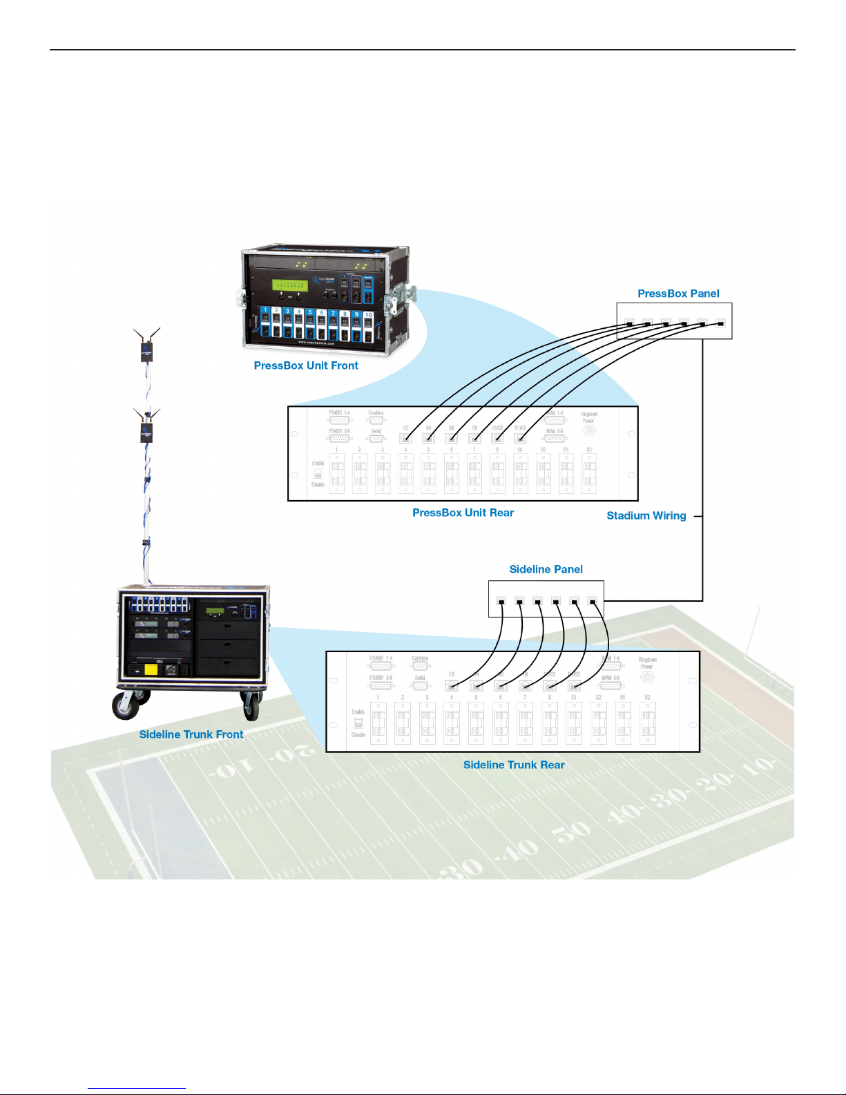
Block Diagrams ................................................................................................................................. 5
TNG System Block Diagram.............................................................................................................. 5
Sideline Unit Block Diagram............................................................................................................. 6
Pressbox Unit Block Diagram .......................................................................................................... 7
Components ..................................................................................................................................... 9
The Sideline Unit .............................................................................................................................. 9
The Pressbox Unit .......................................................................................................................... 10
WIM 8(RD) Wired Interface Module .............................................................................................. 11
WIM 8(RD) Integrated Dry Pair Tester (DPT) ..................................................................................12
WIM 8(RD) Screens ........................................................................................................................ 13
Flexible Combine Module (FCM)....................................................................................................14
Ringdown Circuits .......................................................................................................................... 14
WAM 10 Wired Assignment Module..............................................................................................15
The BP 1002 / BP 2002 Beltpacks (AudioCom® by Telex®).............................................................16
Headsets ........................................................................................................................................ 17
Power Supply ................................................................................................................................. 17
Wireless BaseStaon...................................................................................................................... 19
Wireless Remote Transceiver ......................................................................................................... 21
BaseStaon Menu System..............................................................................................................23
Wireless BeltPack ........................................................................................................................... 37
BeltPack Baery System................................................................................................................. 38
BeltPack Menu System................................................................................................................... 39
Antenna System ............................................................................................................................. 46
Game Day Setup .............................................................................................................................47
On The Sideline .............................................................................................................................. 47
In The Pressbox .............................................................................................................................. 48
Wireless Component Set Up and Integraon.................................................................................49
Glossary..........................................................................................................................................54
Appendix A ....................................................................................................................................55
Update the Firmware (with CodeUpdater) ....................................................................................55
Appendix B .....................................................................................................................................56
Tempest NG Specicaons.............................................................................................................56
Appendix C .....................................................................................................................................58
Tempest NG900 Specicaons.......................................................................................................58

[This page intentionally left blank]

Tempest NG User Manual v1.2013 1
Introduction
Introduction
In 1991, CoachComm pioneered a new era in sideline communications and CoachComm’s wired systems were quickly recognized
as the best in the industry. Since 1997, CoachComm, LLC has been offering wireless products to meet the communications needs
of the football coaching market beginning with the UC series system. Based on the Telex® BTR/TR 600 digital radios, the UC
system became the standard for sideline communications for Division 1A football as well as for most professional teams.
While very popular, the UC system was limited with regards to its ability to perform in certain RF environments. Each system has
two (2) unique operating frequency sets, therefore a team can either be on frequency set “A” or set “B”. With the proliferation of
digital television broadcast signals in recent years, UC systems have experienced more RF interference from outside sources.
In addition to RF considerations, coaches were demanding increased audio quality, more wireless users, and several other
operational enhancements. Considering all of these factors and operational issues, CoachComm created the new NG series
system.
The CoachComm NG series system is an advanced, multi layered communication system for football coach communications.
NG addressed features not included in its predecessor, UC, with features such as frequency agility, an increased number of
wireless users, substantially better audio quality and a host of other renements.
Even though the NG series represented a huge improvement with issues surrounding user operation, complexity and continuing
problems within the frequency spectrum for Part 74 devices, CoachComm elected to develop a new sideline communications
system that was completely outside of the Part 74 FCC rules and that has enhanced user features and ease of use. The new
system is calledTempest NG. While the wireless portion of theTempest NG system is new technology, the central infrastructure
of theTempest NG system is identical to the previous NG system. Therefore, the nomenclature of “NG” was retained.
The wired portion of the Tempest NG Series system is designed around the Telex® AudioCom® platform. The AudioCom®
Platform is the only sports communications system that employs two very important audio concepts: the balanced line concept
and the transformer isolation concept.
The AudioCom® system uses a balanced line approach to signal transmission. This means that the system is more forgiving
on twisted pair and that it is not necessary to “balance” the dry pair as you have to do in unbalanced systems. This makes for
faster setup and easier conguration changes. The transformer isolation employed in AudioCom® BeltPacks is one of the most
important features of the wired system. This transformer, located in each BeltPack, isolates the user from potential sources of
noise in the dry pair. It may not isolate every noise, but it does remove the most annoying buzzes and crackles associated with
other systems.
Expandability and adaptability are keys to the Tempest NG system. Users can be put into and taken out of the system without
affecting other users. In other systems, taking a user out of the line may cause an increase in system volume or a change in
system impedance resulting in voice quality degradation. In the Tempest NG system, however, adding and removing users is
virtually transparent.
This is the most advanced intercom system in use today. We highly recommend that you thoroughly read and study this manual.
Concepts and practical hints on system setup will help you be more efcient in system administration.

2
Introduction
A/C Power Warning
User should exercise extreme care when working with electricity. Additional care should be used when working with electricity
outdoors in inclement weather. Keep all electrical connections internal to the system unit and plug the system only into a ground
fault interrupting circuit.
FCC Information
This unit has been tested and found to comply with the limits for a class A digital device, pursuant to part 15 of the FCC Rules.
These limits are designed to provide reasonable protection against harmful interference when the equipment is operated in
a commercial environment. This equipment generates, uses, and can radiate radio frequency energy, and if not installed and
used in accordance with the instruction manual, may cause harmful interference to radio communications. Operation of this
equipment in a residential area is likely to cause harmful interference, in which case, the users will be required to correct the
interference at their own expense. Commensurate with EIRP limits specied in FCC Rules 15.247b, this device may not be
used with antennas that exceed 9dB of gain in multi-point applications. For use in RF exposure mobile or xed conditions, the
antenna(s) used for this transmitter must be installed to provide a separation distance of at least 20 cm from all persons.
Transmitter Module FCCID: HSW-2492
or
Transmitter Module FCCID: HSW-934
FCC Regulations — CoachComm strongly urges our users of wireless products to research and where applicable pursue licensing
with the Federal Communications Commission. You may wish to seek qualied legal assistance to assist you in this process.
You should respect the fact that other frequency users in your area may have a legal right to the frequency you are using. FCC
regulations stipulate that the end user of this equipment is responsible for lawful use of this product.

Tempest NG User Manual v1.2013 3
Introduction
What makes Tempest so different?
CoachComm has been building wired systems for over 16-years and wireless systems for over 11-years to supply quality
communications to D-1A teams nationwide. Therefore, CoachComm’s knowledge of wireless technology in the D1A football
arena is vast and our experience is deep. When it came time to build the next generation of equipment to service that industry
– CoachComm was up to the challenge.
Tempest is so unique that it has taken not only the football world, but other wireless intercom applications by storm! Simply put,
Tempest is the world’s rst fully featured, 2.4 GHz, frequency hoping spread spectrum wireless intercom. Tempest now comes
in a 900 MHz model offering the same features.
Fully Featured
Tempest is the rst wireless intercom system to employ the feature set that end users demand. Some of the unique features
include:
»Durable industrial design
»No FCC license required
»No frequency coordination required
»Easy user set-up and operation
»Multiple battery options
»Call with vibrate
»Remote Mic Kill
»Unlimited number of BeltPacks
»Remote transceiver
»And much more..
These features come together to form an incredible product called Tempest. Tempest wireless is the heart of the Tempest NG
sideline communications system. Tempest wireless together with enhanced tools for the wired portion of the system make for
an incredibly robust, easy to operate system.
2.4 GHz
Previous NG and UC systems have operated in the FCC part-74 band. Over the past few years, the FCC has been relocating TV
stations from the old analog domain to the new digital era. As a part of this process, many of the frequencies used by the NG
and UC systems have either become over crowded or are no longer a legal option.
CoachComm designed the newTempest wireless product to operate in the 2.4 GHz frequency band. This band is open for general
use and does not require special licensing by the end-user. In addition, this band is specically set-aside by the FCC for devices
such asTempest that work well together even in a crowded RF spectrum. The idea is that devices constructed to work in this band
are supposed to work well even if there are other devices in this same frequency band.
900 MHz
In addition to the 2.4 GHz model, theTempest family of products now includes a 900 MHz model,Tempest NG900. The 900 MHz
model is a technologically-enhancing accessory to existing 2.4 GHz systems, giving users more options on game day. The user
inferface is exactly the same as the 2.4 GHz model, therefore no new training is required. This band is also a license-free band.
Frequency-Hopping Spread Spectrum
Frequency-Hopping Spread Spectrum (FHSS) is a means of RF transmission. In FHSS, the signal hops to various frequencies
– hence the name. In doing so, it spreads the data (voice in our case) across a wide area of the RF spectrum. Devices such as
Tempest collide constantly with other devices in that frequency spectrum and must have mechanisms built into their protocol to
allow for data redundancy to provide acceptable user performance. The particular methods used in the Tempest FHSS protocol
are covered by seven (7) U. S. patents and represent the state of the art in FHSS technology.

4
[This page intentionally left blank]

Tempest NG User Manual v1.2013 5
Block Diagrams
Block Diagrams
TNG System Block Diagram

6
Block Diagrams
Sideline Unit Block Diagram

Tempest NG User Manual v1.2013 7
Block Diagrams
Pressbox Unit Block Diagram

8
[This page intentionally left blank]

Tempest NG User Manual v1.2013 9
Components
Components
The Sideline Unit
Sub Components:
1. WAM 10 Wired Assignment Module
2. Tempest BaseStations (1, 2 or 3 units)
3. AC Power Distribution Center
4. Uninterruptible Power Supply (UPS)
5. PS 4001 AudioCom® Power Supply(s)
6. WIM 8(RD) Wired Interface Module
7. Battery Chargers (inside drawers)
8. Storage Drawers
The Sidelines Unit is a trunk that is placed on the sidelines at or near mid eld. It is this Unit that will tie into the stadium “dry
pair” and distribute the correct signal to each sideline coach.
The Sidelines Unit houses a WAM 10 wired assignment module, a WIM 8 wired interface module, up to three (3) Tempest NG
wireless base stations, a UPS, intercom power supply(s), battery chargers and storage drawers. Additionally, on the inside rear
of the unit, connections are made for the dry pair via spring jacks or RJ-14s.
The AC Power Distribution Center is the hub of all of the A/C current in the trunk. The main system power is located on the
front of this unit. This will connect to the stadium power via the supplied cord and supplies power to the battery chargers and
the Uninterruptible Power Supply (UPS). All other equipment (PS-4001(s), Tempest Wireless BaseStations, and Ringdowns) are
plugged into the UPS. Note: When the user turns on the system via the main power switch, the UPS must then be turned on
also. When turning power off to the system, the user must also manually turn off the UPS to avoid a complete discharge.

10
Components
The Uninterruptible Power Supply (UPS) backs up the system in the event of a power failure. The UPS will keep the system
operating for approximately 20 minutes before running out of AC back up power. During the back up time, all components of
the system will function from the AC on the sidelines. The exception being test mode since both ends of the system must have
power to operate in test mode. During the 20 minute UPS power window, the user should restore AC power from the stadium
or prepare for wired only operation. AC power must be connected to the pressbox unit for the wired portion of the system to
function with the absence of AC power on the sidelines. In the event of a complete failure of AC on the sidelines (both from the
stadium and depletion of the UPS AC) the wireless portion of the system and the ring downs will not function.The wired portion
of the system will function properly with AC power on either or both ends.
See A/C power warning on page 2.
The Pressbox Unit
Sub Components:
1. PS 4001 AudioCom® Power Supply(s)
2. WIM 8(RD) Wired Interface Module
3. WAM 10 Wired Assignment Module
The Pressbox Unit is a trunk that is placed in the pressbox in or near the coach’s box. It is the Unit that will tie into the stadium
“dry pair” and distribute the correct signal to each pressbox coach.
The Pressbox Unit houses a WAM 10 wired assignment module, a WIM 8 wired interface module, and an intercom power
supply(s). Additionally, on the inside rear of the unit, connections are made for the dry pair via spring jacks or RJ-14s.
Please see the A/C power warning on page 2.

Tempest NG User Manual v1.2013 11
Components
WIM 8(RD) Wired Interface Module
1. LCD
2. User “soft buttons”, function indicated on LCD
3. Ringdown instrument connections
4. Flexible Combine Modules — FCM (2)
5. Monitor Port
6. Test Enable Switch
7. Connections to local PS 4001 power supply(s)
8. Remote trigger for Combine Circuits
9. Dry pair connections, RJ-14s
10. Connections to WAM 10
11. Power entry for Ringdown Circuits (RD version only)
12.Dry pair connections, Spring Jacks
The WIM 8 (Wired Interface Module, 8 line) and WIM 8(RD) (ring down) are very similar. The WIM 8(RD) is the same as the WIM
8 but with the addition of integrated generators used for the ringdown circuits. Typically each NG system will have one WIM 8
(pressbox) and one WIM 8(RD) (sideline).The WIM 8(RD) provides the interface between the stadium wiring and the system.That
interface is available via spring jacks or RJ-14s (4 wire RJ). The spring jacks are used for those instances when a user needs to
attach to bare stadium wire.The RJ-14s are the preferred method since they provide plug and play connectivity.
In addition to connecting to the stadium wiring, the WIM 8(RD) connects to the WAM 10 and the AudioCom® power supplies.The
WIM 8(RD) also provides for connections for the local ringdown phone instrument, two exible isolate/combine circuits and a
monitoring port. During run mode, the LCD will display line status and during test mode, the LCD will show line faults detected.
Front
Back
1
2 3
4
12
1110
98
7
6
5

12
Components
WIM 8(RD) Integrated Dry Pair Tester (DPT)
The WIM 8(RD) also features an integrated dry pair tester (DPT).The DPT can only be used in systems where there are two WIM
8s. If the user had an NG sideline unit and a UC pressbox unit, the DPT will not function.
When two WIM 8(RD)s are connected via dry pair, they can be put into “test mode”. In test mode, the WIM 8(RD)s will test each
dry pair using DTMF and display the results on the LCD screen. Both WIM 8s must be connected to the dry pair before testing
can begin.
Note: The test mode should ONLY be used before the game. The DPT should NEVER be used during a game because in test
mode, no communication over the dry pair is possible. However, there is a hard switch on the rear of the WIM 8(RD) that can
defeat the DPT. If the user wishes to remove all possibility that the system will enter test mode during the game, that switch
should be turned to the “Disable” position.
Note: AC power is required on both ends of the system for test mode.The WIM 8 will operate with limited functionality without
local AC, but the DPT will not function.
The user can start test mode from either WIM 8 in the system. To enter test mode, the user presses the two user soft buttons
under the LCD at the same time and holds them for approximately 5 seconds.The LCD screen will tell the user the results of the
tests and give options using the soft buttons.
The system will check each pair connected, whether through the RJs or Spring Jacks and report errors in continuity or crosstalk.
It is important to note that the two units communicate over the rst four pairs of wires. If none of the rst four pairs of wires are
connected, the unit will exit test mode and report that no communication could be established with the DPT on the opposite end
of the system. If any one of the rst four pairs is connected to the remote WIM 8(RD) in any of the rst four pair positions, the
unit will enter test mode. At least one of those faults must be corrected before testing can be re-initiated as the two units must
have at least one good pair to hand shake and begin testing.

Tempest NG User Manual v1.2013 13
Components
WIM 8(RD) Screens
Menu Structure
Splash Screen — This screen is displayed for a few seconds at power up of a WIM 8 or WIM 8(RD).
Default Operating Screen —This screen is displayed during normal operation of the WIM 8(RD).The display shows all eight
communication lines (1) and the status of both +24volt sides of those lines (2). A solid triangle indicates appropriate intercom
power is present on a particular side of an intercom channel. If the user has a 4 channel NG system, there will be no triangles
showing under lines 5 through 8.To enter the “TEST MODE”, the user has to depress and hold the buttons (there are two) under
the display directly below the words “Test” (3) for ve seconds. The WIM 8(RD) has a test disable switch on the rear that makes
it impossible for the unit to go into test mode. If that switch is in the “Disable” position, the display will alert the user and revert
back to the Default Operating Screen. If test is successfully initiated, the user will see a status screen for approximately 1 minute,
then the fault screen will display.
Dry Pair Testing Fault Screen —This screen displays the faults found during the dry pair testing. If no faults are detected the
screen will only show the header information with no detail line items listed below. The local pairs (1) are compared to the
remote pairs (2) in a matrix. In Screen A, the system is showing that Pair 1 on the local unit corresponds to Pair 3 on the remote
unit. Screen A also shows that Pair 2 locally is connected to Pair 4 on the remote side of the system. It also shows that lines 3 and
4 locally are connect to 1 and 2 on the remote end. If there are more than four lines of errors, the soft buttons will change to read
“NEXT” and “PREV” as is appropriate.The user can use the buttons under PREV and NEXT to scroll through the results.

14
Components
Flexible Combine Module (FCM)
There are two (2) Flexible Isolate/Combine modules located in each WIM 8 and WIM 8(RD).
This module allows for the combining or isolating of two intercom lines. For example, if
you wish to have two lines of Offense, i.e. Offense 1 and Offense 2, you may wish for all
coaches on the Offensive side of the ball to occasionally be in one conversation. A remote
switch is provided on the end of a cable.The remote is plugged into the WIM 8(RD) in the
appropriate 5 pin XLR jack. When the switch is activated, the corresponding lines of audio
are connected and become one conversation.
There is a two digit thumbwheel per FCM.These are used to select the two lines that you
wish to combine. While any two lines may be selected, the user cannot repeat any line on
both FCMs. For example, if FCM #1 is set to 1 2, then FCM #2 cannot be set to 2 3 since 2
is on both FCMs.This condition will create undesirable audio in the system.
NOTE: When any FCM is not in use, it should be set to 0 0 to maximize system performance. Also, the FCMs should be set to the
desired settings prior to wireless set-up (covered later in this manual).
Ringdown Circuits
The Ringdown Circuits are two conventional telephone circuits completely separate from
the intercom system. A customer supplied telephone is plugged into the Ringdown Circuit
in the Sideline Unit and another in the Pressbox Unit. When one phone is taken “off hook,”
the phone on the opposite side rings.
NOTE: In a UC series system, the ringdown generators were located in the pressbox unit.
If AC power is lost at a UC series pressbox unit, the ringdown circuits will not function. In
the NG system, those generators are located in the sideline unit and are therefore on the
UPS backup in the event of a power failure. If a UC series pressbox trunk is used with an NG
series sideline, the ringdown generators are omitted from the sideline unit so that the UC
pressbox generators will work properly.

Tempest NG User Manual v1.2013 15
Components
WAM 10 Wired Assignment Module
1. Dual AssignmentThumbwheels (1 through 10)
2. Wired back up ports, 6 pin XLR, two line (1 through 10)
3. DA-15 connections for each assignment position (not used inTempest NG)
4. DA-15 connections to the WIM 8(RD)
The WAM 10 is the module that routes lines, or conversations, to the desired individuals on an NG system. It connects to the
intercom system through the WIM 8(RD) and from the WIM 8(RD) to the AudioCom® intercom power supplies and the stadium
dry pair.
The WAM 10 is used to “patch” wired users to specic lines of intercom. The selectors or “thumbwheels” allow for selection of
talk lines to be made for each user on the system. Each wired user is plugged into the XLR provided under that coach’s setting.
Should a wireless coach require a wired unit during an outage or “back up” situation, a wired unit can be plugged into the XLR
provided under that coaches setting. It should be noted, however, that the wireless system and the wired back up can be used
at the same time. Therefore a user may have up to fteen (15) wireless users and more users on wired BeltPacks plugged in at
the same time.
The front of the WAM 10 has ten coach positions, 1 through 10. Each position has a two digit thumbwheel and a 6 pin XLR
connector. For each coach, the thumbwheel is used to select which lines (conversations) that a coach will have access to. For
example, if the user has a coach that wants to communicate between lines one (1) and three (3), the left side of the thumbwheel
for that user would be set to “1” while the right side of that user’s thumbwheel would be set to “3”. If a user has a coach that
should only communicate on line four (4), both sides of that user’s thumbwheel would be dialed to “4”. In this scenario, the coach
can move the selector on the BeltPack, but the net result is that he remains on line four.
The WAM 10 routes the selected lines to the 6 pin XLR.The XLR is meant to be used in conjunction with a BP 2002 and a 6 pin, 2
line cable to provide wired back up for each coach.
1
2
3
4
Front
Back
Table of contents
Popular Headphones manuals by other brands

Teufel
Teufel TURN Technical description and operating instructions

Sony
Sony MDR EX85LP/BLK operating instructions

Sennheiser
Sennheiser HD 660 S instruction manual

Srhythm
Srhythm NiceComfort 35 user manual

Sony
Sony MDR-EX85LP operating instructions

Happy Plugs
Happy Plugs Earbud Plus Wireless II user manual