Coastal Electronic UFRD 360-2 Lockpick User manual

GROUND
12V CONSTANT
12V ACC OUTPUT
TO LOCKPICK BLACK GROUND WIRE
PROGRAMMING
DIP SWITCHES
AUX A/V INPUT
IPOD/IPHONE/ITOUCH/IPAD
CONNECTION (INCLUDED)
A/V HEADREST
OUTPUT
FRONT CAM 12V POWER
REVERSE CAM 12V POWER
REVERSE TAILLIGHT INPUT
REMOTE CONTROL RECEIVER
RADIO RIBBON CABLE
FACTORY CONNECTORS
OPTIONAL CAMERAS
REAR CAM POWER
TO LOCKPICK ORANGE W/BLACK WIRE
FRONT CAM POWER
TO LOCKPICK RED W/BLACK WIRE
COPYRIGHT COASTAL ELECTRONIC TECHNOLOGIES, INC.
FORD LOCKPICK 360-2
INSTALLATION OPTIONS

Coastal Electronic Technologies, Inc.
UFRD 360-2 Lockpick™
Thank you for your purchase of the Coastal Electronic Technologies, Inc. UFRD-360-2 LOCKPICK.
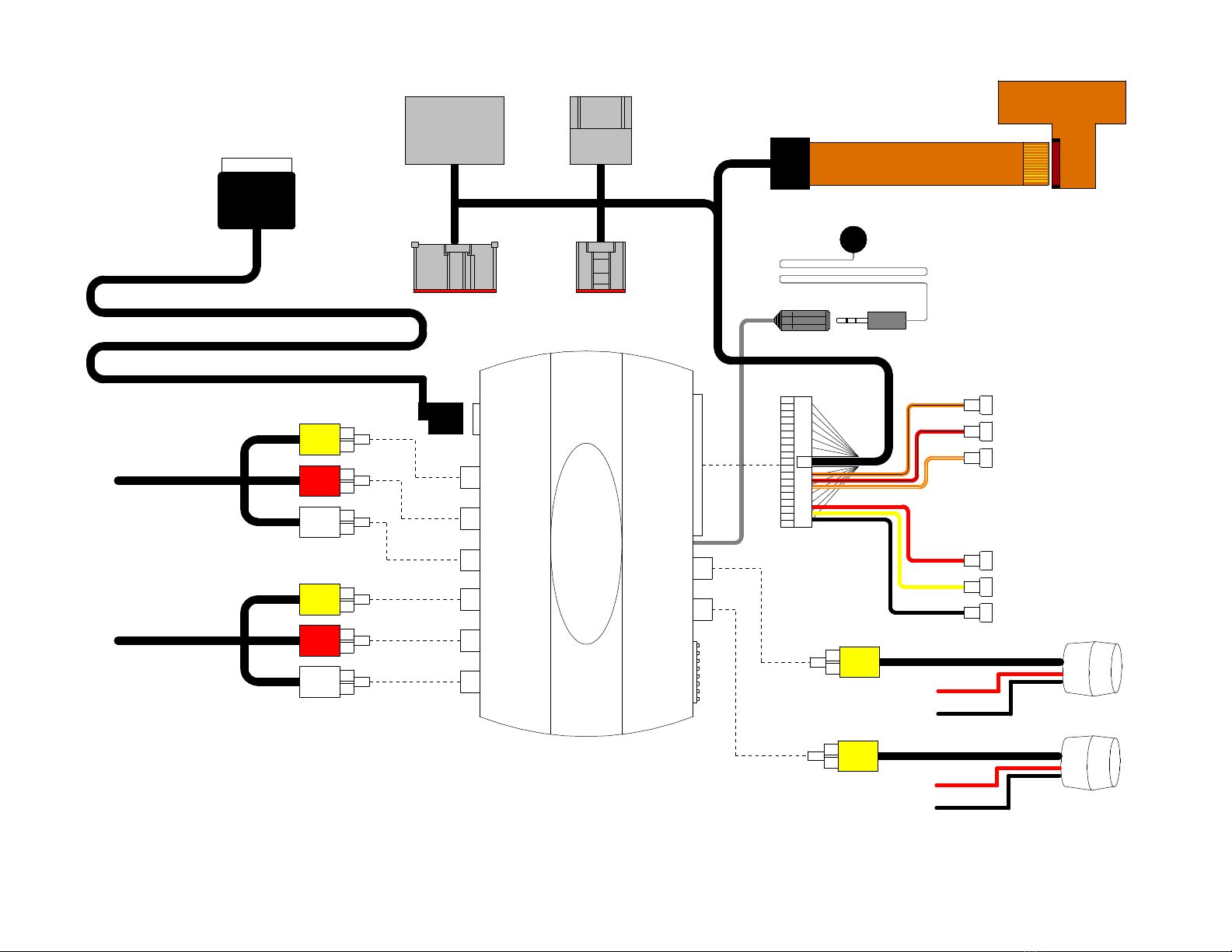
The UFRD-360-2 Lockpick is designed to allow video and audio input for cameras and multimedia equipment
directly to your factory screen. The UFRD-360-2 Lockpick incorporates many important features including :
Creates DVD mode in vehicles that do not have a factory rear entertainment system.
Direct RCA connections for easy STEREO AUDIO AND VIDEO INPUT.
Direct RCA connection for a rear view camera that can be activated automatically while in Reverse or
manually at any time
Direct RCA connection for a second camera input such as a front or interior baby camera.
Special cables and connectors for plug-in installations that are completely reversible
Audio and Video input from your iPod, iPhone, or iPad with full control, plus it charges your connected
device.
At this time, Coastal Electronic Technologies, Inc. would like to recommend that you have this installation
completed by a certified mechanic or someone familiar with automotive electronics. This installation, while not
time consuming, does require careful attention to detail and precise following of installation instructions.
Coastal Electronic Technologies, Inc. accepts no responsibility due to the improper installation or use of this
product. Installation and / or use of this product implies and signifies user acceptance of this term of use. Please
adhere to all driving laws in your state.
INSTALLATION
OVERVIEW
1. Watch the included DVD to become familiar with the entire installation process.
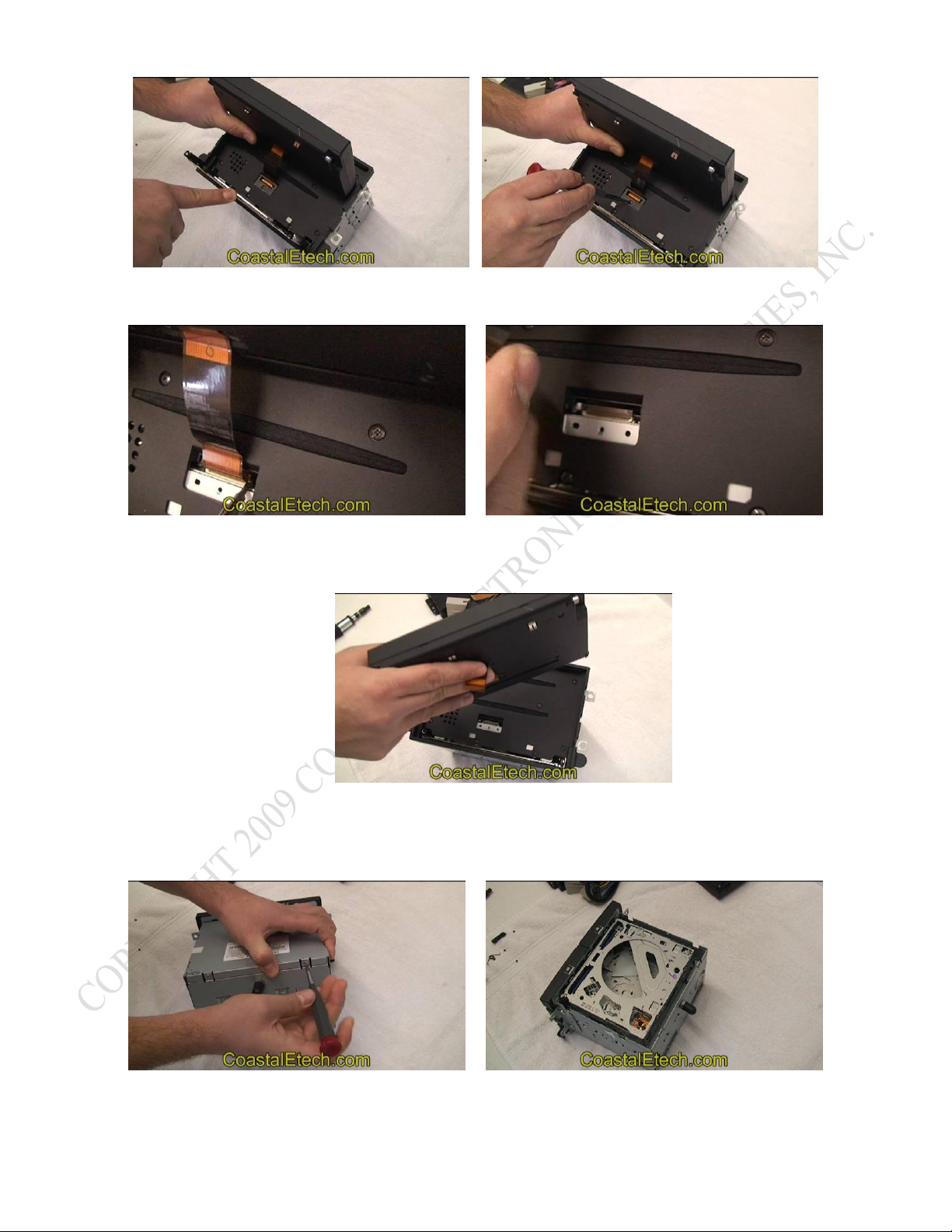
2. Remove the radio and prepare a work area for installation of the ribbon cable assembly.
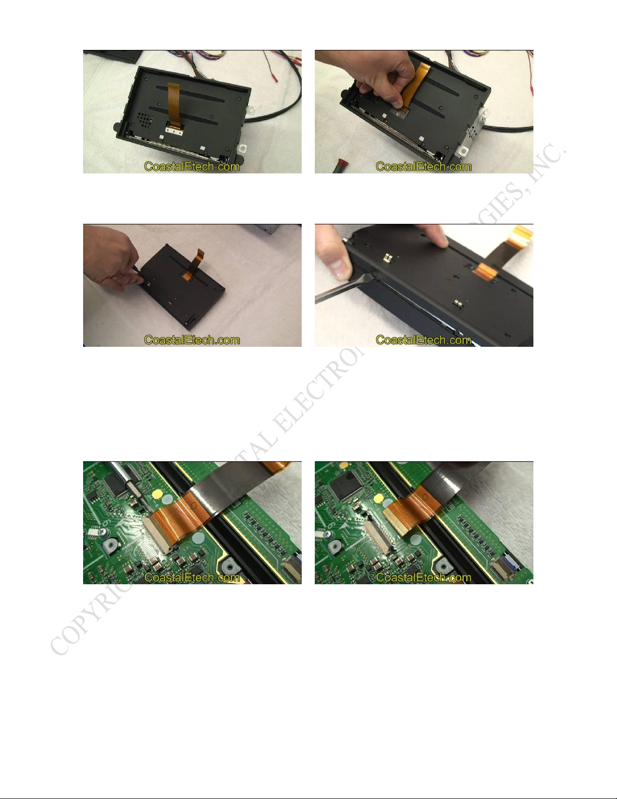
3. Lift up screen assembly from radio and disconnect factory ribbon cable.
4. Remove hinge screws to release screen from radio.
5. Remove faceplate and lid of radio.
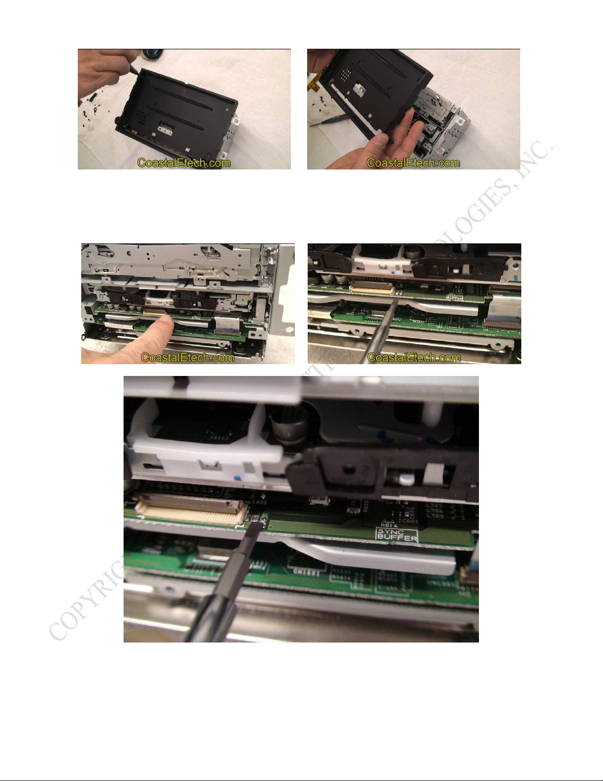
6. Insert UFRD-360-2 Lockpick flat ribbon cable 1 through rear of radio and connect it to Lockpick flat
ribbon cable 2.
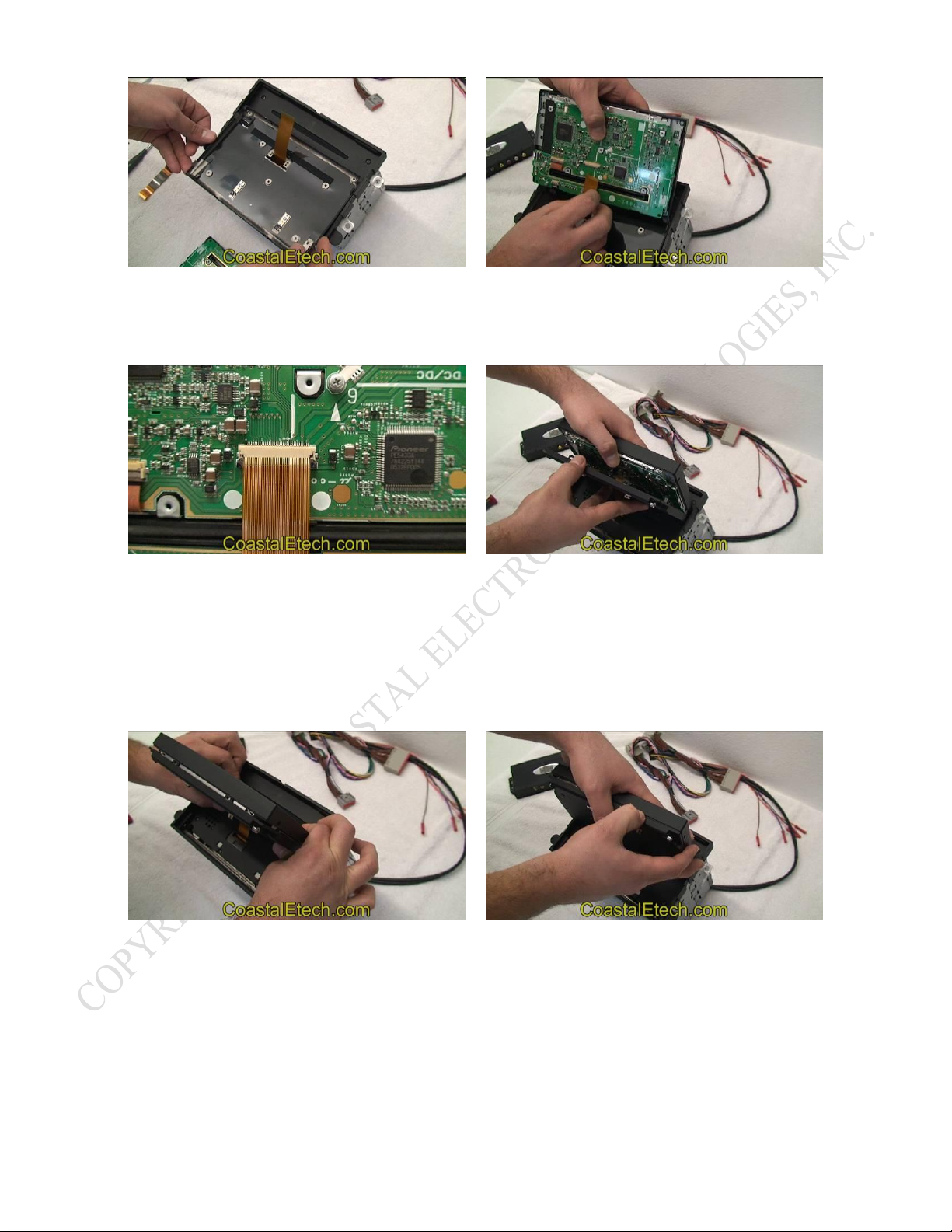
7. DISCHARGE RADIO BY GROUNDING CIRCUIT POINTS DETAILED IN THESE
INSTRUCTIONS AND DEMONSTRATED IN DVD.
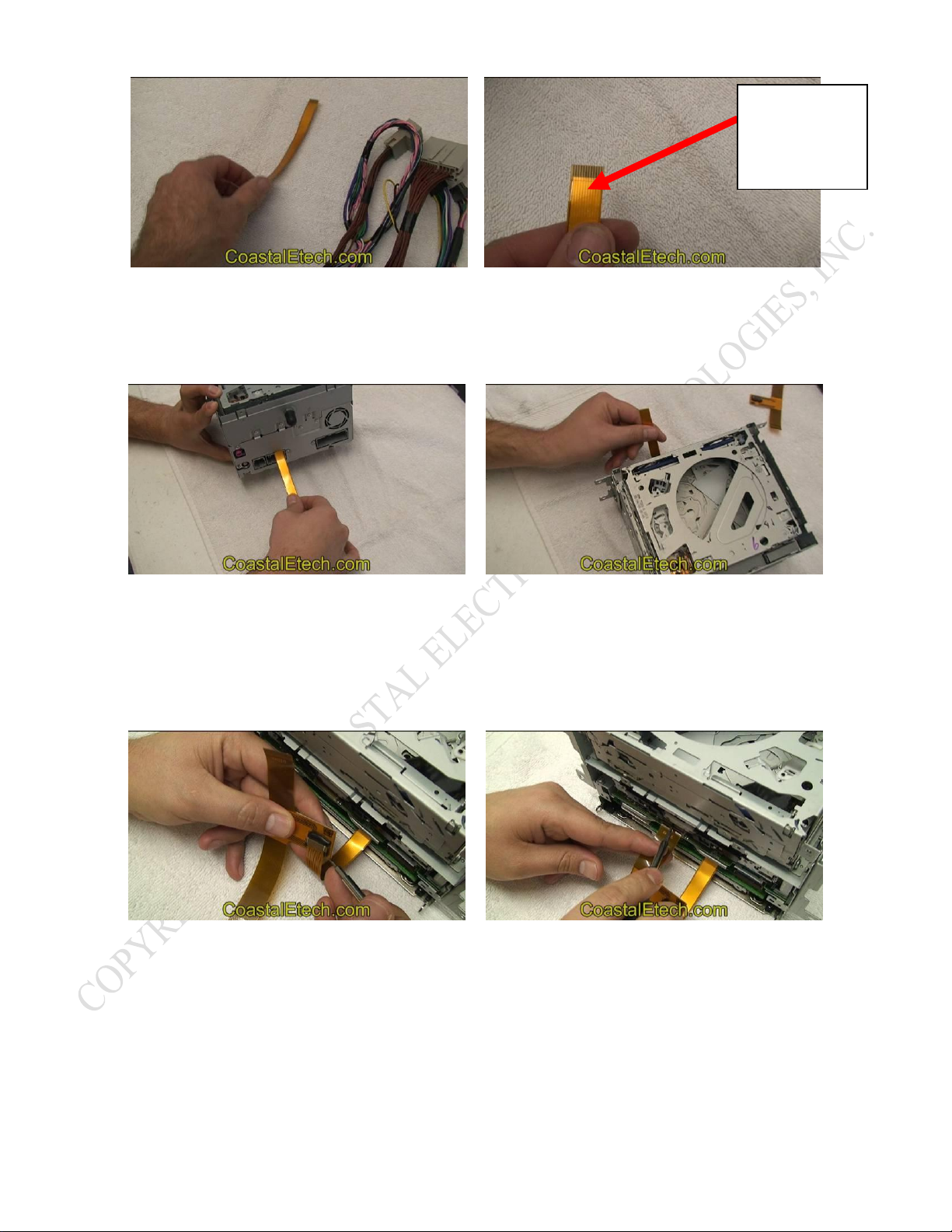
8. Plug in ribbon cable 2 to radio ribbon connector and place other end through faceplate.
9. Remove screen rear cover and disconnect final end factory ribbon cable.
10. Position Lockpick ribbon cable through rear screen cover and plug into screen connector.
11. Reassemble screen cover and install hinge screw..
12. Press screen back down into radio.
13. Plug in main wired Lockpick harness to rear of radio.
14. Set dip switch setting options and then connect wired harness to factory connectors in vehicle.
15. Connect iPod docking cable plus any additional accessories
16. Plug in remote control sensor.
TOOLS NEEDED (for ribbon cable insertion)
1. Small Phillips screwdriver
2. Small standard screwdriver

This written installation will detail the insertion of the flat internal radio harnesses to the Ford/Lincoln
navigation radio. Included in your kit is a video demonstrating the complete installation.
1. Begin by removing the Ford/Lincoln radio and positioning it on a suitable work area. Pivot the screen
outward by grabbing and gently pulling the bottom tray until the screen is fully extended .
2. Next, turn the radio over and remove the screws and the ribbon cable cover on the back of the screen.
3. Remove the hinge screws for the screen on each side along with the spring on the right side.
4. Press tray back into radio, then remove screws and ribbon cable cover on the radio faceplate..

5. Disconnect ribbon cable in radio by lifting up the locking tab on the side of the radio connector.
6. Turn the screen to release it from its faceplate guide tracks and set aside the screen assembly.
7. Turn the radio around and remove the 2 screws attaching the lid. Lift up and remove the lid of the radio
by prying up and releasing the clips on the edge.
8. Now remove the screws attaching the faceplate and then remove the faceplate temporarily.

9. **IMPORTANT ** Locate the grounding points pictured below. With a small screwdriver or other
conductive tool, touch the two circuit board traces together for 7 seconds. The radio must be discharged
to turn it fully off before installing and replacing the ribbon cable. Failure to discharge the circuit board
can result in permanent radio damage.
10. After discharging the circuit board, locate the Lockpick harness with attached ribbon cable. Position the
cable with the shiny contacts facing down and the insulated side visible in the top.

11. Insert the ribbon cable into the back of the radio in the space just above the factory connector shown in
the photos below. Slide the cable all the way through the radio and out the front.
12. Now locate the second small Lockpick ribbon cable and position it in the front of the radio so it can be
connected to the first cable. Unlock the ribbon cable 2 connector and insert cable 1 into cable 2. Next,
insert the ribbon cable assembly into the open radio connector (same one you removed the screen cable
from earlier) and lock it into place. The proper ribbon cable end is labeled RADIO to help you orient
the cable properly. Insure that the ribbon cable is fully inserted and perfectly straight.
13. Fold the cable and press the assembly fully into the radio with just the single open end of the ribbon
cable labeled screen left extending out the front. Gently pull any extra ribbon cable out the back of the
radio to complete this step.
CORRECT
Contact side
DOWN

14. The ribbon cable installation will look like the picture on the left when complete. Peal the adhesive strip
backing off of ribbon cable 1 and attach the cable to the back of the radio as shown on the right.
15. Place the radio lid back into position and reinstall the screws.
16. Reinstall faceplate and screws as well as the ribbon cable cover.

17. Remove the screws from the back and sides of the screen. Then separate and remove the cover from the
back of the screen.
18. Next we will remove the factory ribbon cable from the screen. Lift the locking tab on the connector and
unplug the cable. This cable will be replaced with the Lockpick ribbon cable already installed in the
radio. Save this cable and your system can be returned to its prior state anytime you desire.
19. Position the screen rear cover removed earlier, over the radio Lockpick ribbon cable as shown below so
that the cable extends through the slot in the cover. Then lift the screen up to the radio and insert the
ribbon cable into the screen connector.

20. After insuring that the ribbon cable is fully inserted and perfectly straight, lock the cable in by pressing
down on the connector locking tab. Then begin to press the two parts of the screen back together.
21. Press the front edges of the screen together first as shown below. Then using your thumb, press in on the
two rear screen clips while squeezing the halves of the shell together.
22. Reinstall the ribbon cable cover on the back of the screen and then pull the tray back out of the radio to
prepare for reattaching the screen hinges.

23. Install the hinge screw in the left side first. Then place the hinge spring into the hole in the bottom of the
screen and bend it around into position on the hinge with the long side captured under the metal tray.
24. Install the right hinge screw and then pivot and press the screen assembly back into the radio face.
25. Plug the other connectors of your Lockpick harness into the back of your radio to complete the radio
installation.

26. Before plugging the Lockpick module into the harness, set the dip switches on your module to the all UP
position. After the module is installed and tested, scroll to the on-screen menu for SETUP and select
FORD for the application and answer whether or not your vehicle already has factory rear seat
entertainment. This will set up the Lockpick for proper picture format and communications.
27. The Lockpick module has several RCA connectors on it for Camera and Multimedia inputs. Plug in
your aftermarket rear, front or both cameras into the Lockpick at this time. Also, additional Video and
stereo Audio Jacks are present for external DVD players, etc. The multimedia A/V input can be used for
sound input only, for a third camera or for full audio + video input from this source.
28. Plug in the iPod docking cable to the Lockpick module. The docking cable will provide all music, video
and communications from the iPod/iPhone/iPad to the Lockpick module. The cable will also provide
charging for your device while your vehicle is turned on.
ADDITIONAL HARNESS CONNECTIONS
29. The plug and play radio connectors connect the radio power to the Lockpick module automatically and
no extra connections are necessary for power or ground. When the vehicle is turned off and the door is
opened, the radio turns itself off and so does the Lockpick module. There is no power drawn by the
Lockpick module when the car is off so it will not drain your battery.
30. The Lockpick harness contains an ORANGE w/WHITE strip wire labeled 12V REVESE INPUT that
can allow the interface to monitor when the vehicle is in reverse and automatically switch to a rear
camera view. If you are installing a rear camera, connect this wire to a reverse taillight 12V source in
your vehicle (or to the reverse taillight) to signal the interface when the car is in reverse.
31. If you are installing a rear view camera, a 12V power connection is already included in your
LOCKPICK harness to power your camera automatically while in reverse and also whenever you have
selected it with the remote control. Connect the 12v power needs of your rear view camera to the
Orange w/Black stripe wire of your Lockpick harness labeled 12V OUT TO CAMERA. Do not power
your camera from the vehicle’s reverse taillight. Doing so will prevent the Lockpick from being able to
activate and view the camera when the vehicle is not in reverse.
32. Your Lockpick harness is also equipped with two 12v power outputs that you may use to power low
current devices (1.5 AMPS constant max) such radar detectors, second cameras, small DVD players etc.,
or to control a relay for even larger current items. The 12v ACC power out on the Lockpick harness
(solid RED) will turn off when the car is turned off to prevent battery drain from attached devices. The
Solid YELLOW constant power output will stay powered after the car shuts off. Note: Do not connect
the Lockpick power outputs to the wiring of your car. This is an output from the Lockpick for your
accessory needs and not an input.
33. There is an additional power output on the LOCKPICK harness labeled 12V FRONT CAMERA
OUTPUT (RED w/BLACK stripe) which you can use to power any second camera you may wish to
install.
34. A BLACK ground wire is included in your LOCKPICK harness which you may use as the ground
connection for your camera(s) or other accessories.

35. Plug in the REMOTE detector cable with remote “eye” into the small phono plug on your Lockpick
module and place the “eye” within view anywhere in the vehicle.
OPERATION OF THE UFRD-360-2 LOCKPICK
All functions of the Lockpick can be controlled by a simple, yet powerful in function, remote control. Insert the
included battery in your remote control and point it at the remote eye installed earlier.
NOTE: Many features The UFRD -360-2 Lockpick can also be controlled using the radio buttons, without using
the supplied remote. These special features are described later in the manual.
Select buttons and operations detailed below:
1. OFF –Press the “OFF” button to return the picture and sound to standard radio operation.
2. IPOD –RADIO MUST BE IN THE DVD or AUX MODE (See SETTINGS below) - Press to switch off
of any current view on your radio to the iPod search function for your attached iPod, iPhone, iPad. See
special operations while in iPod mode below.
Not used for
Ford
applications
8.
6.
9.

3. A/V INPUT –RADIO MUST BE IN THE DVD or AUX MODE (See SETTINGS below)- Press to
switch off of any current view on your radio to the picture source attached to Lockpick module Audio
and Video input.
4. CAMS –Press to switch off any current view and instead view the video from your attached camera(s).
5. AUX AUDIO ONLY –RADIO MUST BE IN THE DVD or AUX MODE, press the AUX AUDIO
ONLY button to listen to the audio source connected to the Lockpick. Also, you may toggle the video off
or back on again by pressing the aux audio button repeatedly while in iPod or A/V input modes.
6. BACK, SELECT and ARROW keys are used for navigating and selecting ON SCREEN MENUS or
IPod search functions.
7. || Press to PAUSE and PLAY selected iPod music or video.
8. HEADREST OUTPUT SELECT –Included on your Lockpick module are A/V outputs for connection
of an external screen or headrest display. Select the source you would like to hear and view using the
OFF, IPOD, AV INPUT, or AUX AUDIO ONLY buttons.
9. SETTINGS allow the user to select the proper vehicle format and other various settings available for
initialization. IT IS IMPORTANT TO SELECT SETTINGS AND THEN IDENTIFY YOUR VEHICLE
TYPE FROM THE LIST (FORD). ALSO, IF YOUR VEHICLE DOES NOT HAVE A FACTORY
REAR ENTERTAINMENT SYSTEM ALREADY PRESENT, THE LOCKPICK NEEDS TO CREATE
THIS MODE FOR OPERATION OF AUDIO IN IPOD OR AUX A/V MODES. SELECT THE FORD
RES ENABLE OPTION IN THE SETTINGS MENU WHEN FIRST INITIALIZING THIS PRODUCT
FOR USE IF YOUR VEHICLE DOES NOT ALREADY HAVE A DVD MODE.
If your vehicle already has the factory rear entertainment system present and the radio has a DVD
mode, then select the FORD W/O RES MODE. This will not add the RES mode or conflict with the
system already present in your vehicle.
10. The remainder of the buttons allow the user to customize the picture for day or night use or to increase
or lower brightness, contrast, color and tint.
DVD
mode
enabled

Special operations when iPod function is selected
The FORD 360-2 Lockpick can provide full search and play capabilities including music and video for
all capable Apple devices. Begin by placing your radio in the DVD mode. Then connect your iPod, iPhone or
iPad and select the IPOD mode on your Lockpick remote.
The screen view will change from your standard radio view to the Lockpick IPOD screen. From here
you can select 1 of 3 options.
SIMPLE MODE –If simple mode is selected, the control of the device remains with the
iPod/Iphone/iPad. You may browse and select any function or APP on your Apple device using its touch
pad, etc.. If you select a song on your iPod, the music will play through your factory sound system. If
you select a video, the picture will play on your screen along with the audio. You may also select
YouTube videos or APPS like Netflix and stream the video and audio to your screen. Also, other APPS
like Pandora radio or iHeart radio can stream music through to your radio system for unlimited
internet radio.
MUSIC –When the MUSIC mode is selected, the Lockpick will connect with your device and determine
if it is capable of a special function called IPOD OUT graphics. IPOD OUT is available on iPhones and
iTouch iPods running software greater than version 4.0. Also iPads 1 and 2 running current software,
and 6th Gen iPod nanos are iPOD OUT capable.
The IPOD OUT graphics will display on the factory screen and allow full music searches using your
Lockpick remote search keys. This includes Album, Artist, Playlists and all other standard iPod search
methods. Also, if you are searching a long list, you may hold down the Up or Down keys on your remote and
the search will change to an alphabetical search allowing quick lookups for large libraries. Select your
choice using the SELECT button on your remote control. Press BACK to return to a previous menu.
Your screen will display all available music graphics including
album covers and song information during your searches and after you make your selection.

If your iPod does not support IPOD OUT graphics,
the Lockpick will create its own search graphics.
For example, you can scroll down to Artists, and Select your choice from the displayed names using the
Lockpick remote. Then view all the songs from this artist and make your selection.
After picking a song, the Lockpick will show all information about
the song playing including a time graph.
VIDEO –When VIDEO is selected from the main Lockpick IPOD menu, the Lockpick will
determine all videos present in your iPod / iPhone / iPad and allow their selection.
The LOCKPICK will allow all videos to play from your iPod / iPhone / iPad to your radio screen.
Video searches include all movies presently stored on your device,
as well as music videos, TV shows and video podcasts.
Enjoy and Thank You for your trust in Coastal Electronics, Inc.
Table of contents
Popular Recording Equipment manuals by other brands

Live Show Control
Live Show Control MediaStar Pro Hardware user's guide

Iso-Max
Iso-Max CI-RJ2R-T user guide

Lighted Piston
Lighted Piston LPC-1 installation instructions

Universal Devices
Universal Devices ISY-994i Series user guide

Distech Controls
Distech Controls UNIWAVE Series installation guide

ACI-AppliCAD
ACI-AppliCAD TIF-102 Installation and use