Coastal WEATHERPAK TRx User manual

820 First Avenue South Seattle, WA 98134 USA www.CoastalEnvironmental.com
(206)682-6048 (800)488-8291 Fax: (206)682-5658 ISO 9001:2008 Certified
WEATHERPAKTRx
(formerly WEATHERPAK400)
User Manual
P/N 0302109011 Version 7.2 Rev. B
October 28, 2002
With Minor Revisions November 28, 2012
COASTAL ENVIRONMENTAL SYSTEMS
820 First Avenue South •Seattle, WA 98134
(206) 682-6048 (800) 488-8291 Fax: (206) 682-5658
www.CoastalEnvironmental.com

WEATHERPAK®TRx
USER’S MANUAL
P/N: 0302-109-011 Rev. BPage i
TABLE OF CONTENTS
LIST OF FIGURES 1
IMPORTANT NOTES 2
1.0 INTRODUCTION 3
2.0 INSTALLATION 4
2.1 Siting Considerations 4
2.2 Tower Mount 5
2.3 Van Mount 7
2.4 Receiver Box Connections 9
2.5 Connection to a Computer 10
3.0 OPERATION 11
3.1 Receiver Box Display Interpretation 11
3.2 Using the Computer with Plume Modeling Software 12
3.3 Data Line Interpretation 14
4.0 MAINTENANCE 15
4.1 Periodic Maintenance Schedule 15
4.2 Troubleshooting 15
4.3 Replacing Tower Batteries and Fuse 17
EQUIVALENT WIND CHILL TEMPERATURES 18
HEAT STRESS INDEX 19

WEATHERPAK®TRx
USER’S MANUAL
P/N: 0302-109-011 Rev. B 1
LIST OF FIGURES
1. Placement of the WEATHERPAKon top of vehicles 4
2. The WEATHERPAKTRx with Tower 5
3. Tower Mount Setup 6
4. The WEATHERPAKTRx VM (Van Mount) 7
5. Van Mount Quick Release 8
6. Receiver Box Rear Panel Connections 9
7. Computer with Receiver 10
8. Receiver Front Panel 11
9. ALOHA screen capture 13
10. ALOHA map 13
11. Replacing the batteries 17
12. Replacing the batteries (2) 17

WEATHERPAK®TRx
USER’S MANUAL
P/N: 0302-109-011 Rev. B 2
IMPORTANT NOTES
DO CALL/FAX US IF YOU HAVE QUESTIONS OR PROBLEMS
Call Coastal Environmental Systems if any troubles arise or if you have any questions pertaining
to the equipment. Our telephone number is 206-682-6048 and the FAX number is 206-682-
5658. Refer to the model number (WEATHERPAKTRx) and the serial number of the
WEATHERPAK.
DO WASH OFF CHEMICALS OR DEBRIS WHILE THE WEATHERPAKIS
ASSEMBLED to prevent getting water in the connectors. The WEATHERPAKis water-
resistant when assembled.
DO FOLLOW THE MAINTENANCE SCHEDULE. (See the periodic maintenance schedule
in Section 4.1)
INCORRECT WIND SPEED WILL RESULT IF THE PROPELLER NUT IS NOT
TIGHT.
DO NOT OPEN THE WEATHERPAK. It is purged with desiccant bags to seal out all the
moisture. Opening it may allow moisture to foul the electronics and will invalidate the warranty.
DO NOT PICK UP THE WEATHERPAKBY THE WIND VANE. This is a durable but
sensitive wind sensor and it can be broken if it is used to lift the entire unit.
DO NOT REMOVE THE ANTENNA FROM THE WEATHERPAK. If the
WEATHERPAKis activated without the antenna, the radio can be damaged.
REPLACING TOWER BATTERIES. WARNING: DO NOT LEAVE BATTERIES IN
TOWER WHEN STORING OR SHIPPING TOWER ASSEMBLY. BATTERIES MAY
LEAK CAUSING DAMAGE TO UPPER TOWER SECTION.

WEATHERPAK®TRx
USER’S MANUAL
P/N: 0302-109-011 Rev. B 3
1.0 INTRODUCTION
A WEATHERPAKTRx measures the air temperature and the speed, direction and stability
class of the wind. As an option, it can measure barometric pressure and relative humidity.
Information is sampled every 2 seconds and then computed into a 5-minute running average.
The data is then transmitted to you every 30 seconds for an updated line of data.
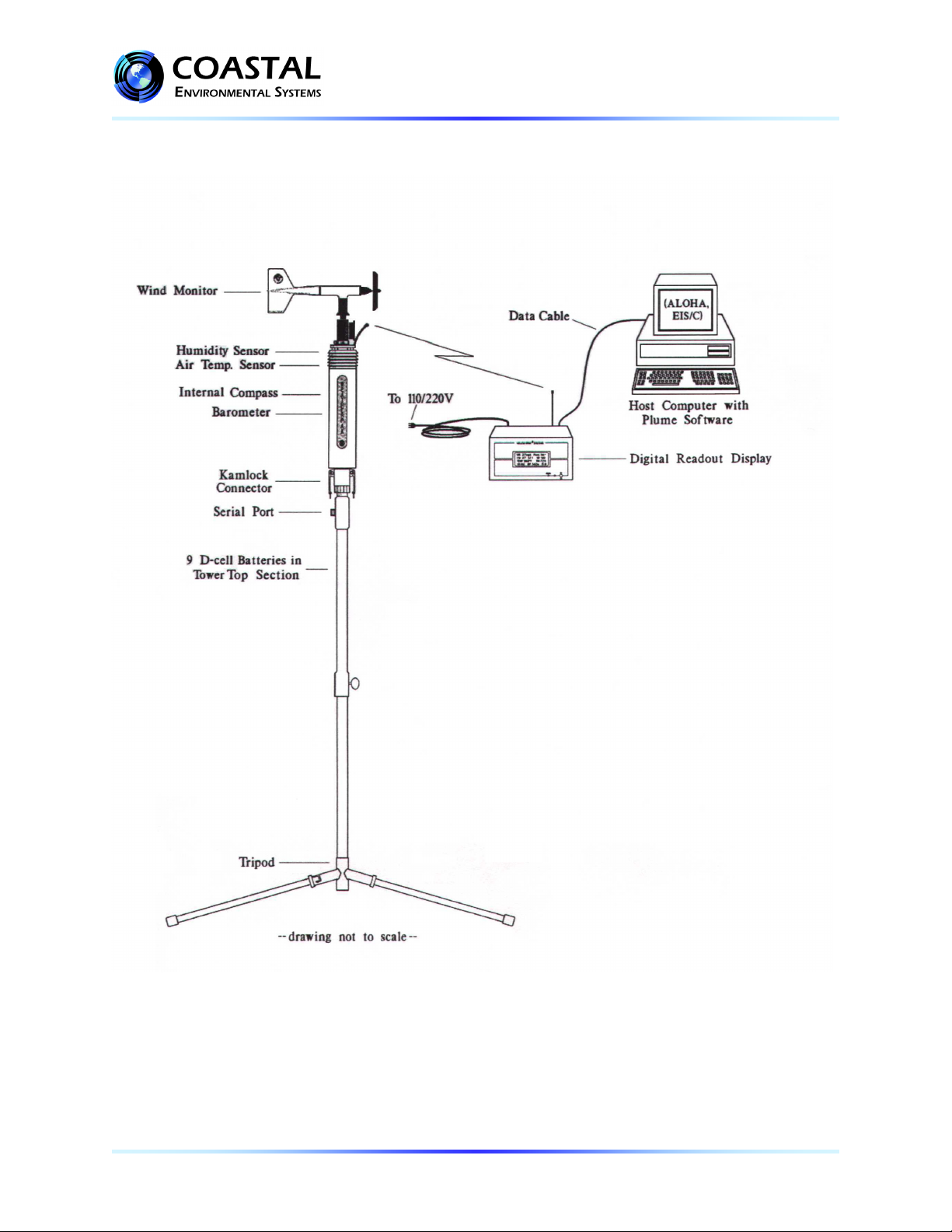
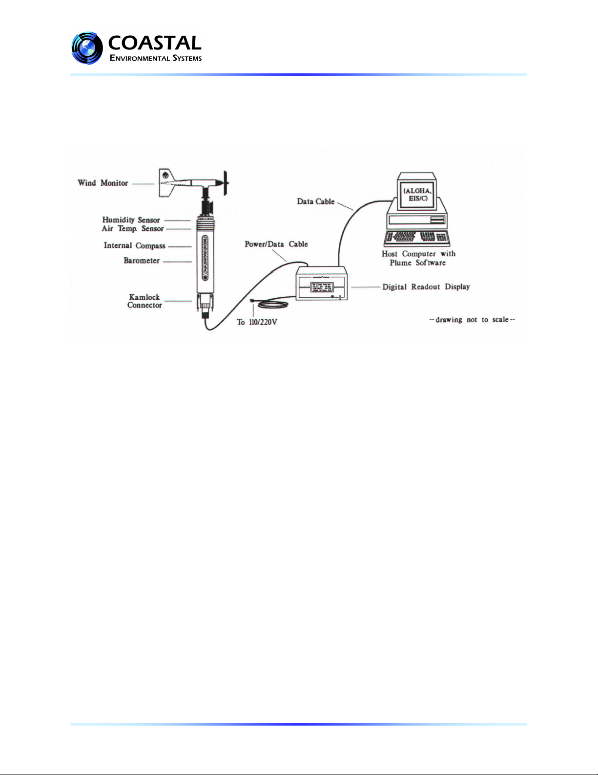
A WEATHERPAKTRx is suitable for extremely portable use when mounted on a van or a
portable tower. It can also be mounted at a fixed site, such as an industrial plant.
The WEATHERPAKwas designed with the following unique features for use in hazardous
materials response:
•A built-in electronic compass allows the WEATHERPAKto be set up in any orientation – it
will automatically determine true North and give you true wind direction. 1
•Setup time is under two minutes.
•When the unit is assembled, there are no electrical connections that can spark.
•The housing is constructed of 6061-T6 aluminum that is non-corrosive and will not spark if
dropped or struck.
•The housing is sealed and dried with desiccant to protect the electronics against moisture.
This means that the WEATHERPAKcan easily withstand decontamination procedures.
•A beeper in the tower sounds when battery replacement is required because of low voltage in
the battery pack. 2
•All of the electronics are grounded at a single point to protect the WEATHERPAKagainst
unexpected large voltages and radio interference.
This manual will familiarize you with the installation, operation and maintenance of a
WEATHERPAKTRx. Please read all of the instructions before attempting to operate or
troubleshoot the WEATHERPAK.
__________________________
1The variation of True North from magnetic North is entered into your WEATHERPAKfor your location. It is
easily changed, but should not be done so without first consulting Coastal Environmental Systems. (requires test
cable)
2 The WEATHERPAKmust be installed for the beeper to function.

WEATHERPAK®TRx
USER’S MANUAL
P/N: 0302-109-011 Rev. B 4
2.0 INSTALLATION
2.1 Siting Considerations
a) Compass Measurements – Remember that the WEATHERPAKcontains a compass for
automatic North alignment. Like any compass, it can make an error if located too close
(laterally) to large amounts of steel or other magnetic material. (In other words, on top of a van
is OK, but next to it is not an ideal location.) Try to place the WEATHERPAKat least 30
meters from large vans, busses, cranes, etc.
b) Wind Measurements – Select as exposed a site as is possible. The wind pattern around a
building or other obstacle is disturbed for a considerable distance. If the WEATHERPAKis
placed immediately North of your vehicle and the wind is coming from the South, an erroneous
wind direction and speed reading will result.
c) Radio Transmissions – Locate the WEATHERPAKas close as safety permits within 2
miles of the receiving unit. Do not attempt to transmit through structures containing steel, or
through hills. 3
Figure 1. Placement on top of vehicles is okay
__________________________
3Ideal conditions. Reception range will vary depending on radio signal path.

WEATHERPAK®TRx
USER’S MANUAL
P/N: 0302-109-011 Rev. B 5
2.2 Tower Mount
Figure 2. The WEATHERPAKTRx with tower

WEATHERPAK®TRx
USER’S MANUAL
P/N: 0302-109-011 Rev. B 6
TOWER MOUNT SETUP
1) Lock the legs on to the bottom section
of the tower forming the tower tripod
base.
2) Remove the wind vane from the case.
Place the propeller on the front shaft, screw
the nut into place on the propeller shaft to
secure the propeller.
3) Plug the wind vane into the top of the
WEATHERPAK. There is an alignment pin
and slot inside the connector to assure a
proper and aligned fit.
Be certain that the wind vane is plugged all
the way in.
DO NOT rotate the wind vane when
installing or removing.
4) Align the slot on the WEATHERPAKwith the
guide pin on the quick release and push straight in.
(DO NOT “screw” the WEATHERPAKonto the
quick release.) This is a good sealed fit and may
require an extra push - then push the arms of the
clamp down to assure a tight fit.
DO NOT rotate the WEATHERPAKor tower
when installing or removing.
5) Place the entire unit – tower top and
WEATHERPAK– onto the tripod and securely
tighten the tower locking knob.
6) The WEATHERPAKis now running and is
sampling. When the WEATHERPAKis
removed from the Quick Release, it will stop
sampling and shut itself off.

WEATHERPAK®TRx
USER’S MANUAL
P/N: 0302-109-011 Rev. B 7
2.3 Van Mount
Figure 4. The WEATHERPAKTRx VM (Van Mount)

WEATHERPAK®TRx
USER’S MANUAL
P/N: 0302-109-011 Rev. B 8
VAN MOUNT SETUP
1) Remove the wind vane from the case. Place the propeller on the front shaft screw the nut
into place on the propeller shaft to secure the propeller.
2) Plug the wind vane into the top of the WEATHERPAK. There is an alignment pin and slot
inside the connector to assure a proper and aligned fit. Be certain that the wind vane is
plugged all the way in. DO NOT rotate the wind vane when installing or removing.
3) Align the slot on the WEATHERPAKwith the guide pin on the quick release and push
straight in. (DO NOT “screw” the WEATHERPAKonto the quick release.) This is a good
sealed fit and may require an extra push - then push the arms of the clamp down to assure
a tight fit. DO NOT rotate the WEATHERPAKor tower when installing or removing.
Also, a series of about 5 beeps, should be heard. (portable tower only)
4) The WEATHERPAKis now running and is sampling. When the WEATHERPAKis
removed from the Quick Release, it will stop sampling and shut itself off.
Figure 5. Van Mount Quick Release
The Van Mount Quick Release is permanently mounted on a vehicle. Because of the
variability of vehicles, the lower part of this bracket is assumed to be customer furnished.
Coastal supplies the above with 1-½” female SPT.

WEATHERPAK®TRx
USER’S MANUAL
P/N: 0302-109-011 Rev. B 9
2.4 Receiver box connections
Figure 6. Receiver box rear panel connections.
INTERNAL SWITCHES
The following internal switches change the functions of the RX Box Display only. 4
NOTE: DO NOT open the receiver/display box without permission from Coastal
Environmental Systems Customer Service, as doing so may void your warranty.
Always disconnect the A/C power cord before opening the box. The receiver box contains
many static sensitive parts which can be inadvertently damaged by improper handling.
DS1 Unused (remains off)
DS2 Standard = off / Metric = on
DS3 Degrees = off / Ordinal points = on
DS4 Unused (remains off)
DS5 English = off / French = on
__________________________
4The serial data will not be affected by switch settings.

WEATHERPAK®TRx
USER’S MANUAL
P/N: 0302-109-011 Rev. B 10
2.5 Connection to a computer
a) Plug the receiver box power cord into a power source. (110V unless otherwise marked)
b) Plug one end of the serial data cable into the computer free COM port.
c) Turn the receiver switch on.
d) The receiver power indicator light should now be on.
e) If the WEATHERPAKis set up and running, the carrier detect light on the receiver
should blink briefly every 30 seconds as data is received. If the light doesn’t blink, see
the section on troubleshooting.
Figure 7. Computer with receiver, Display option shown

WEATHERPAK®TRx
USER’S MANUAL
P/N: 0302-109-011 Rev. B 11
3.0 OPERATION
Once the WEATHERPAKis set up, it turns itself on, starts sampling and transmits data every
30 seconds.5You can view the data on the receiver box, or you can view and manipulate the data
on the computer using the ALOHA plume model software.
3.1 Receiver box display interpretation
EXAMPLE
Figure 8. Receiver front panel
The example is interpreted as follows: The five minute average wind (WS) is 2.7 miles per hour and is coming from
310 degrees. The instantaneous – one second wind speed (IW) is 2.7 miles per hour. The stability (ST) will range
from –1 to 100. The –1 is a default reading for the first 5 minutes. After that it will range from 1 to 100. The higher
the ST number, the more unstable the wind is with a corresponding wider area of concern. The air temperature
(TEMP) is 96.6 degrees Fahrenheit. The relative humidity (RH) is an option. The ID# is unique to your
WEATHERPAKand will allow you to identify your WEATHERPAKshould you respond to a spill where there
are several WEATHERPAKs. The barometric pressure (BP) in inches is also an option.
LOW POWER INDICATORS
There are low power warning indicators which will flash in the lower right corner of the display.
A flashing “R” indicates that the Receiver batteries are low.
R warning flash starts ≅11.5 VDC
Receiver lights go out ≅10.5 VDC
If the receiver lights go out, plug the receiver into a wall outlet, then reset the receiver by flipping
the power switch off then back on. This will recharge the batteries.
Batteries last = 4 hours
Recharge time = 1 hour
A flashing “T” indicates that the batteries in the tower are low and need replacing. (See Section
4.3 for replacement instructions.)
__________________________________
5The rate is factory set. Contact Coastal Environment Systems if there is a need to change the sampling or
transmission rates.

WEATHERPAK®TRx
USER’S MANUAL
P/N: 0302-109-011 Rev. B 12
3.2 Using the computer with plume modeling software
With the WEATHERPAKset-up and operational and the Receiver/Display box connected to your
computer, real-time data is available to run air dispersion plume modeling software.
IMPORTANT NOTE: Some versions of ALOHA (including 5.2.1) need to be upgraded in order to work with a
Station for Atmospheric Measurement (SAM); the WEATHERPAKis a SAM. The US EPA provides
CAMEO/ALOHA software downloads, support, and information at their website
http://www.epa.gov/osweroe1/content/cameo/index.htm. These addresses change periodically – we’d appreciate
knowing any changes you encounter.
The following is a brief outline on using the system to produce an ALOHA plume model on a PC
operating Windows 95. There is a general assumption that the user is familiar with ALOHA and that the
program is properly loaded on the user’s computer. Please consult the ALOHA user’s manual for
additional details and program limitations.
1. Open ALOHA by clicking on its desktop icon, or selecting it from the Programs menu
2. A series of dialogue boxes will appear including important notes on program limitations.
3. A Text Summary window will appear with information summarizing the event.
4. Confirm that your Site Data information is correct. If required, use the SiteData pull-down menu to
change it.
5. Using the pull-down menu SetUp/Chemical select the chemical (chlorine, for example).
6. Using the pull-down menu SetUp/Atmospheric/SAM Station a series of dialogue boxes will appear
requiring user observations or assumptions. Relative humidity data is not captured automatically and
can be hand-entered using data from the Receiver/Display box.
7. Using the pull-down menu SAMOptions select Processed Data. The WEATHERPAKdelivers data
in the proper format for ALOHA to use. A Processed SAM Data window will appear. If the
WEATHERPAKhas been collecting data for less than five minutes a warning message will be
displayed in both the Text Summary and Processed SAM Data windows.
8. Before allowing selection of the source of the leak (tank, pipe, direct etc.), ALOHA requires the
SAM station to record five minutes worth of data. Using the pull-down menu SetUp/Source select
the source of the leak (tank, for example); a series of dialogue boxes will appear requiring user
observations or assumptions.
9. Use the Display/Footprint pull-down menu to show the plume footprint. A footprint is required
before plotting the plume onto a street map. Refer to the ALOHA manual for interpretations and
explanations on selecting locations within the plume footprint.
10. Optional graphs: Use the Display pull-down menu to produce graphs for source strength release rate,
concentration, and dose.
11. Use the Display/Tile Windows to show multiple windows on the same screen; reposition and re-size
as needed. Display/Stack will organize and stack the windows for quick access.
12. To plot the plume onto a street map, use the Sharing pull-down menu. As weather conditions change
the plume size and position will change shortly after the WEATHERPAKprovides updated data.
Note: some software versions require that the ALOHA window overlay the map window in order for
the map-plume to update automatically.

WEATHERPAK®TRx
USER’S MANUAL
P/N: 0302-109-011 Rev. B 13
Figure 9. ALOHA screen capture
The WEATHERPAKtakes a sensor sample approximately every 1-2 seconds and calculates a five minute running
average and sends updated data approximately every thirty seconds. “INSTANTANEOUS” data is captured just
prior to the thirty-second update. By comparing the “5 MINUTE RUNNING AVERAGE” and
“INSTANTANEOUS” data, the user can get a good idea of changing conditions. The WEATHERPAKcalculates
“Sigma Theta”, or air mixing, and produces a Stability Class value used by the plume model. The battery voltage is
also transmitted. Note: If voltage is below 11.0 the batteries in the WEATHERPAKtower should be replaced.
Figure 10. ALOHA map

WEATHERPAK®TRx
USER’S MANUAL
P/N: 0302-109-011 Rev. B 14
If you pull down the “SAM Options” from the Main menu and select “Raw data”, something like
the following line of data will appear:
421, 0.9, 225, 1.0, 23.9, 1.0, 226, 23.9, 14.0, 1917, 999, 46, 2536
This is showing you exactly what the WEATHERPAKis sending. Notice that most of these
numbers are present in the “Processed Sam Data” on the previous page. The difference is that
there are no labels and there are some additional numbers. Also, this raw data is in metric units
(millibars, m/s, C), whereas the processed data is in standard English units (inches, m.p.h., F.)
The first number is the unique ID number (Serial #) of your WEATHERPAK. If you do not
have a WEATHERPAKdisplay screen, then this is how to identify your WEATHERPAKif
you respond to a spill where other WEATHERPAKs are present. If you have a
WEATHERPAKdisplay screen, the ID number appears on it.
Two “checksums” are performed to ensure that the message sent was correct. The computer adds
up the “ASCII value” of the data line (each letter and number and comma, etc., has a numerical
value universal to all computers) to make sure that the computer got the same number that the
WEATHERPAKtransmitted.
3.3 Data line interpretation
The data line fields are as follows:
ID, MW, MD, ST, AT, SI, DI, TI, BV, CKSUM1, BP, RH CKSUM2
ID – WEATHERPAKidentification number
MW – 5 minute averaged wind speed in meters per second
MD – 5 minute averaged wind direction in degrees
ST – Stability class in degrees
AT – 5 minute averaged air temperature in degrees Centigrade
SI – Instantaneous wind speed in meters per second
DI – Instantaneous wind direction in degrees
TI – Instantaneous air temperature in degrees Centigrade
BV – Battery voltage in volts
CKSUM1 – First checksum
BP – Barometric pressure in millibars
RH – Relative humidity in percent
CKSUM2 – Second checksum

WEATHERPAK®TRx
USER’S MANUAL
P/N: 0302-109-011 Rev. B 15
4.0 MAINTENANCE
4.1 Periodic maintenance schedule
Routine maintenance is required on the WEATHERPAKevery 12 months. This maintenance is
to ensure that the overall system and its sensors are working and performing to specifications.
The actual service varies, based on the sensors installed in your model of WEATHERPAK. For
example, a WEATHERPAKTRx should have the wind, compass, air temperature (and,
optionally, the barometric pressure and relative humidity) sensors tested to their stated
specifications. In addition, the entire WEATHERPAKshould be examined for any wear,
damage or other non-conforming variances.
4.2 Troubleshooting
Do not take the WEATHERPAKor the Receiver box apart; this will void the warranty.
If the procedures below do not solve the problem, call Coastal Environmental Systems.
4.2.1 The WEATHERPAK
Is the WEATHERPAKon?
Once the WEATHERPAKis set up, it turns itself on, and starts sampling and
transmits data every 30 seconds. If it does not:
Check that the WEATHERPAKis properly secured in the quick release – reseat firmly.
•Check the power connection to the WEATHERPAK, or
•Check the tower batteries and fuse.
4.2.2 The Receiver
Is the Receiver Box on?
The display light should be on and the display characters visible. If this does not
occur, do the following:
•Be sure the receiver unit is plugged in and turned on. Check the power light on the
front panel. It should be lit.
•If it is not lit, check for power at the outlet the RX Box is plugged into.
•Check the cable connections from the WEATHERPAKto the receiver, they might
be incorrectly wired. See section 2.4 figure 6.
Data light not flashing?
Every 30 seconds (approximately), the data light will flash signifying that the
WEATHERPAKis updating the display. If the light does not flash, then do the
following:
•Be sure the receiver unit is plugged in and turned on. Check the power light on the
front panel, it should be lit.
•Check to see if the WEATHERPAKis “line of sight” (less than 2 miles, and not
trying to transmit through hills, or steel walls, etc.)
•Be sure you are not trying to transmit through structures containing lots of steel.

WEATHERPAK®TRx
USER’S MANUAL
P/N: 0302-109-011 Rev. B 16
•Check to see if both antennas are connected (WEATHERPAKand receiver.)
•Unclamp, remove, wait 10 seconds, then replace the WEATHERPAKon the tower
(this resets it.)
•Check to see if the low battery beeper in the tower is beeping.
•Check that the batteries in the tower are properly aligned and are the correct voltage.
•Check the power connection to the WEATHERPAK.
•Check the cable connections from the WEATHERPAKto the receiver; they might
be incorrectly wired.
4.2.3 Wind speed off?
•Check that the propeller is turning.
•There is a minimum threshold of about 2.5 –3 MPH.
Propeller is turning, wind speed reads zero?
•Make sure that the wind monitor has been pushed down all the way on to the
WEATHERPAK. See page 6, step 3 - Tower Mount Setup.
Wind direction off?
For this job you need a partner. Have your partner go to the wind monitor and hold the
vane so the propeller points in a known direction. Does the display read correctly? If
not:
•Make sure that the wind monitor has been pushed down all the way on to the
WEATHERPAK. There is an alignment pin and slot inside the connector to
assure a proper and aligned fit; make sure that the pin is in the slot. See Step 3 and
Step 4 of Tower Mount Setup.
Other sensor readings off?
Contact Coastal Environmental Systems. The WEATHERPAKmay be broken or
require maintenance.
4.2.4 The Computer
There is data at the display but there is either no data or erroneous data at the
computer.
•Check all the connections from the receiver to the computer.
Error messages while running plume modeling.
These are not related to the use of the WEATHERPAK; these are coming from the
plume modeling software.
•Consult your CAMEO/ALOHA manual.
•Contact the National Safety Council for help with the plume modeling software.
•Contact Coastal Environmental Systems as a last resort. We are not authorized
CAMEO/ALOHA representatives; however, we may be able to help.

WEATHERPAK®TRx
USER’S MANUAL
P/N: 0302-109-011 Rev. B 17
4.3 Replacing tower batteries and fuse
WARNING: DO NOT LEAVE BATTERIES IN TOWER WHEN STORING OR
SHIPPING TOWER ASSEMBLY. BATTERIES MAY LEAK CAUSING DAMAGE TO
UPPER TOWER SECTION.
The WEATHERPAKhas nine alkaline D cell batteries which are located in the top section of
the tower, as shown in the figure below. The batteries can be replaced with standard alkaline
batteries. Make sure that the replacement batteries are of the same type.
There is an in-line fuse located in the tower junction box (see figure below.)
WEATHERPAK LOW BATTERY INDICATORS
1. A beeper will sound in the tower. The WEATHERPAKmust be installed.
Dead batteries will not activate the beeper.
2. A “T” will flash on the Receiver front panel (see Sec. 3.1.)
3. The battery voltage reads below 11.0 on the “Processed Sam Data: screen (see Sec.
3.2.)
Figure 10. Replacing the batteries
Figure 11. Replacing the batteries (2)
You will need a large screwdriver to replace the batteries. The battery “plug” is slotted. With
the screwdriver, PUSH (the plug is held in place by a spring) and rotate the plug clockwise.
The plug will come out followed by a spring and the batteries. Slide the new batteries in
(positive end first) and replace the spring and plug.

WEATHERPAK®TRx
USER’S MANUAL
P/N: 0302-109-011 Rev. B 18
To check the new voltage, set up the WEATHERPAKand get the ALOHA plume model
running. Then pull down the [MISC] menu to “Processed Sam data”. One of the items shown
is battery voltage (see figure 10 on page 14.) It should read about 13 to 15 volts. The tower low
voltage beeper will go off when the battery voltage reaches 11 volts.
Equivalent Wind Chill Temperatures of Cold Environments
Actual Thermometer Reading, °F
Wind
Speed,
mph
50
40
30
20
10
0
-10
-20
-30
-40
-50
-60
Equivalent Chill Temperature, °F
0
50
40
30
20
10
0
-10
-20
-30
-40
-50
-60
5
48
37
27
16
6
-5
-15
-26
-36
-47
-57
-68
10
40
28
16
3
-9
-21
-34
-46
-58
-71
-83
-95
15
36
22
9
-5
-18
-32
-45
-59
-72
-86
-99
-113
20
32
18
4
-11
-25
-39
-53
-68
-82
-96
-110
-125
25
30
15
0
-15
-30
-44
-59
-74
-89
-104
-119
-134
30
28
13
-3
-18
-33
-48
-64
-79
-94
-110
-125
-140
35
27
11
-4
-20
-36
-51
-67
-83
-98
-114
-129
-145
40
26
10
-6
-22
-38
-53
-69
-85
-101
-117
-133
-148
Little danger: In less than 5 h, with dry
skin. Maximum danger from false sense
of security.
Increasing danger:
Danger of freezing
exposed flesh within
one minute.
Great danger: Flesh may freeze within
30 seconds.
Table of contents
Other Coastal Weather Station manuals
Popular Weather Station manuals by other brands

La Crosse Technology
La Crosse Technology Tomorrow's Weather Today WS-7394U-IT instruction manual

Logia
Logia LOWSC713SWB user guide

Corintech
Corintech EL-WiFi-TH quick start guide

Oregon Scientific
Oregon Scientific WMS801 user manual

La Crosse Technology
La Crosse Technology C86234 Operation manual

Honeywell
Honeywell TE821W user manual