ZENO® Portable Weather Station Set-Up Guide
820 First Avenue South, Seattle, WA 98134 Tel: +1 (800) 488-8291 / +1 (206) 682-6048 Fax: +1 (206) 682-5658 www.CoastalEnvironmental.com
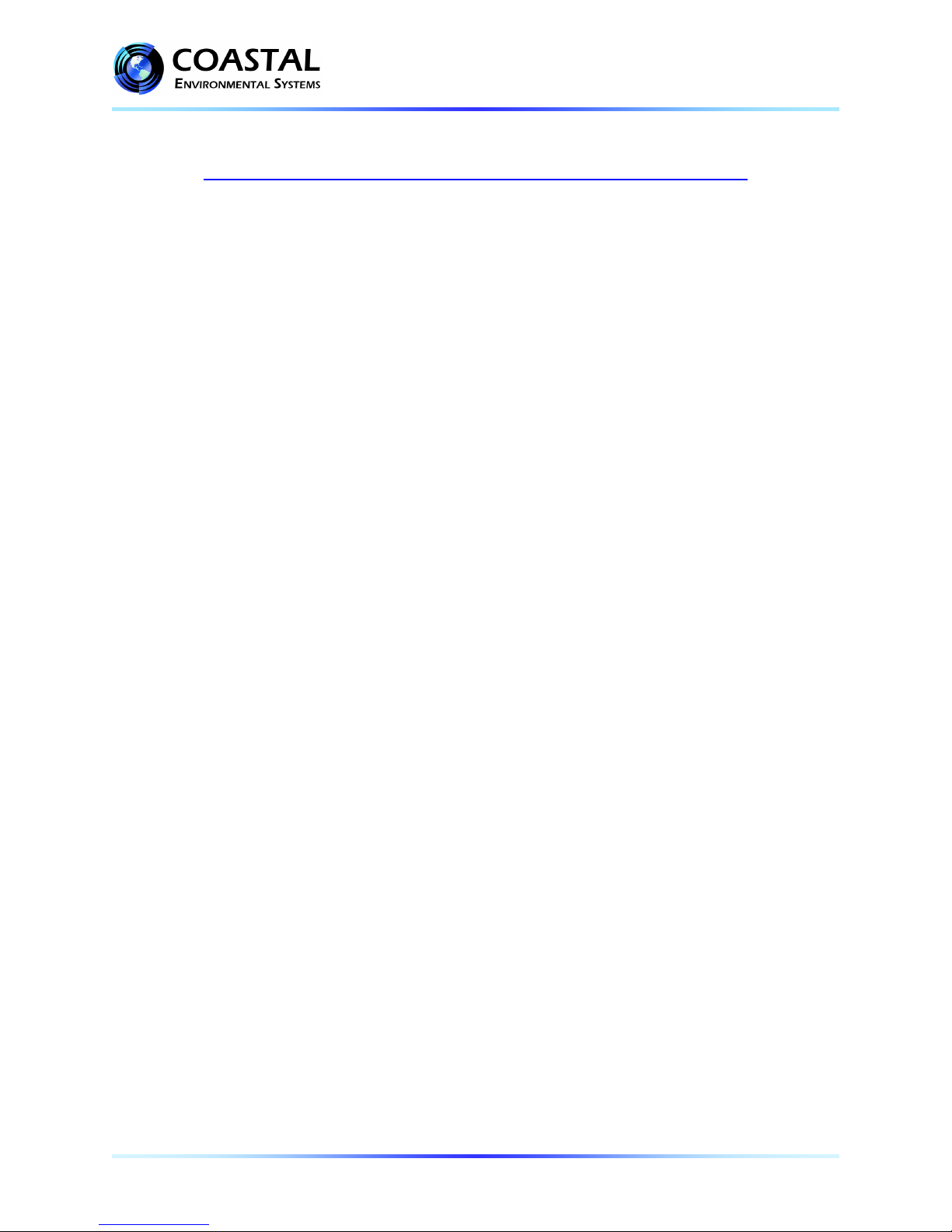
FACE SOUTH*
Place
1.5 METERS
above
ground
Wind Sensor
Solar
Radiation
Sensor
In Northern Hemisphere
Net Radiometer
Sensor
ZENO®
Enclosure
also holds the
Barometric
Pressure
Sensor
Soil Moisture
Sensor
Rainfall
Sensor
Soil
Temperature
Sensor
Humidity and
Temperature
Sensors
1. Select a level piece of ground about 4 meters in
diameter.
2. Assemble the lower tower section: Insert the three
legs into the tower base and secure with a turn
clockwise, forming a tripod. Place the tripod in the
center of the 4-meter diameter area.
3. Attach the ZENO®3200 Enclosure to the tower
base using the clamps on the rear of the enclosure
as shown.
4. Mount the Wind Sensor on the extension pole for the
top of the tower, then attach the extension pole to the
top of the tower base. The face of the small junction
box on the Wind Sensor should face due South*.
5. If you have one, mount the Net Radiometer Sensor
on the extension pole so that the sensor and rod
point due South*, with the sensor facing upward.
The sensor must be mounted 1.5 meters above
the ground.
6. If you have one, attach the Solar Panel below the
Net Radiometer Sensor so that it is facing toward
the Sun.
7. Attach the Humidity and Temperature Sensors
assembly just above the Net Radiometer Sensor.
8. If you have one, attach the Solar Radiation Sensor
on the tower extension pole several centimeters
above the Humidity and Temperature Sensors
assembly as shown. The sensor must point
South* and face upward.
9. If you have one, carefully insert or bury the Soil
Temperature Sensor in the area of soil to be
monitored and attach the cable to the enclosure.
10. If you have one, fully insert the Soil Moisture Sensor
prongs into the area of soil to be monitored and attach
the cable to the enclosure.
11. If you have one, place the Rainfall Sensor on level
ground near the tower, but with nothing over the top.
Remove the top funnel from the sensor and verify that
the tipping mechanism is able to move freely. Remove
anything used to hold the tipping mechanism in place
during shipping.
12. Run all Cables through the Gasket Feedthroughs
and attach to the ZENO®as shown in the Wiring
Diagram. Tighten gasket feedthroughs by hand.
*In the Southern Hemisphere, align these sensors
to FACE NORTH.
4
8
7
5
3
8