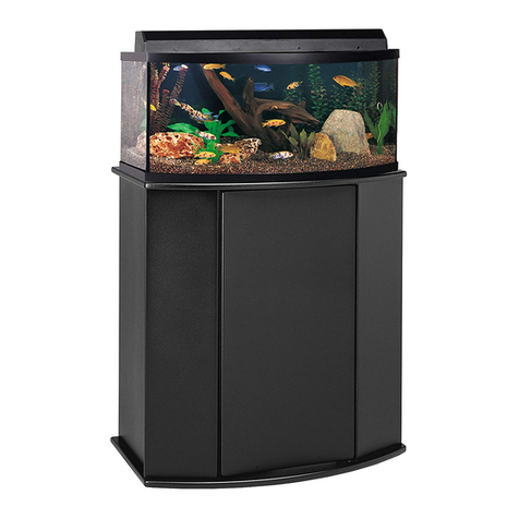
Cobalt Aquatics C-VUE 18 User manual


2
Door Hinges
Camlocks
Camlock Screws
½” Hinge Screws
1” Cabinet Foot Screws
Plastic Cabinet Feet
Stand Panels
C-VUE STAND PARTS LIST
Special Note on installing Camlock screws
When installing camlock screws into pre-installed
nylon adapters. Be sure not to over tighten, or cams
will not engage correctly.
Thread camlock screws straight up and down as
possible and only screw in just to the point where
you cannot see thread any more. If cam will not en-
gage during assembly, then you must unscrew the
camlock screw slightly until the head of the screw
and engage with cam.
Over tightening the camlock screws can also cause
damage to the outer nish of stand, this kind of
damage is not covered by warranty.

3
C-VUE 18, 26, 45 ASSEMBLY INSTRUCTIONS
• Insert two (2) Camlock Screws into the Right Side Panel.
• Be sure to screw in just until the threads are not visible, no more.
• Insert two (2) Camlocks into the Back Panel
• Attach Right Side Panel into the Back Panel
• Tighten Camlocks to secure the Right Side Panel to Back Panel.
• If cam will not engage during assembly, then you must unscrew the
camlock screw slightly until the head of the screw and engage with
cam.
Step 1- Attaching Right Side Panel to Back Panel
[requires two (2) Camlocks and two (2) Camlock Screws]

4
Step 2- Attach Le Side Panel to Back
Panel
[requires two (2) Camlocks and two (2)
Camlock Screws]
• Insert two (2) Camlock Screws into the
Le Side Panel.
• Be sure to screw in just until the
threads are not visible, no more.
• Insert two (2) Camlocks into the Back
Panel.
• Attach the Le Side Panel to the Back
Panel.
• Tighten Camlocks to secure the Le
Side Panel to Back Panel.
• If cam will not engage during as-
sembly, then you must unscrew the
camlock screw slightly until the head
of the screw and engage with cam.
Step 3- Attaching Bottom Panel to
Stand
[requires six (6) Camlocks and six (6)
Camlock Screws]
•Insert six (6) Camlock Screws into
the Bottom Panel.
•Be sure to screw in just until the
threads are not visible, no more.
• Insert two (2) Camlocks into the
Right Side Panel
• Insert two (2) Camlocks into the Le
Side Panel
• Insert two (2) Camlocks into the
Back Panel
• Attach Bottom Panel to Cabinet
• Tighten Camlocks to secure the
Bottom Panel to the Cabinet
• If cam will not engage during
assembly, then you must unscrew
the camlock screw slightly until the
head of the screw and engage with
cam.

5
Step 4- Attaching Front Panel to Stand
[requires two (2) Camlocks and two (2)
Camlock Screws]
• Insert two (2) Camlock Screws into the
Front Panel.
• Be sure to screw in just until the
threads are not visible, no more.
•Insert one(1) Camlocks into the Right
Side Panel
•Insert one (1) Camlocks into the Le
Side Panel
•Attach Front Panel to Cabinet
•Tighten Camlocks to secure the Bottom
Panel to the Cabinet
• If cam will not engage during assem-
bly, then you must unscrew the camlock
screw slightly until the head of the screw
and engage with cam.
Step 5- Attaching the Top Panel to the
Cabinet
[requires eight (8) Camlocks and eight (8)
Camlock Screws]
•Insert eight (8) Camlock Screws into the
Top Panel.
• Be sure to screw in just until the threads
are not visible, no more.
• Insert two (2) Camlocks into the Le Side
Panel
• Insert two (2) Camlocks into the Right
Side Panel
• Insert two (2) Camlocks into the Back
Panel
• Insert two (2) Camlocks into the Front
Support Brace
• Place the Top Panel on the Cabinet
Tighten the Camlocks to secure the Top
Panel to the Cabinet
• If cam will not engage during assembly,
then you must unscrew the camlock screw
slightly until the head of the screw and
engage with cam.

6
Step 6- Insert Shelf into stand
[requires four (4) shelf holders]
• Insert four (4) shelf holders into
pre-drilled holes.
• Press in rmly, you may need to
tap lightly with hammer.
• Place shelf onto shelf holders
Step 7- Attaching Hinges
[requires four (4) ½” screws]
• Attach the Hinges to the Le Side Panel and Right Side Panel
• Line up hinges with pilot holes and secure with 1/2” screws.
• Be sure to make screws with tight snug t, but do not over tighten.

7
Step 9- Installing the cabinet feet
[requires four [4] cabinet feet and four
(4) 1” cabinet feet screws]
• Align feet with pilot holes
• Secure with 1” screws.
• Be sure to make screws with tight
snug t, but do not over tighten.
Step 8- Installing the door
[requires four (4) ½” screws]
• Mount Door to the Hinge on the Side Panel using ½” screws.
• Line up hinges with pilot holes and secure with 1/2” screws.
• Be sure to make screws with tight snug t, but do
not over tighten.

8
C-VUE 40, 50 ASSEMBLY INSTRUCTIONS
• Insert two (2) Camlock Screws into the Right Side Panel.
• Be sure to screw in just until the threads are not visible, no more.
• Insert two (2) Camlocks into the Back Panel
• Attach Right Side Panel into the Back Panel
• Tighten Camlocks to secure the Right Side Panel to Back Panel.
• If cam will not engage during assembly, then you must unscrew the
camlock screw slightly until the head of the screw and engage with
cam.
Step 1- Attaching Right Side Panel to Back Panel
[requires two (2) Camlocks and two (2) Camlock Screws]

9
Step 3- Attaching Bottom Panel to
Stand
[requires eight (8) Camlocks and eight
(8) Camlock Screws]
•Insert eight (8) Camlock Screws into
the Bottom Panel.
•Be sure to screw in just until the
threads are not visible, no more.
• Insert two (2) Camlocks into the
Right Side Panel
• Insert two (2) Camlocks into the Le
Side Panel
• Insert four (4) Camlocks into the
Back Panel
• Attach Bottom Panel to Cabinet
• Tighten Camlocks to secure the
Bottom Panel to the Cabinet
• If cam will not engage during
assembly, then you must unscrew
the camlock screw slightly until the
head of the screw and engage with
cam.
Step 2- Attach Le Side Panel to
Back Panel
[requires two (2) Camlocks and two
(2) Camlock Screws]
• Insert two (2) Camlock Screws into
the Le Side Panel.
• Be sure to screw in just until the
threads are not visible, no more.
• Insert two (2) Camlocks into the
Back Panel.
• Attach the Le Side Panel to the
Back Panel.
• Tighten Camlocks to secure the
Le Side Panel to Back Panel.
• If cam will not engage during
assembly, then you must unscrew
the camlock screw slightly until
the head of the screw and engage
with cam.

10
Step 4- Attaching Front Panel to
Stand
[requires two (2) Camlocks and two
(2) Camlock Screws]
• Insert two (2) Camlock Screws
into the Front Panel.
• Be sure to screw in just until the
threads are not visible, no more.
•Insert one(1) Camlocks into the
Right Side Panel
•Insert one (1) Camlocks into the
Le Side Panel
•Attach Front Panel to Cabinet
•Tighten Camlocks to secure the
Bottom Panel to the Cabinet
• If cam will not engage during
assembly, then you must unscrew
the camlock screw slightly until
the head of the screw and engage
with cam.
Step 5- Attaching the Top Panel to the
Cabinet
[requires twelve (12) Camlocks and
twelve (12) Camlock Screws]
•Insert twelve (12) Camlock Screws into
the Top Panel.
• Be sure to screw in just until the
threads are not visible, no more.
• Insert two (2) Camlocks into the Le
Side Panel
• Insert two (2) Camlocks into the Right
Side Panel
• Insert four (4) Camlocks into the Back
Panel
• Insert four (4) Camlocks into the Front
Support Brace
• Place the Top Panel on the Cabinet
Tighten the Camlocks to secure the Top
Panel to the Cabinet
• If cam will not engage during
assembly, then you must unscrew the
camlock screw slightly until the head
of the screw and engage with cam.

11
Step 7-Installing middle support
beam.
[requires four (4) 1/2” screws and two
(2) angle brackets
• Place beam inside stand on front edge
and behind top front panel.
• Line up angle bracket with pilot holes
• Secure with 1/2” screws.
• Be sure to make screws with tight
snug t, but do not over tighten.
Step 6- Insert Shelf into stand
[requires four (4) shelf holders]
• Insert four (4) shelf holders into
pre-drilled holes.
• Press in rmly, you may need to
tap lightly with hammer.
• Place shelf onto shelf holders

12
Step 8- Attaching Hinges
[requires eight (8) ½” screws]
• Attach the Hinges to the Le Side Panel and Right Side Panel
• Line up hinges with pilot holes and secure with 1/2” screws.
• Be sure to make screws with tight snug t, but do not over tighten.
Step 9- Installing the doors
[requires eight (8) ½” screws]
• Mount Door to the Hinge on the Side Panel using ½” screws.
• Line up hinges with pilot holes and secure with 1/2” screws.
• Be sure to make screws with tight snug t, but do
not over tighten.

13
Step 10- Installing the cabinet
feet [requires four [4] cabinet
feet and four (4) 1” cabinet feet
screws]
• Align feet with pilot holes
• Secure with 1” screws.
• Be sure to make screws with
tight snug t, but do not over
tighten.

14
Cobalt International, Inc will warrant this product to be free of
manufacturer defects for a period of ninety (90) days. Co-
balt will repair or replace, at its option, any C-VUE aquarium
stand or component which is deemed defective in workman-
ship or materials. All warranty claims MUST be submitted
with a valid proof of purchase. This warranty does not cover
damage resulting from modications, misuse, negligence,
improper handling and installation, or incidental and/or con-
sequential damages resulting from the use of this product.
Any modication, including but not limited to cutting, drilling,
or changing out of parts to non-stock components, etc will
render this warranty void. Incidental and/or consequential
damages may include (but are not limited to):
If the stand is not placed on a at level surface, designed
to support the combined weight of the stand and aquarium
when lled. If an aquarium larger than that for which the
stand was designed is placed on the stand. If the stand is
moved without rst removing the aquarium, If the stand is
modied in any way from its original condition. If the stand
shows any damage due to water, impact, negligence, or
mishandling. If the stand is used for other than its intended
purpose.
Cobalt International is not responsible for and warranty does
not cover livestock loss (including but not limited to, sh,
plants, corals, live rock, other invertebrates, or aquarium
décor), personal injury, property loss, or damage (direct,
incidental, or consequential) resulting from the use of this
product. Use of this product indicates acknowledgement and
acceptance of these terms. This warranty gives you specic
legal rights. You may also have other legal rights that vary
from state to state*.
*Because some states do not allow the exclusion of incidental or consequential damages,
this exclusion may not apply to you.
Questions or Missing Parts:
WARRANTY

15
Please Fill Out Completely and Return within 14 days from date
of purchase. (Please Print)
Customer Name: _____________________________________
Address: ____________________________________________
City: ________________________________________________
State: ___________________Zip:_________________________
Phone#:______________________________________________
Email:____________________________________________
Yes I would like to receive emails on Cobalt News
New Products, Sales, Rebates
No I do not want receive emails on Cobalt News
Date of Purchase: ______________ Model_______________
Dealer Purchased From: ________________________________
Please mail warranty registration and Proof of Purchase to:
Cobalt International
Attn: Warranty Dept.—CVUE STAND
624 Wilkerson Rd
Rock Hill, South Carolina 29730
Complete this warranty card and return to Cobalt to obtain your ninety (90) day
warranty from date of purchase. Completed warranty cards can also be sub-
mitted electronically with proof of purchase to
WARRANTY REGISTRATION
Distributed By: Cobalt International
624 Wilkerson Rd
Rock Hill, South Carolina 29730
www.cobaltaquatics.com
Other manuals for C-VUE 18
1
This manual suits for next models
4
Table of contents
Other Cobalt Aquatics Aquarium manuals