Cobalt Digital Inc 3G Fusion 9921-FS User manual

9921-FS
2506 Galen Drive
Champaign, IL 61821
Voice 217.344.1243 • Fax 217.344.1245
www.cobaltdigital.com
Product Manual
9921-FS-OM (V1.18)
Cobalt Digital Inc.
3G/HD/SD-SDI
Frame Sync

Copyright
©Copyright 2016, Cobalt Digital Inc. All Rights Reserved.
Duplication or distribution of this manual and any information contained within is strictly prohibited without the express written
permission of Cobalt Digital Inc. This manual and any information contained within, may not be reproduced, distributed, or
transmitted in any form, or by any means, for any purpose, without the express written permission of Cobalt Digital Inc.
Reproduction or reverse engineering of software used in this device is prohibited.
Disclaimer
The information in this document has been carefully examined and is believed to be entirely reliable. However, no responsibility
is assumed for inaccuracies. Furthermore, Cobalt Digital Inc. reserves the right to make changes to any products herein to improve
readability, function, or design. Cobalt Digital Inc. does not assume any liability arising out of the application or use of any
product or circuit described herein.
Trademark Information
Cobalt®is a registered trademark of Cobalt Digital Inc.
FUSION3G®and COMPASS® are registered trademarks of Cobalt Digital Inc.
openGear®is a registered trademark of Ross Video Limited. DashBoard™ is a trademark of Ross Video Limited. Dolby®
encoder technology on this card is manufactured under license from Dolby Laboratories. Dolby®is a registered trademark of
Dolby Laboratories, Inc. Other product names or trademarks appearing in this manual are the property of their respective owners.
Linear Acoustic®, AEROMAX®, and UPMAX®are registered trademarks of Linear Acoustic, Inc. 2.0-to-5.1 audio upmixer
licensed feature uses the AutoMAX-II™ upmix algorithm provided under license from Linear Acoustic Inc. Loudness processor
licensed feature uses AEROMAX®algorithms provided under license from Linear Acoustic Inc. Linear Acoustic, the "LA"
symbol, AutoMAX, and AutoMAX-II are trademarks of Linear Acoustic Inc. All Rights Reserved.
Congratulations on choosing the Cobalt®9921-FS 3G/HD/SD-SDI Frame Sync. The 9921-FS is part of a full line of
modular processing and conversion gear for broadcast TV environments. The Cobalt Digital Inc. line includes video
decoders and encoders, audio embedders and de-embedders, distribution amplifiers, format converters, remote control
systems and much more. Should you have questions pertaining to the installation or operation of your 9921-FS, please
contact us at the contact information on the front cover.
Manual No.: 9921FS-OM
Document Version: V1.18
Release Date: December 29, 2016
Applicable for card
firmware version:
(or greater)
7207
Description of
product/manual
changes:
- Update manual to reflect product functional changes of latest firmware
release.
9921-FS-OM (V1.18)

9921-FS-OM (V1.18) 9921-FS PRODUCT MANUAL i
Table of Contents
Chapter 1 Introduction . . . . . . . . . . . . . . . . . . . . . . . . . . . . . . . . . . . . . . . . . . . 1-1
Overview ................................................................................................................ 1-1
9921-FS Card Software Versions and this Manual ................................................ 1-2
Cobalt Reference Guides........................................................................................ 1-2
Manual Conventions............................................................................................... 1-3
Warnings, Cautions, and Notes .................................................................. 1-3
Labeling Symbol Definitions...................................................................... 1-4
Safety Summary ..................................................................................................... 1-4
Warnings..................................................................................................... 1-4
Cautions...................................................................................................... 1-4
9921-FS Base Model and Options.......................................................................... 1-5
9921-FS Functional Description............................................................................. 1-6
9921-FS Video/Audio Signal Types........................................................... 1-6
9921-FS Video and Audio Options............................................................ 1-7
Video Subsystem Description .................................................................... 1-8
Audio Subsection Description.................................................................. 1-13
Control and Data Input/Output Interfaces ................................................ 1-21
User Control Interface .............................................................................. 1-22
9921-FS Rear Modules............................................................................. 1-24
Audio and Video Formats Supported by the 9921-FS ............................. 1-26
Technical Specifications....................................................................................... 1-26
Warranty and Service Information ....................................................................... 1-31
Cobalt Digital Inc. Limited Warranty....................................................... 1-31
Contact Cobalt Digital Inc.................................................................................... 1-32
Chapter 2 Installation and Setup . . . . . . . . . . . . . . . . . . . . . . . . . . . . . . . . . . . 2-1
Overview ................................................................................................................ 2-1
Setting I/O Switches for Analog Audio (1-8) Ports ............................................... 2-1
Installing the 9921-FS Into a Frame Slot................................................................ 2-2
Installing a Rear Module ........................................................................................ 2-4
9921-FS Rear Modules............................................................................... 2-7
Connecting To Phoenix Terminal Connectors ..................................................... 2-15
Setting Up 9921-FS Network Remote Control..................................................... 2-16
Chapter 3 Operating Instructions. . . . . . . . . . . . . . . . . . . . . . . . . . . . . . . . . . . 3-1
Overview ................................................................................................................ 3-1

ii 9921-FS PRODUCT MANUAL 9921-FS-OM (V1.18)
Control and Display Descriptions........................................................................... 3-1
Function Menu/Parameter Menu Overview................................................ 3-2
9921-FS Card Edge Controls, Indicators, and Display............................... 3-3
DashBoard™User Interface....................................................................... 3-4
Cobalt®Remote Control Panel User Interfaces .......................................... 3-5
Accessing the 9921-FS Card via Remote Control .................................................. 3-6
Accessing the 9921-FS Card Using DashBoard™..................................... 3-6
Accessing the 9921-FS Card Using a Cobalt®Remote Control Panel........ 3-7
Checking Card Information..................................................................................... 3-8
Ancillary Data Line Number Locations and Ranges .............................................. 3-9
9921-FS Function Menu List and Descriptions .................................................... 3-10
Video Input Control ................................................................................. 3-11
Video Proc/Color Correction ................................................................... 3-11
Timecode .................................................................................................. 3-15
Closed Captioning .................................................................................... 3-19
Framesync ................................................................................................ 3-21
AFD/WSS/VI ARC Controls ................................................................... 3-24
Video Output Crosspoint Control ............................................................ 3-30
Input Audio Status .................................................................................... 3-31
Audio Bus Input Routing/Controls .......................................................... 3-32
Output Audio Routing/Controls ............................................................... 3-42
Upmixing .................................................................................................. 3-47
COM and Metadata Routing .................................................................... 3-50
GPIO Controls .......................................................................................... 3-52
Presets ...................................................................................................... 3-54
Event Based Preset Loading ..................................................................... 3-55
Audio Routing with GPI Control Example............................................... 3-58
Troubleshooting .................................................................................................... 3-63
Error and Failure Indicator Overview....................................................... 3-63
Basic Troubleshooting Checks.................................................................. 3-67
9921-FS Processing Error Troubleshooting.............................................. 3-67
Troubleshooting Network/Remote Control Errors.................................... 3-70
What To Do If Your Card Locks Up......................................................... 3-70
In Case of Problems .................................................................................. 3-71

9921-FS-OM (V1.18) 9921-FS PRODUCT MANUAL 1-1
Chapter 1
Chapter 1 Introduction
Overview
This manual provides installation and operating instructions for the 9921-FS
3G/HD/SD Frame Sync card (also referred to herein as the 9921-FS).
This manual consists of the following chapters:
•Chapter 1, “Introduction”–Provides information about thismanual
and what is covered. Also provides general information regarding the
9921-FS.
•Chapter 2, “Installation and Setup”–Provides instructions for
installing the 9921-FS in a frame, and optionally installing 9921-FS
Rear Modules.
•Chapter 3, “Operating Instructions”–Provides overviews of
operating controls and instructions for using the 9921-FS.
This chapter contains the following information:
•9921-FS Card Software Versions and this Manual (p. 1-2)
•Manual Conventions (p. 1-3)
•Safety Summary (p. 1-4)
•9921-FS Base Model and Options (p. 1-5)
•9921-FS Functional Description (p. 1-6)
•Technical Specifications (p. 1-26)
•Warranty and Service Information (p. 1-31)
•Contact Cobalt Digital Inc. (p. 1-32)

19921-FS Card Software Versions and this Manual
1-2 9921-FS PRODUCT MANUAL 9921-FS-OM (V1.18)
9921-FS Card Software Versions and this Manual
When applicable, Cobalt Digital Inc. provides for continual product
enhancements through software updates. As such, functions described in this
manual may pertain specifically to cards loaded with a particular software
build. Cards loaded with initial software builds may not reflect all
functionality described in “9921-FS Functional Description”of this
chapter. Also note that some functions described here are options, and
may not appear on all 9921-FS cards.
The Software Version of your card can be checked by viewing the Card Info
menu in DashBoard™. See Checking Card Information (p. 3-8) in Chapter 3,
“Operating Instructions”for more information. You can then check our
website for the latest software version currently released for the card as
described below.
Check our website and proceed as follows if your card’s software does not
match the latest version:
Cobalt Reference Guides
From the Cobalt®web home page, go to Support>Reference Documents for
easy to use guides covering network remote control, card firmware updates,
example card processing UI setups and other topics.
Card Software earlier than
latest version Card is not loaded with the latest software. Not all
functions and/or specified performance described in
this manual may be available.
You can update your card with new Update software by
going to the Support>Firmware Downloads link at
www.cobaltdigital.com. Download “Firmware Update
Guide”, which provides simple instructions for
downloading the latest firmware for your card onto your
computer, and then uploading it to your card through
DashBoard™.
Software updates are field-installed without any
need to remove the card from its frame.
Card Software newer than
version in manual A new manual is expediently released whenever a
card’s software is updated and specifications
and/or functionality have changed as compared to
an earlier version (a new manual is not necessarily
released if specifications and/or functionality have not
changed). A manual earlier than a card’s software
version may not completely or accurately describe all
functions available for your card.
If your card shows features not described in this
manual, you can check for the latest manual (if
applicable) and download it by going to the card’s web
page on www.cobaltdigital.com.

9921-FS-OM (V1.18) 9921-FS PRODUCT MANUAL 1-3
Introduction Manual Conventions
Manual Conventions
In this manual, display messages and connectors are shown using the exact
name shown on the 9921-FS itself. Examples are provided below.
•Card-edge display messages are shown like this:
•Connector and control names are shown like this: AES I/O 8
In this manual, the terms below are applicable as follows:
•9921-FS refers to the 9921-FS 3G/HD/SD Frame Sync card.
•Frame refers to the 20-slot frame that houses the Cobalt®
COMPASS®and/or FUSION3G®cards.
•Device and/or Card refers to a COMPASS®and/or FUSION3G®
card.
•System and/or Video System refers to the mix of interconnected
production and terminal equipment in which the 9921-FS and other
COMPASS®and/or FUSION3G®cards operate.
•Functions and/or features that are available only as an option are
denoted in this manual like this:
Not all options are covered in this manual. In these cases, Manual
Supplement(s) for the option(s) ordered have been included in the
binder containing this manual.
Warnings, Cautions, and Notes
Certain items in this manual are highlighted by special messages. The
definitions are provided below.
Warnings
Warning messages indicate a possible hazard which, if not avoided, could
result in personal injury or death.
Cautions
Caution messages indicate a problem or incorrect practice which, if not
avoided, could result in improper operation or damage to the product.
Notes
Notes provide supplemental information to the accompanying text. Notes
typically precede the text to which they apply.
Ch01

1Safety Summary
1-4 9921-FS PRODUCT MANUAL 9921-FS-OM (V1.18)
Labeling Symbol Definitions
Safety Summary
Warnings
Cautions
Important note regarding product usage. Failure to observe may result in
unexpected or incorrect operation.
Electronic device or assembly is susceptible to damage from an ESD event.
Handle only using appropriate ESD prevention practices.
If ESD wrist strap is not available, handle card only by edges and avoid contact
with any connectors or components.
Symbol (WEEE 2002/96/EC)
For product disposal, ensure the following:
•Do not dispose of this product as unsorted municipal waste.
•Collect this product separately.
•Use collection and return systems available to you.
! WARNING ! To reduce risk of electric shock do not remove line voltage service barrier cover on frame
equipment containing an AC power supply. NO USER SERVICEABLE PARTS INSIDE.
REFER SERVICING TO QUALIFIED SERVICE PERSONNEL.
CAUTION This device is intended for environmentally controlled use only in appropriate video
terminal equipment operating environments.
CAUTION This product is intended to be a component product of an openGear® frame. Refer to the
openGear® frame Owner's Manual for important safety instructions regarding the proper
installation and safe operation of the frame as well as its component products.
CAUTION Heat and power distribution requirements within a frame may dictate specific slot
placement of cards. Cards with many heat-producing components should be arranged to
avoid areas of excess heat build-up, particularly in frames using only convection cooling.
The 9921-FS has a moderate power dissipation (20 W max.). As such, avoiding placing the
card adjacent to other cards with similar dissipation values if possible.
CAUTION If required, make certain Rear Module(s) is installed before installing the 9921-FS into the
frame slot. Damage to card and/or Rear Module can occur if module installation is
attempted with card already installed in slot.
CAUTION If card resists fully engaging in Rear Module mating connector, check for alignment and
proper insertion in slot tracks. Damage to card and/or Rear Module may occur if improper
card insertion is attempted.

9921-FS-OM (V1.18) 9921-FS PRODUCT MANUAL 1-5
Introduction 9921-FS Base Model and Options
9921-FS Base Model and Options
(See Figure 1-1.) The base model 9921-FS provides Linear Acoustic®
loudness processing with frame sync, video processing, embedded audio
support, and timecode support. Options add various I/O, video, and audio
expanded capabilities to the base model as shown in Figure 1-1 and described
below. The various options are described in detail in 9921-FS Video and
Audio Options (p. 1-7), and as applicable throughout this manual.
Figure 1-1 9921-FS Simplified Overview of Base and Option Features/Functions
Restore entire page from rgl
Base Features/Functions
• 3G/HD/SD-SDI coax (BNC) input/
output
• Advanced audio processing with
full routing, gain, and delay control
• Video Proc controls
• Per-channel audio-video delay
control
• Frame sync with reference
selectable from multiple sources
• SMPTE timecode support, with
translation across formats
• GPI ports with user-definable
functions
• Centralized GUI remote control
using DashBoard™ software and
Cobalt OGCP-9000 Remote
Control Panels
Option Features/Functions
• 3G/HD/SD-SDI Fiber input/output.
Blind mate interface allows card
swapping with nocable
disconnection.
• Passive relay bypass for SDI coax
input/output path
• Linear Acoustic® loudness
processing and automatic upmixing
• Universal HD/SD analog video
input. 3D comb decoder on analog
video input. Composite video
output is color-framed to match
reference burst, plus user offset.
• Wings insertion and
general-purpose keying
• AES ports GUI-selectable as input
or output. Independent SRCs for
each input.
• Analog audio inputs and outputs.
Full 24-bit conversion.
• Complete Dolby®E/AC-3encoder
and decoder options
Frame
Sync
Audio
Proc
VANC Data
Controls
Wings/
Keying
Support*
Video Proc
Color
Correction*
3G/HD/SD-SDI (BNC)
3G/HD/SD Fiber*
AES Audio*
Analog Audio*
Analog Video*
3G/HD/SD-SDI (BNC)
3G/HD/SD Fiber*
AES Audio*
Analog Audio*
Analog Video*
Input
Video
Routing
Audio
Mux/
De-mux/
Routing
Output
Video
Routing
Audio
Mux/
De-mux/
Routing
16-Channel Internal Audio Bus
* denotes option

19921-FS Functional Description
1-6 9921-FS PRODUCT MANUAL 9921-FS-OM (V1.18)
9921-FS Functional Description
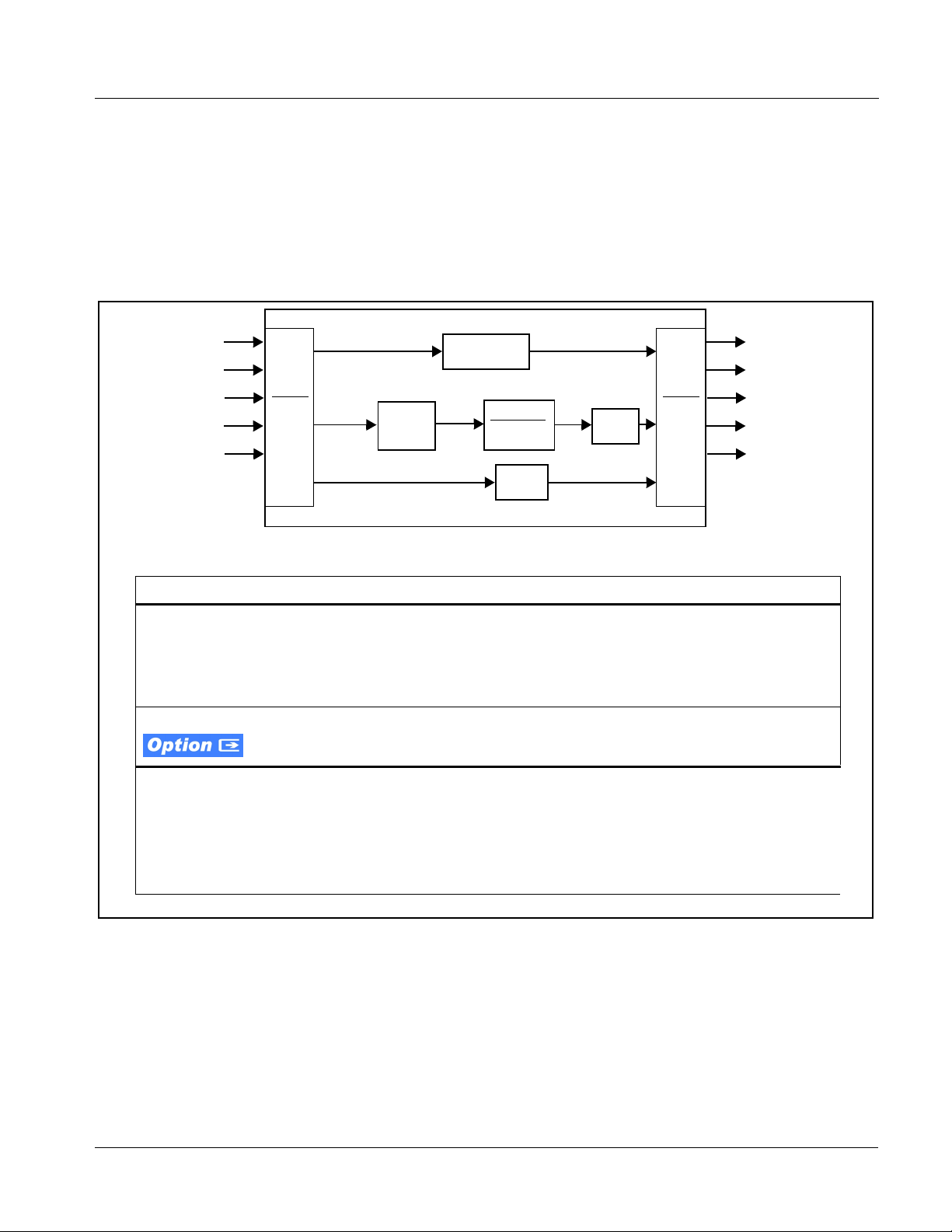
Figures 1-3 and 1-5 show functional block diagrams of the 9921-FS video/
control and audio subsystems, respectively.
9921-FS Video/Audio Signal Types
Table 1-1 lists the video/audio inputs and outputs (available via rear module
connections) provided by the 9921-FS. Note that some signal types are
supported through the use of options, and also require a rear module that
supports the connections described here; the complete option/rear module
requirement is specified in Table 1-1.
Table 1-1 9921-FS Video/Audio Signal Types
Signal ID Description Option/Rear Module
Package Required
SDI IN A thru SDI IN D Four 3G/HD-SD-SDI BNC video
inputs; routable to card processing
via input crosspoint
SDI IN A is standard. Other inputs
are active when options are installed
(such as wings and keyer)
❑Various Rear Modules offer various
SDI BNC input complements. See
9921-FS Rear Modules (p. 2-7) for
more information.
Fiber Rx-A I/O,
Fiber Rx-B I/O Up to two 3G/HD-SD-SDI fiber LC
video inputs; routable to card
processing via input crosspoint
•Option +FRx (1 Fiber input)
•Option +FRx/Tx (1 Fiber input; 1
Fiber output)
•Option +FRx/Rx (2 Fiber inputs)
❑Requires Expansion Rear Module
supporting fiber I/O. See 9921-FS
Rear Modules (p. 2-7) for more
information.
AES Audio IN/OUT (1-16) Eight AES 3-id BNC pairs; each pair
user GUI-selectable as either input
or output. Independent SRC for each
input, with auto/manual SRC bypass
for non-PCM data.
•Option +AES
❑Various Rear Modules offer various
number of AES pairs supported.
See 9921-FS Rear Modules (p.
2-7) for more information.
Analog Video/Audio I/O Up to eight balanced analog audio
channels (using Phoenix™3-wire
terminations); each channel
switch-selectable as either input or
output.
HD/SD composite and component
analog I/O
Refer to option Manual Supplement
OPT-F3GAN-MS for descriptions of
analog video/audio I/O options
available.
SDI OUT A thru SDI OUT D Four 3G/HD-SD-SDI BNC video
outputs; routable from card
processing via output crosspoint
Standard
❑Various Rear Modules offer various
SDI BNC output complements.
See 9921-FS Rear Modules (p.
2-7) for more information.
Note: The input/output complement listed above and shown in Figures 1-3 and 1-5 represents the maximum capability of the 9921-FS.
The practical input/output complement is determined by the particular Rear Module used with the 9921-FS. Not all options are
available concurrently on a single card.

9921-FS-OM (V1.18) 9921-FS PRODUCT MANUAL 1-7
Introduction 9921-FS Functional Description
9921-FS Video and Audio Options
In addition to the I/O options described in Table 1-1 above, the 9921-FS
offers several video and audio options described in Table 1-2. Note that
several options also require a rear I/O option that supports the video and/or
audio options described here; the complete option requirement is specified in
Table 1-2.
Table 1-2 9921-FS Video/Audio Options
Option Description Option/Rear Module Package
Required
Note: Options are periodically added for this card. Check for latest options on the card web page at cobaltdigital.com. Most
options, in addition to licensing, require that card be loaded with the latest available firmware.
Video Options
Color Correction In addition to standard video proc controls,
provides independent RGB channel controls
for luma, black, and gamma.
•Option +COLOR
Wings Insertion Provides wings insertion using an independent
SDI input provided for wings insertion, with
software-configurable insertion width/pan
controls.
Refer to option Manual Supplement
OPT-SW-F3GWINGS-MS for
description and signal connection
information.
Keying Provides keying using independent SDI inputs
for key and fill signals. Also provides a
separate dedicated key preview SDI output.
Refer to option Manual Supplement
OPT-F3KEY-MS for description and
signal connection information.
Audio Options
Note: Software options below can be field-installed on a card without removal of the card from its frame.
LinearAcoustic®Loudness
Processing function Linear Acoustic®AEROMAX®5.1-channel or
stereo audio output loudness processing can
be added.
•Option +LP5.1 (5.1-Ch loudness
processing)
•Option +2LP2.0 (dual independent
stereo loudness processing)
•Option +LP2.0 (stereo loudness
processing)
OGCP Loudness Meter
software
(Note 1)
5.1-channel loudness meter in accordance with
EBU R128, ATSC A/85 and ITU BS.1770.
Allows OGCP-9000 to provide user interface.
•Option +LM
Linear Acoustic®Upmixing
software
(Note 2)
Linear Acoustic®AUTOMAX™converts legacy
stereo program audio (from any source
received by the card) to 5.1-channel audio.
•Option +UM
Automatic Downmixing Provides a stereo downmix from selected
alternate multi-channel sources if selected
primary L/R channels lose signal.
•Option +ADM
Automatic Audio Failover Provides failover to alternate (“secondary”)
channels to substitute for the primary channels
in the event of audio signal loss.
•Option +AFO

19921-FS Functional Description
1-8 9921-FS PRODUCT MANUAL 9921-FS-OM (V1.18)
Video Subsystem Description
Note: Descriptions below include some functions and features that are available
only as options.
(See Figure 1-3.) The 9921-FS features a frame sync that can select from
either of two card frame reference sources, input video, or free-run (internal
clock) video sync. In the event of input video loss of signal, the output can be
set to disable video, go to black, go to an internal test signal generator pattern,
or freeze to the last intact frame (last frame having valid SAV and EAV
codes).
Video Processor
The 9921-FS provides full color processing control (luma gain and lift,
chroma saturation, and color phase) of the output video. The color correction
option (+COLOR) provides independent RGB channel controls for luma,
black, and gamma. The color correction function converts the YCbCr SDI
input video to the 4:4:4 RGB color space (where the color correction is
applied), and then back to YCbCr SDI on the output of the function. Controls
are available to adjust each RGB level independently for both white levels
(gain) and black levels (offset). Gamma can also be independently adjusted
for each RGB channels. Various controls can be ganged to provide adjustment
for all three color channels simultaneously.
The color correction function can be user-selected to be applied to input video
or output video as shown in Figure 1-3.
Dolby®E/AC-3 Decoding Provides Dolby®E and/or AC-3 decoding from
embedded and AES sources. •Option +DEC
❑If serial metadata Rx/Tx support is
needed, requires Rear Module
with RS-485 port
Dolby®Digital (AC-3)
Encoding
(Note 3)
Provides Dolby®AC-3 encoding from any
audio source used by the card (including mixed
and loudness-processed audio).
Accommodates internally generated and
external metadata.
•Option +ENCD
❑If serial metadata Rx/Tx support is
needed, requires Rear Module
with RS-485 port
Dolby®E Encoding
(Note 3) Provides Dolby®E encoding from any audio
source used by the card (including mixed and
loudness-processed audio). Accommodates
internally generated and external metadata.
•Option +ENCE
❑If serial metadata Rx/Tx support is
needed, requires Rear Module
with RS-485 port
Notes: 1. This option must be used in conjunction with a Cobalt®OGCP-9000 Remote Control Panel. The control panel serves as the
control/display portal.
2. Option +UM can be used in conjunction with Loudness Processing options.
3. Dolby®AC-3 and E encoding cannot be accommodated concurrently within the same card.
Table 1-2 9921-FS Video/Audio Options — continued
Option Description Option/Rear Module Package
Required

9921-FS-OM (V1.18) 9921-FS PRODUCT MANUAL 1-9
Introduction 9921-FS Functional Description
Frame Sync Function
This function provides for frame sync control using either one of two external
FRAME REF IN (1,2) reference signals distributed with the card frame, or the
input video as a frame sync reference.
This function also allows horizontal and/or vertical offset to be added
between the output video and the frame sync reference.
Frame sync can select from either of two card frame reference sources, or
free-run input video sync. Selectable failover allows alternate reference
selection should the initial reference source become unavailable or invalid. In
the event of input video loss of signal, the output can be set to disable video,
go to black, go to an internal test signal generator pattern, or freeze to the last
intact frame (last frame having valid SAV and EAV codes).
An internal test signal generator provides a selection of 10 standard patterns
such as color bars, sweep patterns, and other technical patterns. The generator
output can be invoked upon loss of program video input, or applied to the
program video output via user controls.
ARC Processor
(See Figure 1-4.) This function uses extracted Aspect Ratio Control (ARC)
data from the input video (in either AFD, WSS, or VI formats) and provides:
•Format translation between AFD, WSS, and VI ARC formats.
•H/V cross-conversion matrix in which a received code directs a same
or other user-selectable alternate H/V ratio on the output for any of
several H/V ratios.
•(Scaler-equipped card only) Directs scaler automatic active ARC in
response to received and/or converted ARC code (Scaler Follows
ARC).
The input video is checked for ARC formats and can be set to provide a
trigger upon when a selected ARC format is received, the code associated
with the received format can be applied to the output as a translated format
(for, example, from WSS to AFD). Received H/V codes can also be applied
through an H/V conversion matrix that allows alternate H/V ratios for a given
received input code. The ARC code format priority works in that AFD has
highest priority, with WSS or VI selectable as the next priority. In conjunction
with a user-accessible cross-matrix table, the received code then in turn
directs any of several user-selectable H/V settings to be inserted on the output
video as AFD, WSS, and/or VI codes. AFD, WSS and/or VI can be rejected
for input consideration. On cards equipped with a scaler, the selected output
H/V ratio can be set to automatically apply this aspect ratio to the program
video.

19921-FS Functional Description
1-10 9921-FS PRODUCT MANUAL 9921-FS-OM (V1.18)
Figure 1-2 ARC Processor
Wings Insertion
Option +WINGS allows a symmetrical L-R wings insertion to be integrated
into the card program video output. Wings video is accommodated using a
separate wings SDI input. The wings user interface displays wings timing
relative to the card output video, allowing wings timing offset to be adjusted
such that wings can be properly framed. (The option and its host card does not
provide timing offset control of the wings video; offset must be provided by a
external frame sync card or device controlling the wings video feed.)
The wings L/R insertion width can be manually configured, or can be set to
automatically track with aspect ratio as set by the host card (on cards
equipped with aspect ratio control).
Format
Detect/
Select
Output
ARC
Cross-
Matrix
Program
Video
Input
AFD Generate/
Insert Control
WSS Generate/
Insert Control
VI Generate/
Insert Control
Scaler ARC Command
(Note 1)
AFD
WSS
VI
Program
Video
Output
Note: 1. ActiveARCcontrolavailableonlywith
card equipped with scaler. On
non-scaler card, ARC control/convert
function only manipulates output SDI
ARC codes and has no local effect on
card output aspect ratio.
2. Line number control available only
for AFD format. WSS and VI use
fixed line numbers per applicable
standards.
3. Some AFD codes are not supported
in VI and WSS formats.

9921-FS-OM (V1.18) 9921-FS PRODUCT MANUAL 1-11
F9985_VID4_11
PGM VID IN
HD/SD
Analog
Video IN
Audio
Demux
De-embed audio to
audio subystem
Video
Filter/
ADC
Y/Cmpst IN
Pb/C IN
Pr IN
Video Proc/
Color Correction
ANC
Extract/
Processing
ANC Control/
Re-Insert
Video Framesync/
H-V Offset
Program
Video
ANC
Wings
Insertion
Keying
Control/
Insertion
KEY VID IN
FILL VID IN
Audio
Mux
Audio from audio
subsystem
Output Video
Crosspoint
PROGRAM VIDEO
KEY PREVIEW
RCLK INPUT VID
HD/SD
Analog
Video
OUT
Video
DAC
Y/Cmpst OUT
Pb/C OUT
Pr OUT
Serialize
SDI OUT A
SDI OUT B
SDI OUT C
SDI OUT D
Cable
Drivers
EQ
Frame Ref
Select/Failover
FRAME REF IN 1
FRAME REF IN 2
Audiooffsetcontrol
to audio subystem
Y-channel analog VANC
WINGS VID IN
Fiber
Rx
Rx A
Rx B
FIBER Rx-A IN
FIBER Rx-B IN
SDI IN A
SDI IN B
SDI IN C
SDI IN D
Input
Deserialize/
Select
Crosspoint
Fiber
Tx
Tx A
Tx B
FIBER Tx-A OUT
FIBER Tx-B OUT
Serialize
(NOTE 4)
Relay
Bypass
(NOTE 6)
Timecode and
Closed Captioning
Processors
TC/CC ANC
Data In TC/CC ANC
Data Out
Network Remote
Control
Ethernet 10/100 (on frame)
Serial Rx/Tx
Interface
COM 1, 2 (Metadata I/O; RS-485 LTC I/O)
GPI
GPI 1,2
Reclock
Figure 1-3 9921-FS Video/Control Block Diagram
Notes: 1. All video input/outputs are 3G/HD/SD-SDI coaxial unless otherwise specified.
2. Some functional blocks shown are available only as options. Refer to text.
3. Refer to 9921-FS Audio Block Diagram for audio embed/de-embed/routing audio subsystem.
4. Reclocked input video fed to the Output Video Crosspoint is available only from SDI IN A input.
5. Input/output complement shown depicts full capacity. Practical I/O complement is determined by I/O module(s),
options package, and card firmware version.
6. Optional relay bypass provides fully passive failover located on rear module. Card presence not required for
passive failover connection. Relay bypass is available only between the SDI IN B and SDI OUT B ports.

19921-FS Functional Description
1-12 9921-FS PRODUCT MANUAL 9921-FS-OM (V1.18)
Timecode Processor
(See Figure 1-4.) This function uses extracted timecode data from the input
video (waveform or ATC), reference VITC waveform, or internal (free run)
and in turn re-inserts selected timecode data into the program video signal.
The function can monitor video input and reference input for supported
timecode formats, and then select and prioritize among SDI VITC waveform,
SDI ATC_VITC, and SDI ATC_LTC timecode sources. If the preferred
format is detected, the preferred format is used by the card; if the preferred
format is not detected, the card uses other formats (where available) as
desired.
The function also provides conversion between various timecode formats and
provides independent insertion and line number controls for each SDI
timecode output format. When licensed with option +LTC, this function also
can receive, send and translate between audio/RS-485 LTC timecode formats
and the VBI formats described above. Refer to catalog or Fusion3G®manual
supplement OPT-F3GLTC-MS for more information.
Figure 1-4 Timecode Processor
Frame
Reference
SDI VITC
Waveform
Detect/Extract
SDI ATC_LTC
Detect/Extract
SDI ATC_VITC
Detect/Extract
Priority/
Select
Program
Video
Input
SDI VITC
Timecode
Proc/Embed
ATC_VITC
Timecode
Proc/Embed
ATC_LTC
Timecode
Proc/Embed
Insert
Control
Line
Number
Control
Buffer/
Format
3G/HD/SD–SDI
(From UDX Scaler)
Free Run
(Internal Count)
Ref VITC
Waveform
Detect/Extract
Audio LTC
Select/Extract
Audio/
RS-485 LTC Audio/RS-485
LTC Generate
Audio LTC Out
RS-485 LTC Out

9921-FS-OM (V1.18) 9921-FS PRODUCT MANUAL 1-13
Introduction 9921-FS Functional Description
Closed Captioning Processor
This function provides support for closed captioning setup. When enabled,
the function allows passage of timecode data. The function also allows the
selection of the ancillary data line number where the ancillary closed caption
data is outputted when the output is HD.
Video Output Crosspoint
A four-output video matrix crosspoint allows independently applying the card
video processing paths (PROGRAM VIDEO, KEY PREVIEW, RECLOCKED) to
any of the four card discrete coaxial outputs (SDI OUT A thru SDI OUT D).
A video D/A converter provides either composite or component analog video
outputs of program video using choices from several formats appropriate for
SD or HD analog video.
Notes: •Rear Module relay bypass is available only between the SDI OUT B and
SDI OUT B ports. This is a passive bypass and does not require card opera-
tion or presence for bypass.
•Output reclocked video can only be obtained from SDI input SDI OUT A.
Audio Subsection Description
Note: Descriptions below include some functions and features that are available
only as options.
(See Figure 1-5.) The 9921-FS audio processing subsection is built around a
card internal 16-channel bus. This 16-channel bus receives inputs from an
input routing crosspoint that routes de-embedded and discrete AES signals
over the 16-channel bus. Correspondingly, at the output end of the 16-channel
bus is an output routing crosspoint that in turn distributes the 16-channel bus
signals to embedded and discrete AES audio outputs.
An Input Audio Status display shows the presence and peak level of each
input audio channel received by the card. For digital audio inputs, payload is
identified (PCM or data such as Dolby®Digital or E), as well as sample rate
for discrete AES inputs. Discrete AES inputs can have sample rate conversion
applied to align these inputs with the output timing (received sample rates
from 32 kHz to 96 kHz are supported).
An Audio DSP function (which interfaces with the output routing block)
provides eight tone generators and advanced functions such as loudness
processing and upmixing. The routing and AudioDSP functions are described
in detail later in this section.

19921-FS Functional Description
1-14 9921-FS PRODUCT MANUAL 9921-FS-OM (V1.18)
As such, the audio subsection provides a full crosspoint between all supported
audio inputs and output formats. The audio subsection allows choices from
the following audio inputs:
•16 channels of de-embedded audio from the SDI program video path
•Up to 16 channels (8 pairs) of discrete AES input
•Up to 8 channels of balanced analog audio input
•Up to 10 channels of decoded Dolby®E or AC-3 audio
•Digital silence (mute) setting
The audio subsection allows routing to the following audio outputs:
•16 channels of embedded audio on the SDI output
•Up to 16 channels of discrete AES output on eight AES pairs
•Up to 8 channels of balanced analog audio output
Note: Practical AES channel count handled by the card is 8 pairs, of which each
pair can be user GUI-selectable as an input or output.
All embedded and AES channels have status displays that show the following
for each channel pair:
•PCM signal presence
•Dolby E signal presence
•Dolby Digital signal presence
•Missing (no signal detected)
Embedded, AES, and analog input channel pairs also have displays showing
slow-ballistics true peak levels for each pair. Embedded and AES channels at
digital silence signal level show Mute; analog channels with levels below -96
dBFS digital equivalent show Silence.
Output audio rates are always 48 kHz locked to output video, but discrete
AES inputs can pass through the sample rate converters to align these inputs
with the output timing. Output AES is always precisely synchronized with the
output video. The balanced analog audio input is sampled at 48 kHz with a
+24 dBu clipping level (+24 dBu => 0 dBFS).
Note: AES Dolby-encoded inputs routed directly to card optional Dolby decoder are
detected and use a special path that automatically bypasses SRC.

9921-FS-OM (V1.18) 9921-FS PRODUCT MANUAL 1-15
De-Embed IN 1-16
(from Program
Video De-Embed)
AES
Rcvr/SRC
AES IN 1-16
Input Routing
Dolby®
Decode
Decoded
PCM Audio
Program Audio
Dolby E or AC-3
Encoded Audio
A/V Delay
Offset
Control
Gain/Mute
Control
Emb OUT 1-16
(to Program
Video Embed)
Output Routing
2-Ch LP-A
2-Ch LP-B
5.1-Ch LP
DSP
Upmixer
Tone Gen
Output
Dolby®
Encode Dolby E or
AC-3
Encoded
Program
Audio
PCM IN
Internal Bus Controls
AES Port
Direction
Control
AES IN/OUT
1-16
Input Output
Ref
F99XXR-UDX_AUD 10-11
Input Output
AES OUT 1-16
Internal Bus
Analog
Audio A/D
ANLG AUD
IN/OUT 1-8
Analog
Audio
Direction
Control
DIP Bank
ANLG AUD IN 1-8
ANLG AUD OUT 1-8
Analog
Audio D/A
AES Out
1-16
ANLG Out
1-8
Downmix (4)
Flex Mix
Loudness Meter 1
Loudness Meter 2
Notes: 1. Refer to 9921-FS Video Block Diagram for video, reference, and control subsystem.
2. Input/output complement shown depicts full capacity. Practical I/O complement is determined by Rear
Module(s) and options package.
3. Dolby®decoder option supports both Dolby E and AC-3 streams. Dolby®encoder option available as
Dolby E and/or Dolby Digital. Dolby Digital option supports multiple AC-3 stream encoding.
4. Audio DSP block shows full capacity. Practical complement is determined by ordered options package.
LP=Loudness Processor; LM=Loudness Meter; Tone Gen=Tone Generators.
Figure 1-5 9921-FS Audio Block Diagram

19921-FS Functional Description
1-16 9921-FS PRODUCT MANUAL 9921-FS-OM (V1.18)
.Audio Input Routing/Mixing Function
(See Figure 1-5.) The input routing function provides gain and mute controls
for each input signal. Following these controls, selected inputs can directly
exit the input routing function and be applied to the internal bus, or first be
applied to one of four downmixers or flex mixers.
Downmixers. (See Figure 1-6.) Four independent downmixers (Downmix-A
thru Downmix-D) provides for the selection of any five embedded, AES
discrete, Dolby®decoded, or analog audio sources serving as Left (L), Right
(R), Center (C), Left Surround (Ls), and Right Surround (Rs) individual
signals to be multiplexed into a stereo pair. The resulting stereo pairs
Downmix-A(L/R) thru Downmix-D(L/R) can in turn be routed and processed just
like any of the other audio sources described earlier.
Figure 1-6 Downmixing Functional Block Diagram with Example Sources
Automatic Downmixer. Automatic downmixing (option
+ADM) allows monitoring a selected stereo pair for a user-configurable signal
level threshold. If this threshold is not achieved within a configurable holdoff
time, the automatic downmixing develops a stereo downmix from selected
alternate multi-channel sources (developing an automatic downmix as
described for Downmixers above).
Flex Mixer. The flex mixer is a flexible-structure mixer in which any of 16
summing nodes (Flex Mix Bus A thru Flex Mix Bus P) can be applied to any of
the 16 inputs, thereby allowing several customizable mixing schemes. Any
individual input row can be assigned to any of the Flex Mix buses.
Using this scheme, full cross-point mixing of PCM signals can be achieved
within the limit of available Flex Mix buses, and eventually applied to any of
the internal bus channels. Figure 1-7 shows an example of two independent
3-to-1 mono mixers availed by setting inputs (rows) 1 thru 3 to use virtual
flex mix bus Flex Mix Bus A, and by setting inputs 4 thru 6 to use virtual flex
mix bus Flex Mix Bus B. The Flex Mix A and Flex Mix B virtual outputs can then
be routed over any of the internal bus channels. In this example, because rows
1 thru 3 are all applied in common to mixer node Flex Mix Bus A, the Flex Mix
Bus A output is the mono-mixed sum of these inputs. The mono mix on the
Flex Mix Bus B node similarly produces a mono mix of input rows 4 thru 6.
Downmix-A(L)
Ls
L
C A
R
Rs
Downmix-A(R)
Embedded Ch 1
Embedded Ch 2
AES Ch 6
Embedded Ch 4
Embedded Ch 5
AES Ch 1 - Ch 16
AN-AUD Ch 1- Ch 8
Embed Ch 1 - Ch 16
To Internal Bus
Table of contents
Other Cobalt Digital Inc Sound Card manuals