COBHAM CAES UT65CML8X8FD-EVB-UM User manual

4350 Centennial Blvd. | Colorado Springs CO 80907 USA | 1-800-645-8862 | caes.com
3.125 Gbps Crosspoint Switch (XPS)
UT65CML8X8FD-EVB-UM Evaluation Board
4/06/2022
USER MANUAL
1.0 Introduction
The UT65CML8X8FD-EVB Evaluation Board provides a comprehensive platform for evaluating the UT65CML8X8FD
3.125 Gbps Crosspoint Switch (XPS). The XPS is configured via the internal registers as specified in the register map
section of the data sheet. Internal registers are configured via the XPS SPI port. A Software (SW) Graphical User
Interface (GUI) is provided with the UT65CML8X8FD-EVB to facilitate setup of the XPS device. Users can specify
high-speed signal routing paths, input receiver (RX) equalization (EQ), output transmitter (TX) amplitude, and all
other User-configurable operating parameters through the SW GUI. This User Guide serves to provide setup and
operation of the UT65CML8X8FD-EVB, including both Hardware (HW) and Software (SW).
Figure 1: UT65CML8X8FD-EVB Crosspoint Switch Evaluaton Board
Top View (TX Side)

4350 Centennial Blvd. | Colorado Springs CO 80907 USA | 1-800-645-8862 | caes.com
3.125 Gbps Crosspoint Switch (XPS)
UT65CML8X8FD-EVB-UM Evaluation Board
4/06/2022
USER MANUAL
2.0 Reference Documents
Description
Reference Document
UT65CML8X8FD XPS
1) Data Sheet
https://caes.com/products/radiation-hardened-solutions-high-reliability-
components/interconnect/crosspoint-switch
https://caes.com/sites/default/files/documents/Datasheet-UT65CML8X8FD.pdf
UT65CML8X8FD-EVB
1) PCB Layout Information
2) EVB GUI SW
3) EVB User Manual
https://caes.com/product/ut65cml8x8fd#downloads
3.0 Evaluation Kit Contents
UT65CML8X8FD-EVB 3.125 Gbps Crosspoint Switch (XPS) Evaluation Board (EVB) (1) –Populated with SMA
Jacks + AC-Coupling Capacitors for 1 of 4 Channels Only: Channel 1 for All Ports 0-3.
UT65CML8X8FD-EVB XPS Evaluation Board GUI Software (1)
National Instruments (NI) USB-6501 USB-to-SPI Interface Device (1)
USB AB 2.0 Cable (1) –Laptop PC to NI USB-6501 USB Interface
NI USB-6501 SPI Interface Custom Cable Assembly (1) - NI USB-6501 to EVB SPI Port Interface
UT65CML8X8FD-EVB-UM Evaluation Kit User Manual (1)

4350 Centennial Blvd. | Colorado Springs CO 80907 USA | 1-800-645-8862 | caes.com
3.125 Gbps Crosspoint Switch (XPS)
UT65CML8X8FD-EVB-UM Evaluation Board
4/06/2022
USER MANUAL
4.0 Table of Contents
Table of Contents
1.0 Introduction ........................................................................................................................................... 1
Figure 1: UT65CML8X8FD-EVB Crosspoint Switch Evaluaton Board Top View (TX Side) ................................... 1
2.0 Reference Documents ............................................................................................................................. 2
3.0 Evaluation Kit Contents ........................................................................................................................... 2
4.0 Table of Contents ................................................................................................................................... 3
5.0 Evaluation Board (EVB) Configuration....................................................................................................... 4
Figure 2: UT65CML8X8FD-EVB Crosspoint Switch Evaluaton Board –Top View (TX Side) Mounted with C-BGA
Proto DUT................................................................................................................................................... 4
Figure 3: UT65CML8X8FD-EVB Crosspoint Switch Evaluaton Board –Bottom View (RX Side)............................ 5
6.0 Test Equipment List ................................................................................................................................ 6
7.0 Test Equipment setup diagram ................................................................................................................ 7
Figure 4: Test Equipment Setup Diagram...................................................................................................... 7
8.0 Operating Instructions............................................................................................................................. 8
Figure 5a: Evaluation Board Test Configuration –All Possible XPS Connections ............................................... 8
Figure 5b: Evaluation Board Test Configuration –Default XPS Connections ..................................................... 9
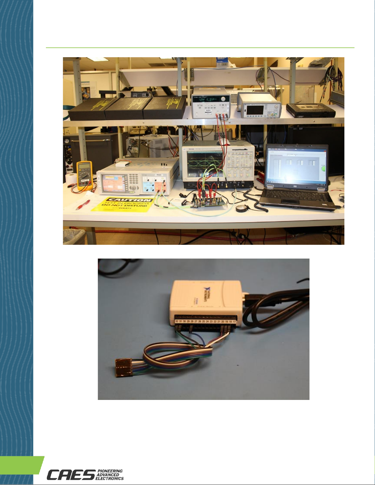
Figure 6: Example UT65CML8X8FD-EVB Test Equipment Setup .....................................................................10
Figure 7: NI USB-6501 USB-to-SPI Interface Device with Interface Cable.......................................................10
Figure 8: Detailed View of EVB Master SPI Port Header + Cable Assembly Connector Interface.......................11
Figure 9: XPS GUI “Miscellaneous” Settings Tab Parameters .........................................................................12
Figure 10: XPS GUI “Receiver (RX)” Settings Tab Parameters........................................................................12
Figure 11: XPS GUI “Transmitter (TX)” Settings Tab Parameters ...................................................................13
Figure 12: Schematics 1/5 .........................................................................................................................14
Figure 13: Schematics 2/5 .........................................................................................................................15
Figure 14: Schematics 3/5 ..........................................................................................................................16
Figure 15: Schematics 4/5 ..........................................................................................................................17
Figure 16: Schematics 5/5 ..........................................................................................................................17
Figure 17: Bill of Materials (BoM).................................................................................................................19
11.0 EVB Layout Information........................................................................................................................20
12.0 Revision History ...................................................................................................................................20

4350 Centennial Blvd. | Colorado Springs CO 80907 USA | 1-800-645-8862 | caes.com
3.125 Gbps Crosspoint Switch (XPS)
UT65CML8X8FD-EVB-UM Evaluation Board
4/06/2022
USER MANUAL
5.0 Evaluation Board (EVB) Configuration
5a) EVB - Top View (TX Side)
Figure 2: UT65CML8X8FD-EVB Crosspoint Switch Evaluaton Board –Top View (TX Side)
Mounted with C-BGA Proto DUT
5b) EVB - Bottom View (RX Side)
SPI Master Port
Header Pins

4350 Centennial Blvd. | Colorado Springs CO 80907 USA | 1-800-645-8862 | caes.com
3.125 Gbps Crosspoint Switch (XPS)
UT65CML8X8FD-EVB-UM Evaluation Board
4/06/2022
USER MANUAL
6.0 Test Equipment List
Item #
Description
Function/Purpose
Quantity
*1
UT65CML8X8FD XPS Evaluation Board
Rev. 2.0 with BGA Proto Soldered
DUT
XPS Evaluation Board Rev. 2.0
1
2
Differential Output 3.125 Gbps
Pattern Generator (PRBS/XAUI/etc.)
Pulse Pattern Generator for Input Stimulus
1
3
Differential input oscilloscope with
input analog bandwidth (BW) ≥8GHz
Oscilloscope for Output Display
1
4
2-3 Channel DC Power Supply
DC Power Supply for XPS Evaluation Board
(1.2V, 1.5-1.8V (optional), 2.5V)
1
5
MS Windows Laptop Computer
Platform for SW GUI Operation
1
*6
GUI SW to be installed on (5)
Configure the XPS Internal Registers
1
*7
USB AB 2.0 Cable
Laptop to NI USB-6501 Interface Cable
1
*8
NI USB-6501 USB-to-SPI Interface
Device
USB-to-SPI Interface Device (USB B input)
1
*9
NI USB-6501 SPI Interface Custom
Cable Assembly
Connects NI USB-6501 to EVB SPI Port
1
10
SMA Cables
High-Speed Signal Connections To/From DUT
and Test Equipment
4+
11
DC Banana Plug Power Cables
Evaluation Board DC Power Connections
5-6
* Provided as BoM line item of the XPS Evaluation Kit

4350 Centennial Blvd. | Colorado Springs CO 80907 USA | 1-800-645-8862 | caes.com
3.125 Gbps Crosspoint Switch (XPS)
UT65CML8X8FD-EVB-UM Evaluation Board
4/06/2022
USER MANUAL
8.0 Operating Instructions
8a) Hardware (HW) Setup
XPS functional overview: Figures 5a, 5b show the functional diagram of the UT65CML8X8FD-EVB configuration.
Figure 5a shows all possible XPS switch connections by device programming using the SW GUI. Figure 5b shows
the XPS default switch connections at power-up.
In all cases, Port N RX Channel 0 connects only to Port N TX Channel 0, Port N RX Channel 1 only to Port N TX
Channel 1, Port N RX Channel 2 only to Port N TX Channel 2, and Port N RX Channel 3 only to Port N TX Channel 3.
This architecture is consistent with XPS use in SpaceVPX/VITA 78-based systems as an A/B Redundancy RapidIO /
XAUI port switch.
The piece-parts for only Channel 1 for all Ports 0-3 are installed with a) SMA Jacks, and b) AC-coupling capacitors.
Additional channels may be populated with these piece-parts depending on user system configuration and
requirements. Part numbers, manufacturers, and quantities are given in the Bill of Materials (BoM).
Figure 5a: Evaluation Board Test Configuration –All Possible XPS Connections

4350 Centennial Blvd. | Colorado Springs CO 80907 USA | 1-800-645-8862 | caes.com
3.125 Gbps Crosspoint Switch (XPS)
UT65CML8X8FD-EVB-UM Evaluation Board
4/06/2022
USER MANUAL
Figure 5b: Evaluation Board Test Configuration –Default XPS Connections
Configure Hardware: Connect power, SPI interface, and high-speed signal cables, as shown in Figures 1, 4, 6. The
UT65CML8X8FD-EVB can be oriented either horizontally (as shown), or vertically to facilitate test equipment setup.
This flexible orientation is facilitated by having all high-speed RX inputs on the bottom side and all high-speed TX
outputs on the top side of the EVB. See Figures 2, 3. Right angle SMA adapters are recommended for horizontal
EVB orientation. See Figure 6.
Connect NI USB-6501 USB-to-SPI Interface Device (see Figure 7) to a) Windows PC Computer via USB AB 2.0
cable, and b) EVB Master SPI port via custom interface cable (see Figures 7, 8). For correct orientation of the
connector to the header pins, the white wire is connected to VDD EXT and the black wire is connected to GND. See
Figures 1, 2, 7, 8.
Now connect and configure power supplies to the EVB. The recommended initial configuration is as follows:
VDD=VDDRX=VDDTX=1.20V and VDD_25=2.5V. Power sequencing is not critical to operation of the XPS,
however, we recommend core power (VDD) to power-up before, or simultaneously with I/O power (VDDRX,
VDDTX) and SPI port power (VDD_25).

4350 Centennial Blvd. | Colorado Springs CO 80907 USA | 1-800-645-8862 | caes.com
3.125 Gbps Crosspoint Switch (XPS)
UT65CML8X8FD-EVB-UM Evaluation Board
4/06/2022
USER MANUAL
Figure 6: Example UT65CML8X8FD-EVB Test Equipment Setup
Figure 7: NI USB-6501 USB-to-SPI Interface Device -
USB AB 2.0 Cable + Custom Cable Assembly Attached

4350 Centennial Blvd. | Colorado Springs CO 80907 USA | 1-800-645-8862 | caes.com
3.125 Gbps Crosspoint Switch (XPS)
UT65CML8X8FD-EVB-UM Evaluation Board
4/06/2022
USER MANUAL
Figure 8: Close-up View of EVB Master SPI Port Header + Cable Assembly Connector Interface
8b) Software (SW) Setup
The CAES UT65CML8X8FD-EVB XPS Evaluation Board Graphical User Interface (GUI) Software (SW) is required to
configure the XPS IC via the internal registers. See register description in the Register Map section of the data
sheet.
Installation instructions: Follow the installation instructions provided at website link to XPS SW GUI. Copy the
indicated files to the Windows PC computer that is intended to operate the GUI. Run the installer program. After a
successful GUI installation the GUI executable file “CAES XPS.exe” will be present in the run directory where the GUI
SW was installed. Double-click on this executable file to start the GUI. Click on the “Run” button as shown in
Figure 9. Set the PC device port for the NI USB-6501 USB-to-SPI Interface Device.
Once the GUI is operating, configure the XPS registers as required for your test configuration. Note that the XPS IC
will initialize in the default setting, per the Register Map, upon power-up. Always click on the “Run” button after re-
configuring the GUI settings to insure that the registers are updated with new data.
The recommended initial Receiver (RX) Equalization (EQ) setting is b’510101, or 0x15. This is different than the
power-up default setting of b’501000, or 0x08. See Table 10: SPI Port Register Map, p.18-19 of the data sheet.
The register names: EQ_<3:0>_<3:0>[4:0] and numbers: 0x04-0D are listed in the Register Map.

4350 Centennial Blvd. | Colorado Springs CO 80907 USA | 1-800-645-8862 | caes.com
3.125 Gbps Crosspoint Switch (XPS)
UT65CML8X8FD-EVB-UM Evaluation Board
4/06/2022
USER MANUAL
Figure 9: XPS GUI “Miscellaneous” Settings Tab Parameters
Figure 10: XPS GUI “Receiver (RX)” Settings Tab Parameters
Run
Button

4350 Centennial Blvd. | Colorado Springs CO 80907 USA | 1-800-645-8862 | caes.com
3.125 Gbps Crosspoint Switch (XPS)
UT65CML8X8FD-EVB-UM Evaluation Board
4/06/2022
USER MANUAL
Figure 17: Bill of Materials (BoM)
Title: UT65CML8X8FD-EVB BoMFor x1XPS Eval. Board (EVB)
Rev. 1
E# ET-022019-01
Populate Ch. 1 Only of 4 Ch.
Date: 22-04-06 Excludes PCB
Author: B. Massey
Item # QTY=1 Reference Designator Part Description PCB Footprint Vendor Vendor part number Manufacturer Part Number
Remarks
1 4 C1,C36,C47,C58 47UF D_case Digikey 478-6947-1-ND AVX TCJY476M020R0070
Out-of-Stock Replacement
2 5 C2,C37,C48,C59,C131 1UF - CAP CER 1UF 25V X8R 1206 SMT1206 Digikey 445-173789-1-ND TDK CGA5L2X8R1E105K160AE
Out-of-Stock Replacement
3 4 C3,C38,C49,C60 0.1UF SMT0805 Digikey 478-11447-1-ND AVX 0805YC104JAT2A
418
C4,C6,C8,C10,C12,C14,C16,
C18,C20,C39,C41,C50,C52,
C61,C63,C65,C132,C134
0.1UF SMT0402 Digikey 445-5613-1-ND TDK CGA2B1X7R1C104K050BC
517
C5,C7,C9,C11,C13,C15,C17,
C19,C21,C40,C42,C51,C53,
C64,C66,C133,C135
0.01UF SMT0402 Digikey 478-3664-1-ND AVX 0402YC103JAT2A
620
C83,C84,C85,C86,C87,C88,C89,C90,
C115,C116,C117,C118,C119,C120,C121,C122,
C136,C137,C138,C139
0.1UF - 16V X7R 0402 16kHz-18GHz SMT0402 Digikey 1284-1591-1-ND ATC 530L104KT16T
Populate Ch. 1 Only of 4 Ch. +
Populate RX+TX Test Paths
7 3 FB1,FB2,FB3 FERRITE - 1kΩ@100 MHz 0805 1.5A 150mΩ SMT0805 Digikey 445-172904-1-ND TDK Corporation MPZ2012S102ATD25
Out-of-Stock Replacement
8 5 J1,J2,J3,J4,J5 BANANA JACK MH256_PLATED Digikey 501-1115-ND Pomona 3267
924
J22,J23,J24,J25,J26,J27,J28,J29,
J54,J55,J56,J57,J58,J59,J60,J61,
J72,J73,J74,J75,J76,J77,J78,J79
SMA VERTICAL JACK SMA_J819_SMT_TEARDROP10 Digikey J819-ND Cinch 142-0711-201
Populate Ch. 1 Only of 4 Ch. +
Populate RX+TX Test Paths
10 2 J70,J71 CON6 6x1_header Digikey S1011EC-06-ND Sullins PRPC006SAAN-RC
11 3 R1,R2,R3 10 - RES 10 OHM1% 1/4W 1206 SMT1206 Digikey RMCF1206FT10R0CT-ND Stackpole Electronics Inc RMCF1206FT10R0
Out-of-Stock Replacement
12 28
R4,R5,R6,R7,R8,R9,R10,R11,
R17,R18,R19,R20,R21,R22,
R23,R24,R25,R26,R27,R28,
R29,R33,R34,R35,R36,R37,
R38,R39
10K - RES 10K OHM1% 1/10W 0603 SMT0603 Digikey RMCF0603FT10K0CT-ND Stackpole Electronics Inc RMCF0603FT10K0
Out-of-Stock Replacement
13 4 R12,R13,R30,R31 1K - RES 1K OHM1% 1/10W0603 SMT0603 Digikey RMCF0603FG1K00CT-ND Stackpole Electronics Inc RMCF0603FG1K00
Out-of-Stock Replacement
14 4 R14,R15,R16,R32 0 - RES 0 OHM JUMPER 1/10W 0603 SMT0603 Digikey RMCF0603ZT0R00CT-ND Stackpole Electronics Inc RMCF0603ZT0R00
Out-of-Stock Replacement
15 1 TP1 TESTPOINT TP_40D Digikey 36-5000-ND Keystone 5000
16 4 TP2,TP4,TP6,TP8 TURRET Turret_1502A Digikey 36-1502-2-ND Keystone 1502-2
17 2 TP3,TP5 TESTPOINT TP_40D Digikey 36-5003-ND Keystone 5003
18 1 TP7 TESTPOINT TP_40D Digikey 36-5004-ND Keystone 5004
19 1U1 UT65CML8X8FD 143LGA_1mm_14mm5 CAES WQ04AAE3OANAA Cobham UT65CML8X8FD
3.125 Gbps XPS IC, C-BGA Pkg.
20 2 U2,U3 74LVC8T245 TSSOP24 Digikey 296-18593-1-ND TI SN74LVC8T245PWR
Level Translator IC
21 8 HDWE1 BRACKET UNIVERSAL CLEAR HOLE Digikey 36-4335-ND Keystone 4335
22 4 SCREW 4-40x1/2 PHILLIPS MACHINE SCREW PAN PHILLIPS 4-40 Digikey H346-ND B&F Fastener PMS 440 0050 PH
23 4 HEX NUT 4-40 HEX NUT 1/4" STEEL 4-40 Digikey 36-9600-ND Keystone 9600
24 1 WIRE1 JUMPER M/F 11.811" 1PC x40 WIRES/ZIP Digikey 1528-1160-ND Adafruit 824
USB-to-SPI Cable x4/x6 Wire ea.
25 1 POD1 USB-6501 DIGITAL I/O DEVICE (POD) Solubit NI 779205-01
USB-to-SPI Converter Pod
26 1 ESDBAG1 BAG STATIC METL-IN 8X10" 1=1EA Digikey SCP309-ND SCS 100810
Static Shielding Bag, 8"x10"
27 1
BOX1
Corstat 3230-6 Conductive Circuit Board
Shipper W/ ESDFoam, 10-1/2" X 8-1/2" X
2-1/2"
Digikey 2079-3230-6-ND Conductive Containers, Inc. 3230-6
Out-of-Stock Replacement

4350 Centennial Blvd. | Colorado Springs CO 80907 USA | 1-800-645-8862 | caes.com
3.125 Gbps Crosspoint Switch (XPS)
UT65CML8X8FD-EVB-UM Evaluation Board
4/06/2022
USER MANUAL
11.0 EVB Layout Information
The UT65CML8X8FD-EVB Evaluation Board PCB layout information will be made available at the product website.
12.0 Revision History
Date
Revision
Change Description
18-08-01
0.0.1
DRAFT INITIAL VERSION
18-08-08
0.0.2
DRAFT REVISION –BoM update for 1 of 4 channels populated
18-08-08
0.1.0
INITIAL RELEASE
19-06-10
2.0.0
Document update for Eval. Board Rev. 2.0
22-04-06
2.1.0
Updates: a) Doc. format, b) USB-to-SPI Cable photos, c) BoM
Errata: Schematic error: TXP_3_3 = Pin G11, TXN_3_3 = Pin G12
The following United States (U.S.) Department of Commerce statement shall be applicable if these commodities, technology, or
software are exported from the U.S.: These commodities, technology, or software were exported from the United States in
accordance with the Export Administration Regulations. Diversion contrary to U.S. law is prohibited.
Cobham Colorado Springs Inc. d/b/a Cobham Advanced Electronic Solutions (CAES) reserves the right to make changes to any
products and services described herein at any time without notice. Consult an authorized sales representative to verify that the
information in this data sheet is current before using this product. The company does not assume any responsibility or liability
arising out of the application or use of any product or service described herein, except as expressly agreed to in writing; nor does
the purchase, lease, or use of a product or service convey a license under any patent rights, copyrights, trademark rights, or any
other of the intellectual rights of the company or of third parties.
Table of contents
Other COBHAM Motherboard manuals