Cobra cf4 User manual

Moffat Cobra Series - CF4 © Moffat Ltd, August 2012
Amendment 4
Service Manual
Gas Fryer
Model CF4

Moffat Cobra Series - CF4 © Moffat Ltd, August 2012
Amendment 4
MAKING ALTERATIONS MAY VOID WARRANTIES AND APPROVALS.
IMPORTANT:
WARNING:
ALL INSTALLATIONAND SERVICE REPAIR WORK MUST BE CARRIED OUT BY QUALIFIED PERSONS ONLY.
IMPROPER INSTALLATION, ADJUSTMENT, ALTERATION, SERVICE OR MAINTENANCE CAN CAUSE PROPERTY DAMAGE, INJURY OR DEATH.
READ THE INSTALLATION, OPERATING AND MAINTENANCE INSTRUCTIONS THOROUGHLY BEFORE INSTALLING OR SERVICING THIS
APPLIANCE.
This manual is designed to take a more in depth look at the Cobra Series CF4 Gas Fryer for the
purpose of making the unit more understandable to service people.
There are settings explained in this manual that should never require adjustment, but for
completeness and those special cases where these settings are required to change, this manual
gives a full explanation as to how, and what effects will result.

Moffat Cobra Series - CF4 © Moffat Ltd, August 2012
Amendment 4
Contents List
Section Page No.
1. Specifications ................................................................................................................ 1
2. Installation...................................................................................................................... 3
3. Operation....................................................................................................................... 6
Operation Guide
Description of Controls
4. Maintenance ................................................................................................................. 7
Cobra Gas Fryer Maintenance Schedule
5. Fault Finding Guide ....................................................................................................... 8
5.1 Fault Finding Chart
5.2 Fault Diagnosis
6. Service Procedures ..................................................................................................... 13
6.1 Access
6.2 Replacement
6.3 Adjustment / Calibration
7. Exploded Parts Lists ..................................................................................................... 23
7.1 CF4 Fryer
8. Circuit Schematics ...................................................................................................... 26
9. Service Contacts......................................................................................................... 27
Appendix A: Gas Type Conversion................................................................................. 29
Appendix B: Equipment Design Changes...................................................................... 33
Contents

Moffat Cobra Series - CF4 © Moffat Ltd, August 2012
Amendment 4

1
1
Specifications
Moffat Cobra Series - CF4 © Moffat Ltd, August 2012
Amendment 4
External Dimensions: CF4
Dimensions shown in millimetres
Legend
- Gas connection entry point - ¾” BSP male

1 Specifications
2
Moffat Cobra Series - CF4 © Moffat Ltd, August 2012
Amendment 4
Gas Supply (Non-UK Models)
Oil Capacity 21 ltrs
17.2 kg (38 lbs)
Useable internal dimensions of tank (width x length) 310mm x 385mm
Useable depth of oil 80mm
Combustible Surface Non-Combustible Surface
Rear 150mm 0mm
Left-hand side 150mm 0mm
Right-hand side 150mm 0mm
Top * 610mm 610mm
Front ** 600mm 600mm
* Top clearance is from flue outlet to any above surface.
** Front clearance is in order to facilitate easy operation, drainage and servicing of the appliance.
Installation Clearances
Tank Capacity
Injector Sizes
Gas Supply (UK Models)
Natural Gas (G20) Propane (G31)
Heat Input (nett) 22.0 kW 22.0 kW
Gas Rate 1.71 kg/hr
Supply Pressure 20 mbar 37 mbar
Burner Operating Pressure 8.6 mbar (*) 26.4 mbar (*)
Gas Connection 3/4” BSP Male
2.33 m3/hr
Natural Gas LP Gas
(Propane) Town Gas
Main Burner Injectors Ø 3.00mm Ø 1.80mm Ø 6.30mm
Pilot Burner Injectors 0.62 0.35 0.75
Pilot Screw Adjustment Fully Out (c.c.w) Fully Out (c.c.w) Fully Out (c.c.w)
Low Fire Screw Adjustment Fully Out (c.c.w)
(Flush with casing)
Fully Out (c.c.w)
(Flush with casing)
Fully Out (c.c.w)
(Flush with casing)
Burner Operating Pressure 0.8 kPa (*) 2.5 kPa (*) 0.63 kPa (*)
Supply Pressure 1.13 - 3.40 kPa 2.75 - 4.50 kPa 0.75 - 1.50 kPa
Butane
Ø 1.70mm
0.35
Fully Out (c.c.w)
Fully Out (c.c.w)
(Flush with casing)
2.5 kPa (*)
2.75 - 4.50 kPa
Natural Gas LP Gas / Butane
Input Rating 85 MJ/hr 85 MJ/hr
(N.H.G.C.) (80,560 BTU/hr) (80,560 BTU/hr)
Supply Pressure 1.13 - 3.40 kPa 2.75 - 4.50 kPa
Burner Operating Pressure 0.8 kPa (*) 2.5 kPa (*)
Gas Connection ¾” BSP Male
Town Gas
85 MJ/hr
(80,560 BTU/hr)
0.75 - 1.50 kPa
0.63 kPa (*)

2
Installation
3
Moffat Cobra Series - CF4 © Moffat Ltd, August 2012
Amendment 4
Baskets 2
Basket Trays 1
Lid 1
Drain Stick 1
Location
1. This appliance must be installed in a suitably
ventilated room to prevent dangerous build up of
combustion products.
2. Installation must allow for a sufficient flow of fresh
air for the combustion air supply.
Combustion Air Requirements
Natural Gas 24 m³/hr minimum.
LPG / Propane 24 m³/hr minimum.
Town Gas 24 m³/hr minimum.
3. Position the appliance in its approximate working
position.
4. All air for burner combustion is supplied from
underneath the appliance. The legs must always
be fitted and no obstructions placed on the
underside or around the base of the appliance, as
obstructions will cause incorrect operation and / or
failure of the appliance.
5. Components having adjustments protected (e.g.
paint sealed) by manufacturer are only allowed to
be adjusted by an qualified service agent. They
are not to be adjusted by the installation person.
NOTE:
Do not obstruct or block the appliances flue. Never
directly connect a ventilation system to the
appliance flue outlet.
Clearances
NOTE:
Only non-combustible materials can be used in
close proximity to this appliance.
In order to facilitate easy operation, drainage and
servicing of the appliance, a minimum of 600mm
clearance should be maintained at the front of the
appliance.
Any gas burning appliance requires adequate
clearance and ventilation for optimum and
trouble-free operation. The following minimum
installation clearances are to be adhered to:
Installation Requirements
NOTE:
It is most important that this appliance is
installed correctly and that operation is
correct before use. Installation shall comply
with local, gas, health and safety
requirements.
This appliance shall be installed with sufficient
ventilation to prevent the occurrence of
unacceptable concentrations of health
harmful substances in the room, the
appliance is installed in.
Blue Seal ‘FAST FRI’ gas fryers are designed to
provide years of satisfactory service and correct
installation is essential to achieve the best
performance, efficiency and trouble-free
operation.
This appliance must be installed in accordance
with National installation codes and in addition,
in
accordance with relevant National / Local
codes covering gas and fire safety.
Australia: AS 5601- Gas Installations.
New Zealand: NZS 5261- Gas Installation.
United Kingdom: Gas Safety (Installation and
Use) Regulations 1998.
Ireland: IS 820 - Non Domestic Gas
Installations.
Installations must be carried out by qualified
service persons only. Failure to install equipment
to the relevant codes and manufacturer’s
specifications shown in this section will void the
warranty.
Components having adjustments protected (e.g.
paint sealed) by manufacturer, are only to be
adjusted by an qualified service agent. They are
not to be adjusted by the installation person.
Unpacking
Remove all packaging and transit protection
from the appliance including all protective
plastic coating from the door outer panel
and exterior stainless steel panels.
Check equipment and parts for damage.
Report any damage immediately to the
carrier and distributor.
Report any deficiencies to the distributor who
supplied the appliance.
Check that the available gas supply is
correct to that shown on the rating plate
located on the inside of the access door.
Check that the following parts have been
supplied with the appliance:
Combustible
Surface
Non Combustible
Surface
LH / RH
Side 150mm 0mm
Rear 150mm 0mm

2 Installation
4
Moffat Cobra Series - CF4 © Moffat Ltd, August 2012
Amendment 4
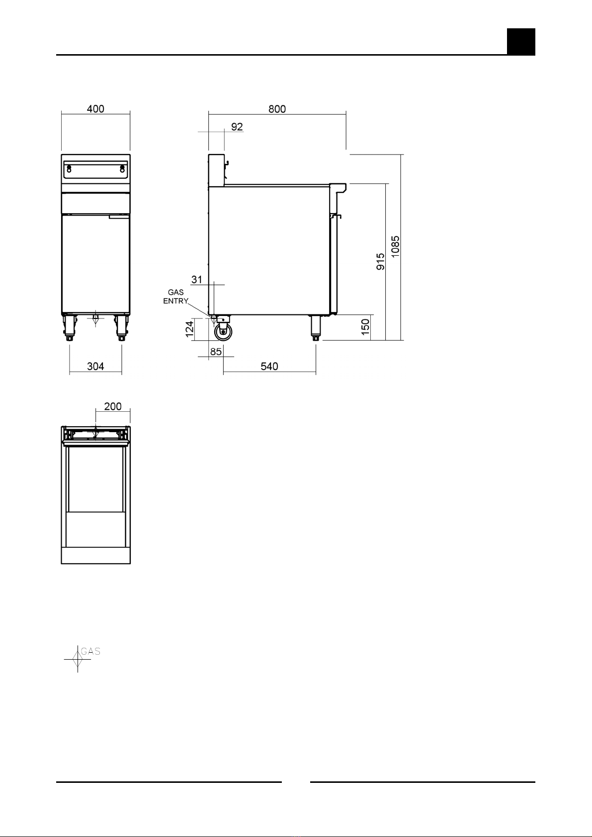
4. Correctly locate the appliance into its final
operating position and using a spirit level, adjust
the legs so that the unit is level and at the
correct height.
5. Connect the gas supply to the appliance.
6. Verify the operating pressure remains correct.
Please note that the outlet pressure is factory set
and is NOT to be adjusted.
7. Check all gas connections for leakages using
soapy water or other gas detecting equipment.
NOTE:
The regulator supplied is convertible between
Natural Gas and LPG, but it’s outlet pressure is fixed
ex-factory and is NOT to be adjusted.
8. Turn ‘OFF’ the mains gas supply and bleed the
gas out of the appliance gas lines.
9. Turn ‘ON’ the gas supply and the appliance.
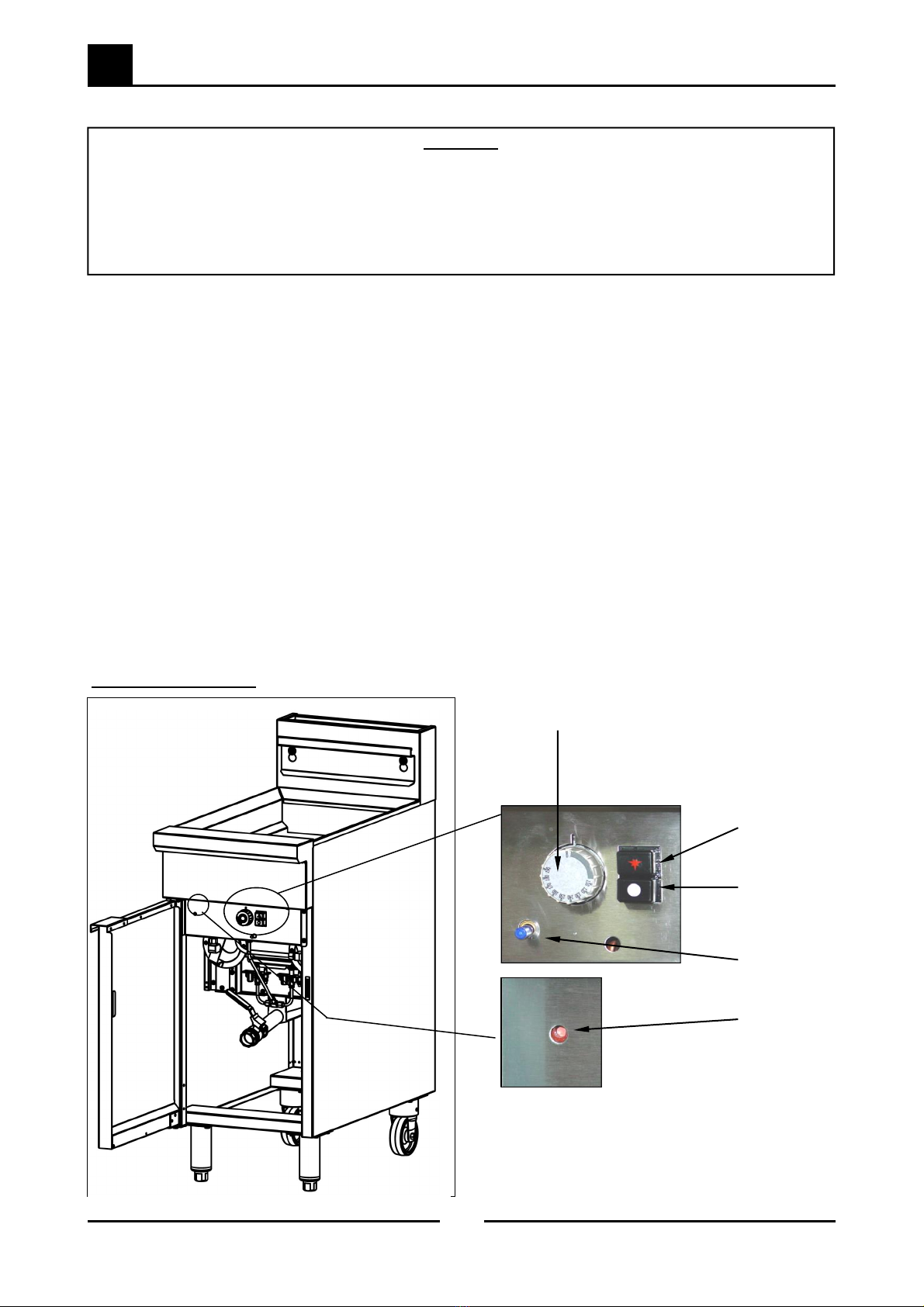
10. Please note that the pilot flame size is factory set
and paint sealed. Check that the pilot covers
the thermocouple. If the pilot needs adjusting,
this should be carried out by an qualified service
agent.
Flexible Hose Connection;
If a Gas Hose assembly is used to connect
this appliance, the hose and all fittings
must have a
minimum ¾” (Natural Gas) or ½” (LPG)
inside bore diameter to ensure gas flow
rate capacity
required by this appliance is achieved.
This must be verified by the operating
pressure testing at the maximum gas sup-
ply demand condition.
The Gas Hose assembly should also be
classified for use in the commercial kitch-
en conditions, the appliance will be used
in.
Recommended Gas Hose Assembly Spec-
ification:
- AS/NZS 1869 Class B or D compliant or
equivalent, that meets the following
requirements:-
Assembly
This model is delivered completely assembled.
Ensure that the legs are securely attached.
NOTE:
This appliance is fitted with adjustable feet to enable
the appliance to be positioned securely and level.
This should be carried out on completion of the gas
connection. Refer to the 'Gas Connection' section.
Gas Connection
NOTE:
ALL GAS FITTING MUST ONLY BE CARRIED OUT BY A
QUALIFIED SERVICE PERSON.
1. COBRA Model Fryers do not require an electrical
connection, they function totally on the gas
supply only.
2. It is essential that the gas supply is correct for the
appliance to be installed and that adequate
supply pressure and volume are available. The
following checks should therefore be made
before installation:-
a. The Gas Type the appliance has been
supplied for is shown on coloured stickers
located above the gas entry point and next
to the rating plate. Check that this is correct
for the gas supply the appliance is being
installed for. The gas conversion procedure is
detailed in the Service Manual.
b. Supply Pressure required for this appliance is
shown in the “Specifications” section of this
manual. Check the gas supply to ensure that
adequate supply pressure exists.
c. Input Rate of this appliance is also stated on
the Rating Plate fitted to the inside of the
access door and in the “Specifications”
section of this manual. The input rate should
be checked against the available gas supply
line capacity. Particular note should be
taken if the appliance is being added to an
existing installation.
NOTE:
It is important that adequately sized piping runs
directly to the connection joint on the appliance,
with as few tees and elbows as possible to give
maximum supply volume.
3. A suitable joining compound which resists the
breakdown action of LPG must be used on eve-
ry gas line connection, unless compression fit-
tings are used.
The connection to the appliance is 3/4” BSP male.
NOTE:
A Manual Isolation Valve must be fitted to the
individual appliance supply line.
WARNING:
DONOT USE ANAKED FLAME TO CHECK FOR GAS LEAKAGES.
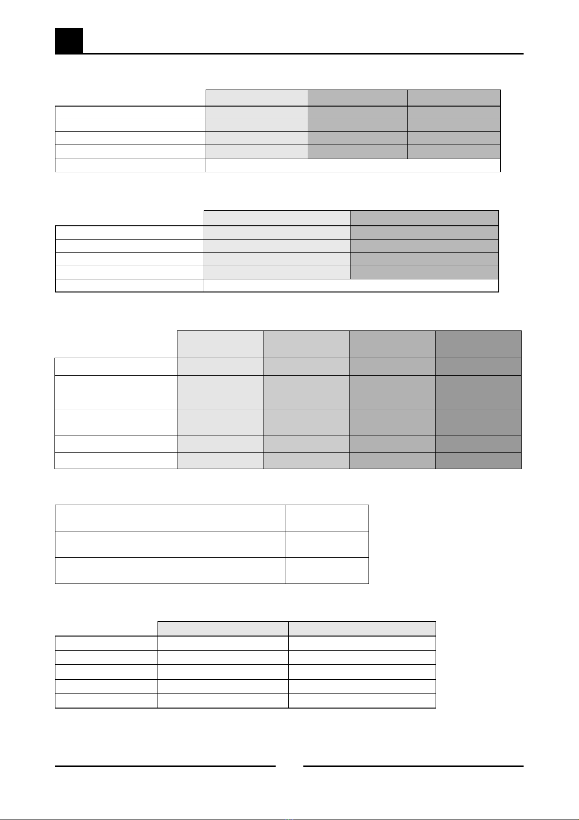
Class
Max Working
Pressure
at 23 ± 2ºC
Working
Temperature
Range
Resistance
to Oil
B 7.0 kPa - 20ºC to +
125ºC
D 2.6 MPa
Oil resistant
lining and
cover.

2
Installation
5
Moffat Cobra Series - CF4 © Moffat Ltd, August 2012
Amendment 4
Commissioning
The following commissioning checks must be
carried out before the fryer is handed over for use,
to ensure that the unit operates correctly and the
operator(s) understand the correct operating
procedure.
1. Before leaving the new installation;
a. Check the following functions in accordance
with the operating instructions specified in
the “Operation” section of this manual.
Light the Pilot Burners.
Light the Main Burners.
Check the Thermostat Operation (refer to
the “Operation” section of this manual).
b. The thermostat operation check should be
carried out by filling the fryer with oil /
shortening to the oil 'FILL LEVEL' mark at the
rear of the tank (refer to 'Filling the Tank' in
the 'Operation Section' of the Manual) and
setting the thermostat to 180°C. Light the
pilot burners and turn on the main burners in
accordance with 'Operation Instructions'
found in this manual.
c. The calibration of the thermostat should be
checked once the oil is up to temperature. If
a discrepancy is found, the thermostat
calibration should be referred to the supplier.
d. Ensure that each operator has been
instructed in the areas of correct lighting,
operation, and shutdown procedures for the
appliance.
2. This manual must be kept by the owner for future
reference and a record of Date of Purchase,
Date of Installation and Serial Number of Unit
recorded and kept with this manual. (These
details can be found on the Rating Plate
attached to the inner R/H side of the front access
door panel.
NOTE:
If for some reason it is not possible to get the
appliance to operate correctly, shut off the gas
supply and contact the supplier of this unit.

3 Operation
6
Moffat Cobra Series - CF4 © Moffat Ltd, August 2012
Amendment 4
Description of Controls
A commercial gas fired Fryer using a fast fry infra
red burner system.
Available in single model type only.
This model is fitted with dual main burners and
pilot burners.
Fitted with single gas controller and additional
flame failure valve to control main burners and
pilots.
Fryers feature an Over Temperature Safety Cut
Out system with Full Flame Failure Safety
Controls.
Snap action thermostat sensitive to changes in
oil temperature.
Open tank design to simplify the cleaning
operation.
Operation Guide
1. COBRA Fryers have been designed to provide
simplicity of operation and 100% safety
protection.
Improper operation is therefore almost
impossible, however bad operation practices can
reduce the oil / shortening life and produce a poor
quality product.
To operate this fryer correctly please read the
‘Installation and Operation’ Manual supplied with
the Fryer.
CF4 Single Tank Controls
C
AUTION
:
This appliance is for professional use and is only to be used by qualified persons.
Only qualified service persons are to carry out installation, servicing or gas conversion
operations.
Components having adjustments protected (e.g. paint sealed) by the manufacturer
should not be adjusted by the user / operator.
Thermostat Control
Knob
'OFF' Button
(Turns 'Off'
Gas Valve
and Pilot).
Pilot Ignition
Button
Flame Failure
Button
Overtemp
Reset Button
Figure 3a

4
Maintenance
7
Moffat Cobra Series - CF4 © Moffat Ltd, August 2012
Amendment 4
COBRA GAS FRYER - MAINTENANCE SCHEDULE
Business Name and Address:
Date: Service Report No:
Phone: Fax:
Serial No:
Clients Order No: Serviceman:
Model: Remarks
1 Inspect exterior condition of the unit.
2 Check working gas pressure is correct to figures shown on rating plate. Pressure _____ kPa.
3 Check pilot flames / correct size.
4 Check that all burner ports light. Clear any blockages, if any.
5a Inspect thermocouples.
5b Replace thermocouples (every 12 months).
6 Check injectors are clean and free from blockages.
7 Check for tightness of gas connections.
8 Check for gas leaks.
9 Check the pilot ignition functions correctly.
10 Check the thermostat calibration.
Service Comments:
Additional work / repairs required:
Customers approval:
Name (print): Title:
Customers signature: Date:
Suggestion: Photocopy this form and keep on file for continued use.
NOTE: For information on cleaning of this appliance, refer to the ‘Installation and Operation’ Manual supplied
with this appliance.

5 Fault Finding
8
Moffat Cobra Series - CF4 © Moffat Ltd, August 2012
Amendment 4
Fault Possible Cause Remedy
Pilot will not light. No gas supply.
Gas pressure too low.
Knob on gas control won’t go
fully in.
Flame failure valve pilot button
will not go fully in.
Blocked pilot injector.
Ensure gas is connected and on
and bottles are not empty.
Check gas supply pressure.
(Refer Specifications Section).
Remove obstruction. Correct
control / wrapper mounting.
Replace gas control valve.
(Refer Section 6.2.8 / 6.2.9).
Replace flame failure valve.
(Refer to Section 6.2.10).
Clean or replace pilot injector.
(Refer Section 6.2.3).
Pilot goes out when knob released. Releasing knob before the
thermocouple heated.
Pilot flame too small.
(Refer Fault: Pilot Flame too Small)
Thermocouple faulty.
(Refer Fault Diagnosis 5.2.1)
Over-temperature thermostat
tripped reset or faulty.
(Refer Fault Diagnosis 5.2.1)
Gas control valve faulty.
Flame failure valve faulty.
Hold control in for longer (10 secs),
see if pilot will stay lit.
Correct fault.
Replace thermocouple.
(Refer Section 6.2.2).
Replace over-temperature
thermostat.
(Refer Section 6.2.5).
Replace gas control magnet.
Replace flame failure magnet.
Pilot flame small. Gas pressure too low.
Pilot adjustment screw out of
adjustment.
Pilot injector restricted.
Check gas supply pressure.
(Refer Specifications Section).
Adjust pilot adjustment screw.
(Refer Section 6.3.1).
Clean pilot injector.
(Refer Section 6.2.3).
Pilot goes out when main burner
comes 'On'.
Incorrect gas pressure.
Faulty gas control.
Check supply / adjust pressure.
(Refer Specifications Section).
Replace gas control valve.
(Refer Section 6.2.10 / 6.2.11).
5.1 Fault Finding Chart
WARNING:
ALL INSTALLATION AND SERVICE REPAIR WORK MUST BE CARRIED OUT BY QUALIFIED PERSONS ONLY.
IMPROPER INSTALLATION, ADJUSTMENT, ALTERATION, SERVICE OR MAINTENANCE CAN CAUSE PROPERTY DAMAGE, INJURY OR DEATH.
READ THE INSTALLATION, OPERATING AND MAINTENANCE INSTRUCTIONS THOROUGHLY BEFORE INSTALLING OR SERVICING THIS
APPLIANCE.

5
Fault Finding
9
Moffat Cobra Series - CF4 © Moffat Ltd, August 2012
Amendment 4
Fault Possible Cause Remedy
Pilot goes out while frying, will not
re-light (Overtemp thermostat has
tripped).
Over-temperature thermostat
faulty (oil below 205ºC / 401ºF).
(Refer Fault Diagnosis 5.2.1).
Thermostat out of calibration (oil
over 205ºC / 401ºF).
Replace over-temperature
thermostat.
(Refer Section 6.2.5).
Recalibrate thermostat.
(Refer Section 6.3.2).
Pilot goes out while frying, can
re-light. (Overtemp thermostat has
not tripped).
Gas supply - incorrect or
fluctuating pressure.
Draught at installation (blowing
pilot out).
Thermocouple faulty.
(Refer Fault Diagnosis 5.2.1).
Over-temp thermostat faulty.
(Refer Fault Diagnosis 5.2.1).
Main gas control valve faulty.
Flame failure valve faulty.
Check supply / adjust pressure.
Shield fryer from excessive breeze.
Replace thermocouple.
(Refer Section 6.2.1 / 6.2.2).
Replace.
(Refer Section 6.2.5).
Replace gas control magnet.
Replace flame failure magnet.
Main burners will not light. Incorrect supply pressure.
Wrong size or blocked injectors.
Small pilot flame.
(Refer Fault: Pilot Flame too Small).
Faulty gas control.
Check supply correct pressure.
Replace / clean injectors.
(Refer Section 6.2.6).
Correct fault.
Replace gas control.
(Refer Sections 6.2.8 / 6.2.9).
Pilot flame yellow / lazy. Gas pressure incorrect.
Restriction in pilot injector or
aeration.
Check gas supply pressure.
(Refer Specifications Section).
Clean or replace as required.
(Refer Section 6.2.3).
Burners do not burn correctly (roar /
light back / incorrect colour).
Incorrect supply pressure.
Pilot too small or too large.
Incorrect injector sizes.
Burner faulty.
Check supply pressure.
Adjust pilot size.
(Refer Section 6.2.3).
Check injector sizes and replace
if necessary.
(Refer Appendix ‘A’, ‘Gas
Specifications’).
Replace burner.
(Refer Section 6.2.7).

5 Fault Finding
10
Moffat Cobra Series - CF4 © Moffat Ltd, August 2012
Amendment 4
Fault Possible Cause Remedy
Set temperature not reached. Gas supply fluctuating.
Thermostat out of calibration.
Placing food into oil too soon.
Too large a load.
Supply correct pressure.
Recalibrate thermostat.
(Refer Section 6.3.2).
Give the fryer more time to come
up to temperature before inserting
food.
Reduced load size will allow the
fryer to recover temperature quick-
er.
Oil too hot. Thermostat out of calibration. Re-calibrate thermostat.
(Refer Section 6.3.2).

5
Fault Finding
11
Moffat Cobra Series - CF4 © Moffat Ltd, August 2012
Amendment 4
To test the thermocouple connected to the gas
control valve. Light the pilot burners, and while still
holding the flame failure button depressed,
measure the voltage between the line to the over-
temp and earth using a multimeter. (See
Figure 5.2.1c below) The reading should be
approximately 30mV.
If the reading is less than 10mV and there is
satisfactory flame impingement on the
thermocouple the thermocouple is faulty - replace
the interrupted thermocouple.
If the voltage is over 10mV then there is a fault with
the flame failure valve electromagnet - replace the
flame failure valve.
With the pilot burners lit and while still holding the
flame failure button depressed, measure the
voltage between the line from the overtemp and to
earth using a multimeter. (See Figure 5.2.1d.).
If the reading is over 5mV, the gas control valve is
faulty - replace the gas control valve.
If the reading is less than 5mV and there is
satisfactory flame impingement on the
thermocouple the overtemp is faulty - replace the
overtemp.
Or there are faulty connections between the
interrupter block and the overtemp - check, clean
and re-tighten all connections and re-test.
5.2 Fault Diagnosis
5.2.1 Pilot Drops Out
Pilot Flame too Small
If the pilot can be lit but the flame is too small to
impinge on the thermocouple, then check the gas
pressure. If the gas pressure is correct, check the
adjustment of pilot flow by adjusting the screw
below the control knob on the gas control. If the
pilot flame is still too small, remove the pilot injector
from the pilot burner and check for correct pilot
injector size and blockage of the pilot injector.
Thermocouple Faulty
Check thermocouple connections are secure and
that the over-temperature lead connection to the
interrupter block on the thermocouple is secure
(loose connections will cause high resistance in the
millivolt circuit and result in pilot outage).
If all connections are satis, light the pilot burners.
Press and hold the ignition button on the control
panel depressed and at the same time hold the
flame failure button depressed. Manually light the
pilot burner until the pilot ignites. Continue holding
the ignition button and the flame failure buttons
depressed until the second pilot cross lights from the
first pilot.
Continue holding the ignition button and flame
failure button depressed for approx. 10 to 15
seconds after the second pilot burner has ignited.
Release the ignition button, both pilot burners
should remain alight.
If the pilot flames don't go out when the flame
failure button is released then release the ignition
button.
If the pilot flames go out when the ignition button is
released, there is a problem with the thermocouple
circuit connected to the main gas control valve.
Figure 5.2.1a.
Pilot Screw
Adjustment
Low Fire
Blanking Screw
Gas Control
Valve
Flame Failure
Button
Overtemp
Cut-Out Ignition Button
'Off' Button
Figure 5.2.1b.
Figure 5.2.1c.
Gas Control
Valve
Overtemp Interrupter
Block
Test between
here and Earth
Figure 5.2.1d.
Interrupter
Block
Test between
here and Earth
Overtemp
Gas Control
Valve
Thermocouple
Thermocouple

5 Fault Finding
12
Moffat Cobra Series - CF4 © Moffat Ltd, August 2012
Amendment 4
Disconnect the connection between the
thermocouple and the flame failure valve and
measure the voltage using a multimeter.
If the voltage is over 10mV then there is a fault with
the flame failure valve electromagnet — replace
the flame failure valve.
If the voltage is under 10mV then the overtemp is
faulty or the pilot is too weak — check the reason
for a weak pilot and rectify, or replace the over-
temp.
Overtemp Tripped
Check the oil temperature with a thermometer.
If the oil temperature has reached over 220°C the
overtemp should have tripped (open circuit), and
cannot be reset until the temperature has dropped
below 192°C.
If the oil temperature is below 180°C and the over-
temp still cannot be reset, the overtemp is faulty.
Overtemp Faulty
To check if the overtemp is faulty, hold 'In' the gas
control ignition button and manually light the pilot
burners (Holding the control button depressed to
keep the pilot alight).
Using a multimeter, measure the voltage from the
gas control side of the thermocouple interrupter
block to earth. If the voltage is under 5mV (and the
thermocouple is generating at least 20mV) then the
overtemp is faulty—replace the overtemp.
If all of the above checks out satis, then check the
gas control valve or thermocouple.
Figure 5.2.1e.
Disconnect here
and Test
Flame Failure
Valve
Thermocouple

6
Service Procedures
13
Moffat Cobra Series - CF4 © Moffat Ltd, August 2012
Amendment 4
Section Page Number
6.1 Access .................................................................................................................................14
6.1.1 Control Panel ...................................................................................................................................14
6.2 Replacement ......................................................................................................................14
6.2.1 Thermocouple (Gas Control) ........................................................................................................14
6.2.2 Thermocouple (Flame Failure Valve) ..........................................................................................15
6.2.3 Pilot Injector......................................................................................................................................15
6.2.4 Pilot Burner ........................................................................................................................................15
6.2.5 Over-Temperature Safety Thermostat .........................................................................................15
6.2.6 Main Burner Injector........................................................................................................................16
6.2.7 Main Burners .....................................................................................................................................16
6.2.8 Gas Valve Removal ........................................................................................................................18
6.2.9 Gas Valve Re-Fitting........................................................................................................................19
6.2.10 Flame Failure Valve.........................................................................................................................20
6.3 Adjustment / Calibration ...................................................................................................21
6.3.1 Pilot Flame Adjustment...................................................................................................................21
6.3.2 Thermostat Calibration...................................................................................................................21
6.3.3 Operating Pressure..........................................................................................................................22
WARNING:
ALL INSTALLATIONAND SERVICE REPAIR WORK MUST BE CARRIED OUT BY QUALIFIED PERSONS ONLY.
ENSURE GAS SUPPLY IS SWITCHED ‘OFF’ BEFORE SERVICING.
ALWAYS CHECK / TEST FOR GAS LEAKS AFTER SERVICE REPAIRS ON THE GAS SYSTEM.

6 Service Procedures
14
Moffat Cobra Series - CF4 © Moffat Ltd, August 2012
Amendment 4
6.1.1 Control Panel
6.1 Access
Figure 6.2.1a.
6.2 Replacement
6.2.1 Thermocouple (Gas Control)
1. Disconnect thermocouple from the rear of the
gas control valve.
2. Unscrew thermocouple securing nut from pilot
burner and remove thermocouple.
3. Unscrew the wires from the thermocouple
interrupter block to the overtemp.
4. Replace thermocouple and reconnect. When
screwing thermocouple back into gas control,
once thread has tightened up tighten another
¼ turn only. Do not over tighten.
1. Remove 2 screws from the underside of the
fascia panel. The panel can now be lifted off
and removed.
2. Remove the 4 screws from either side of the
controller panel. The controller panel can now
be removed.
Facia Screws
Figure 6.1.1.
Figure 6.2.1c.
Thermocouple
Connection
Interrupter
Block
Viewed from below the Valve
Controller Panel
Screws
Thermocouple
Figure 6.2.1b.
Unscrew these
wires

6
Service Procedures
15
Moffat Cobra Series - CF4 © Moffat Ltd, August 2012
Amendment 4
6.2.2 Thermocouple (Flame Failure
Valve)
Figure 6.2.2.
1. Remove the front facia panel. (Refer 6.1.1.).
2. Remove the controller panel. (Refer 6.1.1.).
3. Disconnect thermocouple from the flame
failure valve.
4. Unscrew thermocouple securing nut from the
pilot burner bracket.
5. Replace thermocouple and reconnect.
When screwing the thermocouple back into
gas control, once thread has tightened up
tighten another ¼ turn only. Do not over tight-
en.
1. Drain oil from the fryer.
2. Remove the front facia panel (Refer 6.1.1.).
3. Remove the controller panel. (Refer 6.1.1.).
4. Disconnect overtemp leads (blue) from the
interrupter block on the gas control valve
thermocouple to the overtemp, at the over-
temp connections.
6.2.3 Pilot Injector
1. Disconnect pilot supply tube from pilot burner
and tee by unscrewing nuts and olive.
2. Remove pilot injector, and clean or replace
pilot injector as necessary.
NOTE:
Ensure that the correct size injector is used (Refer
to the Specifications section).
3. Re-assemble in reverse order.
Disconnect
Thermocouple Here
Figure 6.2.5a.
Figure 6.2.3.
Disconnect Pilot
Supply Tube here
1. Disconnect the thermocouple from the pilot
burner bracket.
2. Disconnect pilot supply tube to the pilot burner
at the 'T' Junction and unscrewing the nut and
olive.
3. Remove screw securing the pilot burner brack-
et to front of the fryer, and remove pilot burner
assembly.
4. Replace pilot burner and re-assemble. Ensure
correct pilot injector is re-fitted (Refer to the
Specifications section).
6.2.4 Pilot Burner
Figure 6.2.4.
Disconnect Pilot
Supply Tube here
6.2.5 Over Temperature Safety
Thermostat
Disconnect Overtemp
Leads Here
Pilot Burner Bracket
Securing Screw

6 Service Procedures
16
Moffat Cobra Series - CF4 © Moffat Ltd, August 2012
Amendment 4
5. Remove the overtemp thermostat guard cover
from the bracket in the fryer tank and remove
thermostat.
6. Unscrew and remove the overtemp thermostat
gland nut and remove thermostat from the
fryer tank.
7. Replace and re-assemble in reverse order, use
a suitable thread sealant on the large over-
temp thermostat nut threads (Locktite 567 or
similar). Tighten to 13.5Nm (120lbs/ins).
Overtemp Thermostat
Gland Nut
Figure 6.2.5c.
Figure 6.2.5b.
Overtemp Thermostat
1. Unscrew each injector out of injector mounts.
2. Remove injector, and clean or replace as
necessary. Ensure correct size of injectors are
re-fitted (Refer to the Specifications section).
6.2.6 Main Burner Injector
Figure 6.2.6.
Main Injector
6.2.7 Main Burners
1. Disconnect the pipe from the gas valve to the
main injector.
2. Unscrew the 2 screws securing main injector
bracket to the front of burner and remove
bracket with main injector and gas pipe still
fitted.
3. Slacken gas pipe from flame failure valve to
the pilot injectors by 2 turns.
4. Unscrew 6 screws from pilot mounting panel
and carefully pull panel to one side away from
burner to be replaced, to allow access.
Figure 6.2.7a.
Main Injector
Bracket Screws
Disconnect
Gas Pipe here
Figure 6.2.7b.
Slacken Gas
Pipe 2 turns
Figure 6.2.7c.
Remove 6 Screws
IMPORTANT:
DO NOT OVER-TIGHTEN THERMOSTAT GLAND NUT OR
INTERNAL DAMAGE MAY OCCUR.
IT IS RECOMMENDED THAT A MAXIMUM TORQUE OF
2.2Nm (20lbs/ins) IS APPLIED TO TIGHTEN.
Other manuals for cf4
1
Table of contents
Other Cobra Fryer manuals