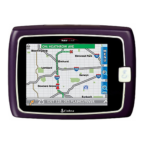
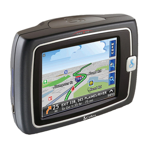
Controls, indicators and System logic 2
Menu button ( MENU )
Goes to the 2Main menu.
Enter button ( ENTER )
Enters the current
selection/entry.
Upbutton (5
)
Scrolls up through list line-by-line, scrolls
upcharacter lists, scrolls up increment
numbers, moves map cursor up and
navigates up in preferences selections.
Down button (6
)
Scrolls down through list line-by-line,
scrolls down character lists, scrolls
down decrement numbers, moves map
cursor down and navigates down in
preferences selections.
Left button (
3
)
Moves to previous character or number,
sequences to previous alphanumeric
character group, moves map cursor left
and navigates left in preferences selections.
Right button (
4
)
Moves to next character or number,
sequences to next alphanumeric character
group, moves map cursor right and
navigates right for preferences selections.
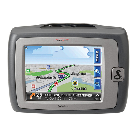
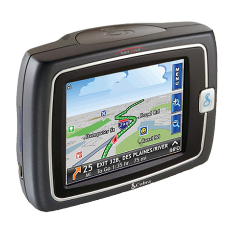
LCD
NAV ONE Signal
Indicator Vehicle Heading
Function Icons USB
Connection
Antenna
Down
Button 1⁄4–20 Tripod
Socket
External Antenna
Connection Port
Up
Button
Right
Button
Enter
Button
Power
On/Off
Button Mounting Bracket
(side view)
Infrared Port and
Light Sensor
Menu
Button
12 Volt
Power
Connection Port
Quick Release
Lever
Left Button
Mounting
Bracket
LCD Brightness
Control (+/-)
LCD Contrast
Control (+/-)
Best signal reception
OK signal reception
Not enough signal reception
Quick Release
Lever (side view)
3
ìNOTE
Pressing the icon on the LCD will not invoke
the function — and may damage the display.
Be sure to press only the function button.
Icon Function Button
ìNOTE
SmartPower is on by default, it shuts down
the system in response to a combination
of three conditions: no vehicle motion or
satellite lock for ten minutes, no button
presses for ten minutes and engine not
running as indicated by supply voltage.
This prevents battery drain while parked.
Installation 4
Installation
The unit can be mounted to the vehicle’s windshield with the included bracket and suction cup, or an
alternative mounting can be devised. See the
Operating Instructions Manual
for more installation information.
THE UNIT MUST BE FIRMLY ATTACHED TO THE VEHICLE. If it is not, it can become a projectile
hazard to vehicle occupants and possibly cause serious injury during a violent maneuver or crash.
Position the unit where it is visible at a
glance but will not obstruct the driver’s
view of the road or interfere with the use
ofvehicle instruments and controls.
Donot put the unit over airbag panels
orwithin airbag deployment envelopes.
The unit should be as close to vertical as possible
and not tilted front-to-back or side-to-side.
View From
the Top
Donot let the
mount block
the view of
the sky.
Position the unit so the antenna can “see”
the sky.
Alternative mounting
recommended for
high-pitched
windshields.
5
Tosecure and connect the NAV ONE:
First, select a suitable location where the unit can be mounted vertically and clean the mounting area.
Then, separate the suction cup and mounting bracket assembly from the unit.
See the Operating Instructions Manual if the vehicle has a metallic coated or
integrally heated windshield or to use the unit indoors to plan a trip.
1.FIRMLY press the suction cup against
the windshield by applying pressure to
the central PRESS button. Be sure the
button is pressed all the way in to make
sure ALL the air is out of the suction cup.
2.While maintaining FIRM pressure
on the button, rotate the lock lever
over the button.
Test suction cup adhesion by pulling on
the bracket. THE ASSEMBLY SHOULD NOT
WIGGLE. If it does, unlock the lever and
repeat steps 1 and 2.
3.Attach the unit to the mounting bracket
bymeans of the quick release feature.
4.Plug the power cord into the unit and
the vehicle’s 12 volt power socket.
Use the quick release lever to temporarily
remove the unit from the mounting bracket
when the vehicle is parked to prevent theft
orheat damage. Be sure to turn off the power
before moving the unit to avoid damage to
the hard drive where the database is stored.
The suction cup portion of the bracket
can be left attached to the windshield
for quick reinstallation.
CAUTION
All air must
be removed.
3
3
3
3
3
3
Basic operation, start-up and Preferences 6
Basic operation and start-up
Be sure to read the IMPORTANT SAFETY INFORMATION on pages 3 and 4 of
the
Operating Instructions Manual
before the first use of the NAVONE system.
Power on/off
After installation is complete and the vehicle is in an open area, turn on the unit (press and hold the POWER button on the side of the unit).
Each time the unit is turned on, a start-up screen appears on the LCD followed by a safety reminder and an opportunity to select a language.
Then, pressing ENTER will bring up either the 2Main menu or the 2Continue route guidance menu. Each time the system is turned off
(press the POWER button again), the system will retain all information to be recalled when it is turned on again.
When the GPS Navigation System is new (or has been idle for more than seven days or has moved more than 500 miles while off),
it can take up to five minutes for the system to lock onto the GPS satellites. After such a start-up, the system should be left turned
on for at least 20 minutes to download GPS satellite data. Having updated satellite data will allow much faster satellite acquisition
and lock — typically less than a minute — when the unit is turned on again.
Preferences
Users can select settings from the
2Preferences menu as shown to the
right. To reach this menu, press the
OPTION function button at the 2Main
menu, then ENTER at the [Preferences]
bar on the 2Option menu. See the
Operating Instructions Manual
for the other
choices listed on the 2Option menu.
ìNOTE
Cobra recommends that
the system be used for
awhile with the default
settings; then users may
make changes. (See
page 20 of the Operating
Instructions Manual
for more about defaults
and choices.)
Preference menu
Options
0(off–no sound)
1–8(softest to loudest)
1– 5 (smallest to largest area)
Heading up or north up
On or off
Auto, day or night
Mile, mile/yd, km or km/m
Onor off
On or off
Preferences
Volume
-012345678+
Zoom Level
-12345+
Map View Heading Up >
Auto Reroute On >
Color Scheme Auto >
Units Mile >
Smart Power On >
Key Click On >
Text and list entries (spell and list modes) 7
Text and list entries (spell and list modes)
The spell and list modes are used to enter information or
choose from lists when selecting destinations, entering data
item names and editing entries. Most times, the system will
default to list mode, but both methods are available by
using the SPELL and LIST function buttons to toggle
between them. Using a combination of the methods
often is the fastest way to make an entry.
Spell mode
Spell mode enables the user to spell out information using the alphanumeric
and numeric-only character loops built into the system as shown at right.
When spelling, scroll5or6to the first character of the entry; then press
the
4
button to advance to the next character(s).
Tomake corrections, press the3
button to erase one character at a time
or press the CLEAR function button to erase the whole entryand start over.
List mode
List mode enables the user to select entries
from data lists in the system database.
When selecting from a list,
the5or6buttons scroll
up or down the list.
Scroll feature in spell mode
List order and characters available
Scroll5or6tomove through
the endless loop of characters
inboth directions.
See the chart below for list order
and characters available.
If the entry is entirely numeric,
such as a zip code, the shorter
numeric list will be presented.
Alphanumeric
0123458
679ABC
DEH
FGIJKLMNO
RPQ
S T U VW X Y &
Z$ ‘ , -
./[]:
The “blank” character shown in these diagrams is the space character.
When scrolling5or6the characters will move in an endless loop.
Numeric
0 1 2 3 4 6789
5
The3
or
4
buttons jump to
the previous or
next alphabetic
group in the list.
Destination selection, Route selection limits and Route calculation 8
Destination selection
Each trip begins with a destination in mind. The 2Main menu provides five
methods of choosing one. After choosing a method, press ENTER to use it.
nA specific street address or an intersection of two streets by spelling or choosing from lists.
nA point of interest, such as a park, restaurant or shopping mall, from extensive lists in the system.
nThe previous origin or any of the last nine destinations entered in the system.
nAny of up to 100 locations that can be saved to the address book.
nMultiple destinations (up to ten) in sequence that are saved as named trips (up to five).
Route selection limits
When ENTER or the GO function button is pressed after selecting a destination,
the system proceeds to the 2Select Route Criteria menu where the user can
define how the system will develop the route to the destination.
Route calculation
When ENTER or the GO function button is pressed at the 2Select Route Criteria
menu, the system develops the route.
Calculation can be stopped with the STOP function to change route criteria or to
cancel it altogether. When the calculation is finished, the system will automatically
proceed to 2Route Guidance at the 2Map screen with the route highlighted in
light green to begin navigation along it. The voice prompt will say, “Please proceed
to the highlighted route.”
Address/intersection 9
Starting with zip code
When selecting an address or intersection, the best starting point is the zip code for the desired destination.
By entering the zip code as the first element of the address, the NAV ONE system will zoom in and look
at only that area. It will always return an associated state and either a single city or a short list to choose
from if more than one city shares the zip code. It allows the quickest destination address selection.
At the 2Address menu, scroll5or6to zip and press ENTER.
Starting with state
If the zip code is not known, the state in which the destination is located must be the first address element
to be entered. This also allows the system to zoom in on a segment of its database for efficient searching.
At the 2Address menu, scroll5or6to [State] and press ENTER.
Completing the address or intersection
After the state has been selected, scroll5or6to the next blank elements — city, street, and number or
cross-street — in turn. Press ENTER and select the element using spell or list modes.
Once the address or intersection is completely filled in, the GO function button will become active. Pressing
ENTER or the GO function button will proceed to the 2Select Route Criteria menu.
Street or intersection
The INTERSECTION function button toggles the system from the 2Address menu to the 2Intersection menu.
The address element entry process is the same for both methods until the last step at which either the street
number or the cross street is entered. It is possible to toggle between these modes after the state, city and
street have been entered. Instructions for the 2Address menu apply to the 2Intersection menu as well.
Clear function
When using the address/intersection method to select a destination, the CLEAR function will clear the
highlighted entry as well as any sub-fields. For instance, clearing the city field will also clear the street
and number or cross-street fields.
