Cobra CX50P3 User manual

DISCLAIMER OF WARRANTY
This motorcycle is sold “as is” with all faults, obvious or not. There are no warranties
expressed or implied, including any warranty of merchantability and warranty of fitness
for any particular purpose.
WARNING
THE COBRA CX50P3 IS A COMPETITION MODEL ONLY AND IS NOT
MANUFACTURED FOR, NOR SHOULD IT BE USED ON PUBLIC STREETS, ROADS
OR HIGHWAYS.
THE USE OF THIS BIKE SHOULD BE LIMITED TO PARTICIPATION IN
SANCTIONED COMPETITION EVENTS UPON A CLOSED COURSE BY A
SUFFICIENTLY SKILLED RIDER AND SHOULD NOT BE USED FOR GENERAL
OFF-ROAD RECREATIONAL RIDING.
IMPROPER USE OF THIS MOTORCYCLE CAN CAUSE INJURY OR DEATH.
THIS BIKE IS INTENDED FOR EXPERIENCED RACERS ONLY AND NOT FOR
BEGINNERS.
IT IS YOUR RESPONSIBILITY AS THE OWNER OF THIS COBRA MOTORCYCLE
OR AS THE PARENT, OR LEGAL GUARDIAN OF THE OPERATOR, TO KEEP THIS
COBRA MOTORCYCLE IN PROPER OPERATING CONDITION.
THIS BIKE WAS DESIGNED FOR RIDERS THAT WEIGH LESS THAN 80 LBS WITH
FULL RIDING GEAR AND SHOULD NOT BE OPERATED BY RIDERS THAT WEIGH
MORE.
BE SURE THAT THE RIDER ALWAYS WEARS ADEQUATE SAFETY GEAR
EVERYTIME HE OR SHE RIDES THEIR COBRA MOTORCYCLE.
IMPORTANT SAFETY NOTICE
Failure to follow WARNING instructions could result in severe injury or death to
the machine operator, a bystander, or a person inspecting or repairing the
machine.
CAUTION:
A CAUTION indicates special precautions that must be taken to avoid damage to
the machine.
NOTE: A NOTE provides key information to make procedures easier or clearer.
MCCL2017.0

2
Table of Contents
General Information..........................................................................................................4
Specifications - General................................................................................................4
Optional Suspension Components................................................................................5
Specifications - Torque Values .....................................................................................5
Break-In Procedure.......................................................................................................6
Starting Procedure........................................................................................................7
Maintenance .....................................................................................................................8
Tips ...............................................................................................................................8
Schedule.......................................................................................................................9
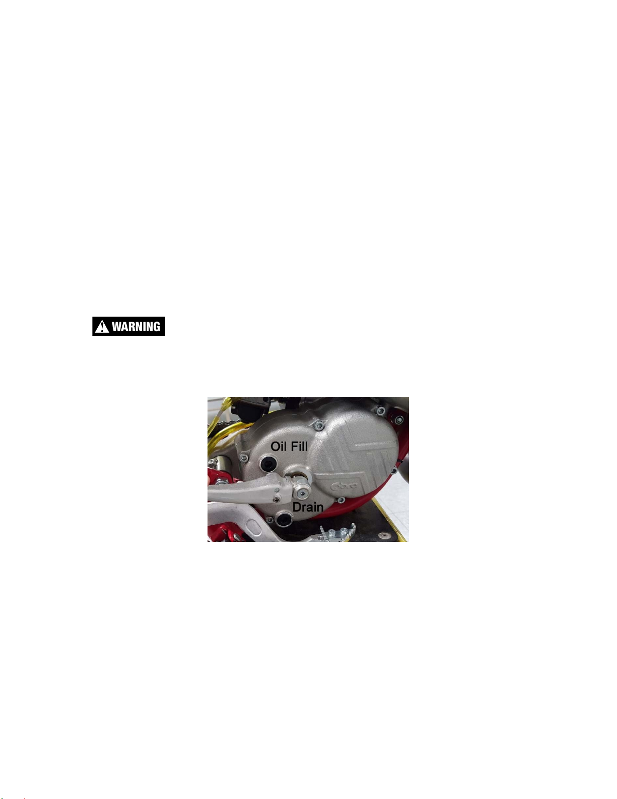
Replacing Transmission / Clutch Lubricant.................................................................10
Proper Chain adjustment ............................................................................................11
Rear Brake Maintenance ............................................................................................11
Brake Bleeding Procedure..........................................................................................12
Air Filter Cleaning........................................................................................................13
Fork Maintenance .......................................................................................................14
Fork Air Bleeding.....................................................................................................15
Fork Oil Replacement .............................................................................................15
Cobra Frictional Drive (V3 CFD).................................................................................16
Parts................................................................................................................................18
Parts – Airbox and Inlet System..................................................................................18
Parts – Bars and Controls...........................................................................................19
Parts - Carburetor .......................................................................................................20
Parts – Coolant System ..............................................................................................21
Parts – Electrical System............................................................................................22
Parts – Engine – Bottom End and Transmission ........................................................24
Parts – Engine Clutch and Kick Lever.........................................................................26
Parts – Engine – Water Pump.....................................................................................28
Parts – Engine – Top End...........................................................................................29
Parts – Exhaust System..............................................................................................30
Parts – Forks & Triple Clamps....................................................................................32
Parts – Forks – Leg Assembly....................................................................................34
Parts – Frame – Mounting Hardware I........................................................................36
Parts – Frame – Mounting Hardware II.......................................................................37
Parts – Front Brakes...................................................................................................38
Parts – Front Wheel....................................................................................................39
Parts – Plastic & Seat .................................................................................................40

3
Parts – Rear Brake......................................................................................................41
Parts – Rear Wheel.....................................................................................................42
Parts – Shock..............................................................................................................43
Parts – Shock - Internal...............................................................................................44
Parts – Swingarm Assembly.......................................................................................45
Service............................................................................................................................46
Engine Service............................................................................................................46
Base Gasket Selection............................................................................................47
CFD Adjustment......................................................................................................48
Engine Removal......................................................................................................49
Complete Engine Disassembly Procedure..............................................................50
Top End Disassembly Procedure............................................................................50
Splitting the Cases..................................................................................................51
Engine assembly.....................................................................................................52
Clutch..........................................................................................................................53
Clutch Assembly .....................................................................................................57
Ignition.........................................................................................................................58
Cooling System...........................................................................................................59
Fuel & Air System .......................................................................................................61
Carburetor...............................................................................................................61
Reeds......................................................................................................................63
Exhaust.......................................................................................................................63
Rear wheel pullers ..................................................................................................63
Brakes.........................................................................................................................64
Rear Shock .................................................................................................................66
Tuning.............................................................................................................................67
Suspension .................................................................................................................71
Adjustment ..............................................................................................................71
Front Fork Operation...............................................................................................72
Carburetion .................................................................................................................72
Troubleshooting..............................................................................................................75

4
General Information
Specifications - General
Items CX50 P3
Dimensions
Wheelbase 35.75” (908mm)
Wheel size 10” (254mm)
Seat height 22” (558 mm)
Engine
Type 2-stroke, single cylinder, reed valve
Cooling system Liquid-cooled
Coolant Moto Chill
Displacement 49.8 cc
Bore and stroke 39 mm x 41.7 mm
Ignition system Electronic, analogic advance
Spark plug Autolite - XS61 & 4261
Gap 0.023” – 0.025” (0.58 – 0.64 mm)
Ignition timing 0.040” (1.0 mm) Before Top Dead Center (BTDC)
Fuel type High octane pump gasoline
Premix Oil type Bel-Ray H1-R
Premix oil ratio after break-in 40:1 to 50:1
Carburetion 12 mm Dell’Orto
Slow (Pilot) Jet / Main Jet 55 / 92
Needle - position W7-2
Slide #50
Float Height 16mm + 0.5mm (0.63” + 0.020”)
Transmission
Speed / Clutch Single / Cobra 3 shoe
Final drive ratio 14/37 T
Chain 420
Transmission / clutch oil type Cobra Venom 3 Shoe Clutch Milk
Quantity 300 ml (10oz)
Chassis
Front tire 2.75 (80/100) – 10"
Pressure 15 psi minimum
Rear tire 2.75 (80/100) – 10"
Pressure 15 psi min. (20 psi for hard pack or rocky conditions)
Front fork CARD 32mm USD Fully Adjustable w/ Smart Leg
Fork oil type 2.5wt Bel-Ray Fork Oil
Fork oil amount 145 ml
Std settings
Rear Shock (std settings) Smart leg: 3 out,Compression and rebound 1 1/2 out
Compression Low 7, High 7, No Rebound Adj.

5
Optional Suspension Components
Weight of Rider (lb) Fork Spring Shock Spring
Less than 38 (light) KCCJ3218
(
18 lb/in
,
3.15 N/mm
)
SCMUOH04 (275 lb/in) red
38 – 45 (std) KCCJ3221
(
21 lb/in
,
3.70 N/mm
)
SCMUOH05 (285 lb/in)
y
ellow
46 to 55 (stiff) KCCJ3225
(
25 lb/in
,
4.40 N/mm
)
SCMUOH06 (295 lb/in)
white
Specifications - Torque Values
Fastener Torque Value
Loctite
TM
Size & Remarks
ft-lb in-lb Nm
Cylinder head nuts 9 110 12 M6 X 1.0
Cylinder nuts 22 265 3.0 M8 x 1.25**
Crankcase bolts 8.8 105 12 M6 x 1.0
Spark plug (SP) (SP) (SP) M14 x 1.25
Stator bolts 2.1 25 2.8 243 M5 X 0.8
Stator cover bolts 1.7 20 2.3 M4 X 0.75
Clutch cover bolts 5.8 70 7.9 M6 X 1.0
Clutch nut 40 480 54 263 10 x 1.25
Clutch bolts 12 144 16 263 M6 x 1.0
Engine mount bolts 22 265 30 M8 X 1.25
Swingarm pivot 21 250 28 M14 X 2.0
Shock bolt 35 420 47 243 M10 x 1.5
Triple clamp (top) 12 144 16 M8 x 1.25
Triple clamp (bottom) 6 72 8 M6 x 1.0
Water pump impeller 3.6 44 5 243 M5 x 0.8
Intake manifold bolts 4.6 55 6.2 M6 X 1.0
Ignition rotor nut 33 400 45 243 M10 x 1.25
Rear brake rotor bolts 9 108 12 243 M6 x 1.0
Rear sprocket bolts 16 195 22 243 M7 X 1.0
Axle nuts 25 300 34 M12 X 1.25
** Use a ‘crows foot’ attachment oriented 90° to the torque wrench
(SP) To apply the proper torque to the spark plug when inserting, first screw the
spark plug in until the metal gasket ring causes resistance and then turn another
¼ turn.

6
Break-In Procedure
Your Cobra CX50 P3 is a close-tolerance high performance machine and break-
in time is very important for maximum life and performance. The CX50 P3 can be
ridden hard after the first ½ hour break-in time.
Cobra recommends Bel-Ray H1-R premix oil with high octane
pump gas mixed at 40:1 (150 ml oil to 2 gallons of gas). Other
brands of oil should be mixed at 32:1 for break-in.
CAUTION:
Failure to use proper fuel, oil, or fuel/oil mixture may result in premature engine
wear or damage to the machine.
Adhering to the following break-in schedule will result in long lasting high
performance machine.
Start bike on stand
First 5 minute period, operate the bike on the stand with a combination of idle
and high RPM operation. (avoid prolonged high RPM but spin the rear
wheel good at least once or twice per minute)
Allow bike to cool
Ride for 15 minutes maximum (avoid prolonged high RPM operation and
avoid abusing the clutch with throttle blipping.
Allow bike to cool and inspect bike for loose fasteners.
Avoid prolonged operation at Wide Open Throttle for the next half hour.
After 1 hour of operation
oCheck for loose bolts and nuts.
oClean the carburetor bowl.
oChange the transmission / clutch lubricant.
Check CFD torque and adjust as necessary
After 8 hours of operation
oChange the fork oil.
oHave a Certified Cobra Mechanic or suspension specialist change the
shock oil.
Your bike is now ready for the highest level of competition!
NOTE: During break-in the bike will likely lose some engine coolant through the
radiator overflow hose. Losing up to 4 oz (120 ml) is normal. Proper coolant level
will cover the top of the radiator cores. Removing the radiator cap and looking
inside is the only way to check the coolant level.
Never remove the radiator cap of a machine that has a warm
engine. Burning and scalding could occur.

7
Starting Procedure
Before starting the machine inspect the following:
Tire pressure
Chain tension
Coolant level
Proper wear on chain rollers and sliders
Handlebar tightness
Throttle assembly movement/cable adjustment
Air Filter
Check for loose nuts and bolts
Turn the fuel on by rotating the fuel petcock knob to the vertically downward
position (reserve position is horizontally forward)
NOTE: For best results from your Cobra Motorcycle use only the recommended
fuel. Testing has shown that most ‘race’ fuels actually degrade performance.
Always wear a helmet and other protective riding gear.
When your pre-ride inspection is complete the bike may be started. For a cold
engine follow this procedure.
1. Place the motorcycle on a stand of sufficient strength that positions the
motorcycle in a level upright position with the rear wheel off the ground.
2. Pull up the choke knob and turn it to lock it.
3. Kick start the engine.
4. Rev the engine in short spurts, turning the throttle no more than 1/4 open
until the engine will run without the choke.
5. Verify a functional engine shut-off switch by shutting off the engine.
6. Restart the engine and proceed with riding when the engine is sufficiently
warm (i.e. the side of the cylinder is warm to touch).
CAUTION:
Never rev an engine full throttle until the engine is at operating temperature.
This is a high performance race motorcycle. Too much application of throttle will
likely land your little racer on his or her arse. Fenders can be replaced but
bruised egos and other body parts take longer.
CAUTION: Cobra recommends that you tell your child to take it easy the first
couple of minutes in practice until the engine comes up to full operating
temperature.
CAUTION: Make sure your riders’ foot is not resting on the foot brake while they
are riding
.

8
Maintenance
A properly maintained machine is safer, faster, and more fun to ride. It is
important that you adhere to this maintenance schedule so as to promote the
longevity of your Cobra Motorcycle
Tips
1. Recommended lubricants:
a. Cobra Clutch Milk is by far the best auto clutch lubricant. It is a
full synthetic lubricant that has been specifically formulated for
Cobra’s auto clutch and has;
Exceptional film strength over petroleum based oils or
synthetic blends.
Extreme temperature tolerance.
NO frictional modifiers.
Dispersant package to keep clutch fibers in suspension so
they can be flushed out when the oil is changed.
Extremely low viscosity for minimal drag and ‘windage’.
b. Bel-Ray H1-R oil is the recommended premix oil because:
Its Ester base leaves a film on all parts at all times. No metal
to metal startups or corrosion potential.
Exception film strength over petroleum based oils or other
synthetic blends.
Easily atomizes and burns completely.
Does not fall out of suspension from premix in cold weather.
Produces virtually no coking deposits, leaving pistons, rings
and heads extremely clean with minimal pipe ‘spooge’.
2. Filling your transmission with more than 8.0 oz (235 cc) of lubricant will help
to transfer heat from the clutch. Filling with more than 12 oz (295 cc) will
degrade performance.
3. The cylinder base gasket has been ‘fitted’ for your engine. The code
number stamped into the engine cases will guide you to what thickness
base gasket is required during a common top end service. See the service
section of this manual to correspond a code number with a base gasket part
number.
4. Evaluate the bikes jetting only after it has been warmed up to race
temperatures.
5. New chains will stretch on first use. Never install a new chain prior to a
race. Always ‘break’ them in during practice.
6. Your Cobra Motorcycle has a 10 digit VIN (Vehicle Identification Number).
The first three digits indicate the model while the sixth and seventh
indicates the model year.
a. Example, CP3xx17xxx is a 2017 CX50 P3.
7. Because of the amount of heat generated by the clutch and engine during
extended periods of riding, it is advisable to remove the ignition cover
afterward to allow the ignition to cool off. The heat transfers through the

9
cases and can damage the stator as it cools off because of lack of airflow
around the stator.
8. If you ever need to weld anything on the bike, disconnect the spark plug
cap, unplug the ignition, disconnect the kill switch, scrape the paint bare
near the area to be welded and put the ground clamp as close to the area
to be welded as possible.
Be sure the fuel tank and carburetor have been removed and safely located
away from the welding process.
9. The frame is 4130 Chrome Moly and it is important to weld it with the proper
rod and heat settings set as light as possible. Cobra recommends replacing
the frame with a new one if the old one becomes damaged. Use ER70S6
filler if welding on the frame.
10. If your kick-starter lever does not return properly, first try loosening the six
kick/clutch cover screws ½ turn. Hold the kick lever ½ way down while
retightening the six screws starting for the center and working out
11. Inspect CFD slip torque after the 2
nd
ride and then again after the 6
th
ride.
After this follow the recommended schedule below.
12. Check proper clutch engagement before and after each ride. If the clutch is
engaging properly DO NOT feel the need to take the clutch apart to;
measure the spring stack, clean the stack, replace the springs, etc... Cobra
has worked very hard to make a clutch that is low maintenance and so only
take it apart if it NEEDS to be maintained.
Schedule
Prior to each ride
oCheck that the air filter is cleaned and oiled.
oInsure the smooth operation of the throttle cable (throttle soundly ‘clacks’
shut).
oCheck for frayed strands of the throttle cable inside the throttle housing.
oCheck for adequate tire pressure.
oCheck all nuts and bolts for proper torque.
oSpray all moving parts with WD40 or other light oil.
oCheck drive chain for
Proper tension.
Adequate lubrication.
oInsure that the ignition stator and rotor are clean and dry.
oCheck the frame for cracks in the metal or cracks in the paint that might
Indicate that the metal has been stressed beyond its safe limits.
oCheck the rims for signs of stress, like cracks around the rim, spokes
and hub.
oEqualize the pressure in the forks with atmosphere.
Every 2 hours of operation
oReplace the transmission oil.
oCheck the CFD torque

10
Every 10 hours of operation
oReplace the fork oil.
oHave the shock oil replaced by a Certified Cobra Mechanic.
Replacing Transmission / Clutch Lubricant
Tools needed:
5mm allen wrench
Minimum of 300 ml (10 oz) Cobra Venom 3 Shoe Clutch Milk (Part
#MCMUGF32).
Procedure:
1. Begin this procedure with a bike that has been ridden more than 5 minutes
but less than 10 minutes. It is desired to have the engine warm enough so
that the oil is ‘runny’ but not so hot that there is risk of being burned by the
engine or the oil.
Hot oil and hot components on the motorcycle may cause burns.
2. Remove the oil drain plug located on the right side of the engine, on the
clutch cover, near the brake lever (figure 1).
3. After it has drained, reinstall the plug, being sure that the gasket is in place.
4. Reapply oil from oil fill plug 300 cc (10 oz) Cobra Venom 3 Shoe Clutch Milk
thru the oil fill plug.
NOTE: Putting additional oil, up to 350 ml (12 oz), can help clutch life. More than
350 ml (12 oz) will degrade engine performance.
NOTE: It can be helpful to lean the bike over on its left side to add oil to the bike.
5. Reapply the oil fill plug, hand tight, being sure the gasket is in place.
Figure 1

11
CAUTION:
Cobra has spent considerable time and money developing the proper lubrication
to handle the harsh environment of the automatic clutch and transmission of this
motorcycle. Cobra’s specially developed Cobra Venom 3 Shoe Clutch Milk
(Part
#MCMUGF32) was formulated to provide superior lubrication and cooling
capability over extended periods of time and is the recommended lubricant for
your Cobra motorcycle.
Proper Chain adjustment
Tools required for chain adjustment
19 mm wrench or socket
13 mm wrench or socket
1. Make sure that the rear wheel is aligned
properly.
2.
A properly adjusted chain will have
50mm (2”) free movement behind the
chain block with no load on the bike.
(figure 2)
3.
Sit on the bike and verify that the chain has a
minimum of 12mm (1/2”) free movement when the
chain is at its tightest point.
4. If the chain requires adjusting, loosen the axle
with a 19 mm wrench and tighten the chain by
rotating the adjustor bolts clockwise (CW) or
loosen the chain by rotating the adjustor bolts
(CCW).
5. Retighten the axel bolt to 25 ft-lb (34 Nm).
6. Retighten the adjustor bolt
Rear Brake Maintenance
CAUTION:
Too little brake pedal free-play will allow the brake pads to drag causing the pads
to wear prematurely and possible engine component failures. Too much free-play
will not allow the rider to apply the brakes quickly.
1. Set pedal height/position first, then
2. Set pedal free play.
Brake pedal height can be adjusted with the bolt and nut located under the rear
of the brake pedal. The free-play is adjusted with the adjustable plunger on the
end of the brake pedal.
Fi
g
ure 2

12
CAUTION:
Use only DOT 4 brake fluid
Setting rear brake pedal position (see figure 2b):
1. Loosen the lock nut (10mm wrench).
2. Adjust the brake lever stop (10mm wrench) so that the lever is comfortably
reachable in both:
a. Standing riding
position, and
b. Sitting riding position.
3. Tighten the lock nut (10 mm
wrench).
CAUTION:
Adequate pedal free play is required
so that the brake pads do not drag
on the rotor. 1” MINIMUM.
Make sure that the free play locking
clip is installed such that one must
push forward, toward the front of the
bike, to remove. Otherwise the clip is
apt to come undone while riding.
To adjust (see figure 2b):
1. Loosen the lock nut (10mm).
2. Undo the free play locking clip from around the brake adjustor (plunger),
with your hand by pushing it forward.
3. Slide the pin of the locking free play locking clip from the brake lever
4. Adjust as needed by rotating the clevis on the end of the adjustor
(plunger).
NOTE: Turning the clevis Clockwise will lengthen the adjustor (plunger),
removing free play from the system, and turning the clevis Counter-Clockwise will
shorten the adjustor (plunger) adding free play to the system.
Brake Bleeding Procedure
Tools Required:
Front: T10 Torx bit/driver, Cobra bleed kit (BCKG0031)
Rear: 3mm hex key (Allen wrench, T10 Torx bit/driver, Cobra bleed
kit(BCKG0031)
Procedure:
Remove the brake fluid reservoir cover.
Figure 2b

13
Fill the syringe half full with brake fluid.
Remove the brake caliper bleed screw.
Attach the syringe to the brake caliper bleed access. Keep the syringe
oriented as not to allow air from the syringe into the system.
Using the syringe pull fluid through the system. Use caution not to let the
fluid in the reservoir to become low and introduce air into the system.
Using the syringe push fluid back into the system until the reservoir is full.
Repeat these actions of pulling and pushing fluid through the system a few
times.
With the reservoir full, engage the brake lever/pedal and hold it there as if
engaging the brakes.
While doing this pull on the plunger of the syringe. Doing this will cause a
vacuum in the system. The vacuum will swell the air bubbles which assist
in them moving throughout the system.
Continue pulling a vacuum and release the brake lever/pedal (careful not
to allow the reservoir to become empty).
Once again engage the brakes while continuing to pull a vacuum.
When the reservoir is almost empty stop and push fluid back into the
system.
Repeat these steps with the vacuum until no more air bubbles can be
removed from the system.
Remove the syringe. Be sure to keep the caliper below the level of the
reservoir to allow the fluid to run out of the caliper and not allowing air into
the system.
Reinstall the bleed screw, being sure that the ring is in place.
Fill the reservoir with fluid (the fluid should be full enough that the fluid
spills out when placing the lid on) and replace the cover.
Air Filter Cleaning
Tools recommended for air filter maintenance:
#2 Phillips head screwdriver
4 mm Allen wrench
Foam filter oil

14
Procedure
1. Removed the seat with a 4 mm Allen wrench.
2. Remove the filter/air inlet boot from the back of the carburetor with a Phillips
screwdriver
3. Pull the filter / boot assembly out the top of the air box.
4. Clean the filter in a nonflammable solvent to remove the filter oil.
Do not clean the air filter with gasoline or other highly volatile petroleum product.
Diesel fuel or kerosene would be preferred but caution should still be taken. Hot
soapy water works well.
5. Clean the filter in hot soapy water to remove all dirt particles.
6. Allow it to dry thoroughly.
7. Saturate with filter oil and remove excess.
NOTE: The Cobra is equipped with a special designed Air box. It is very
important to keep the air filter clean and properly oiled with high quality water-
resistant foam filter oil. It’s very important to oil your filter consistently each time
because varied amounts of oil will change your carburetor jetting.
8. Reinstall the filter / boot assembly making sure the letters “CM” are visible
between the carburetor and air box (figure 4).
NOTE: Make sure you change or clean your filter after each moto. We
recommend carrying multiple filters in your toolbox, one for each practice session
and moto.
Fork Maintenance
Cobra strongly recommends that a professional service technician conduct all
internal maintenance other than changing springs and oil. This will help to ensure
safe and consistent operation.
For routine maintenance, the chart below provides suggested service intervals
for common procedures:
Figure 4

15
Each Ride 10 hours 20 hours As Needed
Bleed excess air X
Change Oil X
Change
Seal/Swiper X
Change Bushings X
Fork Air Bleeding
Tools required
3mm hex key (Allen wrench)
During normal operation, both fork legs will build up air pressure. This pressure
acts as an additional spring so it must be bled on a regular basis to maintain
consistent suspension operation. Before each ride, loosen the socket head cap
screw located at the front of each fork cap far enough so that any excess
pressure in the leg is relieved. After excess air is bled off, retighten the screw to 5
in-lb. Be careful not to lose or damage the sealing ring that is located under the
head of each bleed screw.
Fork Oil Replacement
Tools required
32mm Fork Cap Tool (MCMUTL32)
19mm wrench or socket
4 & 5 mm hex key (Allen wrench)
9/16 wrench
Mallet
2.5 wt. Bel-Ray fork oil
Disassembly procedure
1. Remove the front wheel (19 mm wrench).
2. Remove the brake caliper from the fork leg (4 mm hex key).
3. Loosen the fork caps (32mm fork cap tool).
4. Remove the fork legs from the triple clamps (5 mm hex key).
5. One leg at a time
a. Remove the fork cap from the fork tube.
b. Pull the fork spring down to gain access to the fork cap jam nut and
secure it with a 9/16 wrench.
c. Holding in one hand the 9/16 wrench use the fork cap wrench to
unscrew the fork cap from the damper rod.
d. Remove the fork spring pad, and fork spring.
e. Inside the damper rod, the rebound adjustment screw pin is resting
and will fall out of the damper rod when the fork is inverted. Try to
catch it before it falls into your oil bucket.

16
f. Invert the fork and allow the oil to drain completely. Working the
damper rod up and down will speed up the draining process.
Assembly procedure
1. Fill the fork with 140ml of fork oil.
2. Work the damper rod up and down to allow the fork cartridge to fill with oil.
3. Install the rebound adjustment screw pin into the damper rod.
4. Install the fork spring and spring pad.
5. Extend the damper rod completely and Compress the fork spring enough to
begin threading the fork cap back onto the damper rod.
6. Make sure that the fork cap threads onto the damper rod completely before it
makes contact with the jamnut.
7. Tighten the jamnut.
8. Tighten the fork cap to the fork leg outer
9. Pump the fork leg several times to verify that it operates smoothly.
10.Install each leg back into the triple clamp. Torque each pinch bolt to 8N-m (6
ft-lb) making sure both legs are set to the same height in the clamps.
11.Reinstall the brake caliper.
12.Reinstall the front wheel (25 ft-lb, 34 Nm).
Cobra Frictional Drive (V3 CFD)
The Cobra Frictional Drive (CFD) is essentially an adjustable slip clutch that
dissipates torque spikes transmitted from the rear wheel to the rest of the drive
line and engine. Instead of these torque spikes potentially damaging internal
components, the CFD allows the transmission to slip with respect to the engine.
For this to occur, the CFD must
function properly by ‘slipping’ above
a minimum torque value.
The safe minimum slip torque of the
CFD should be checked every 2
hours of operation, after break-in.
The slip torque value should be
above 80 ft-lb (108 Nm) measured at
the sprocket with the following
process.
To properly measure the minimum
torque at which the CFD (Cobra Frictional Drive) slips
1. Remove the oil fill plug and install the check tool/pin MCMUTL40.
2. Make sure that it is threaded in completely until it bottoms out.
3. Install the Sprocket Socket CFD torque checking tool (MCMUTL15) on the
output shaft protruding through the sprocket.

17
CAUTION
It may be necessary to remove the ECKGSR03
sprocket clip, or the sprocket entirely, to ensure good
engagement between the tool and the shaft
4. Verify with a torque wrench applied to the
Sprocket Socket that the V3 CFD does not
slip below 108 Nm (80 ft-lb) in either direction.
5. If there is slippage below 108 Nm (80 ft-lb)
remove the cotter pin and tighten the castle
nut on the CFD one more position (it is a left
hand thread nut so you must turn it counter
clockwise)
NOTE: This V3 CFD torque checking method is
possible do to with the chain on. Just put the bike on
a stand so that the rear wheel can turn freely.
NOTE: The CFD hubs can be removed with the
universal puller (MCMUTL70).
If it slips below the value, the CFD must be readjusted as per described in the
service section of this manual.
NOTE: If the bike makes a whir, whir, whir, sound coming from the clutch side
engine cover it is very probable that the CFD has slipped enough that the brass
bushing has worn sufficiently to let the gear operate off center. Time to install a
CFD refresh kit (EKMU0033).

18
Parts
Parts – Airbox and Inlet System
Airbox and Inlet System
REF # PART # DESCRIPTION
1 ZCCS0001 GASKET
–
REED
TO
CYLINDER
2 ECMU0246 REED
CAGE
ASSEMBLY
WITH
REEDS
VFORCE
3 RCCS0002 INLET
MANIFOLD
4 HCWF0601 6mm
FLAT
WASHER
5 HCBC0603 M6X30mm SOCKET HEAD CAP SCREW
6 MCKGHO04 HOSE
CLAMP
–
CARBURETOR
TO
MANIFOLD
7 RCCL0001 CARBURETOR
12mm – DELLORTO – 2016P3
8 RCCM1301 VELOCITY
STACK
9 MCKGHO01 HOSE
CLAMP
–
AIR
BOOT
TO
CARBURETOR
10 RCCJ0004 AIR
FILTER
WITH
BOOT
11 RCMU0405 AIR
BOX
–
P3
12 HCBB0612 M6X12mm
BUTTON
HEAD
BOLT
(2
REQ’D)
13 RCMU1407 BRACKET
–
MUD
FLAP
14 TCMU0408 MUD
FLAP
–
P3
15 ECCS0030 REEDS
REPLACEMENT
KIT
16 FCMU0026 FUEL
LINE
5”
(NOT
SHOWN)
17 MCMUCL04 HOSE
CLAMPS
–
FUEL
LINE
(NOT
SHOWN)
18 RCMU0022 VENT
HOSE
(NOT
SHOWN)

19
Parts – Bars and Controls
Bars and Controls
REF # PART # DESCRIPTION
1 FAMU0017 HANDLEBAS
–
PRO
TAPER
MICROBARS
–
COBRA
JR/P3
2 TCMU0021 GRIPS
(SET
OF
TWO)
–
MICROGRIPS
–
RED
/
GRAY
FEW
3 FAMU0016 THROTTLE
ASSEMBLY
–
PRO
TAPER
COBRA
3A FAMU0015 TUBE
ASSEMBLY
–
THROTTLE
–
2
PIECE
PRO
TAPER
MICRO
3B HCBC0525 M5
X
25
SHCS
–
THROTTLE
ASSEMBLY
3C FCMU0041 STOP
RING
–
MICRO
BAR
THROTTLE
4 FCPW0004 CABLE
COVER
5 FCMU0021 THROTTLE
COVER
6 FCMU0019 THROTTLE
CABLE
6A HCNJ0801 NUT
–
8MM
JAM
7 BAKG0003 BRAKE
ASSEMBLY
FRONT
8 FCMU0033 KILL
SWITCH
ASSEMBLY
9 HCBC0806 M8X30mm SOCKET HEAD CAP SCREW (4 REQ’D)
10 HCBC1001 M10X45mm SOCKET HEAD CAP SCREW (2 REQ’D)
11 TKMU0404BLK BAR
MOUNT
KIT,
SHORT
(1
REQ’D)
STANDARD
11A TKMU0403 BAR
MOUNT
KIT,
TALL
(1
REQ’D)
12 HCNL1001 M10 LOCK NUT
ACCESSORY BCKG0023 ALLOY BRAKE LEVER W/BALL
ACCESSORY BCKG0024 BRAKE PERCH ASSY W/LEVER & BALL
ACCESSORY MCMUAM11 GRIP DONUT – PAIR – PRO TAPER MICRO BAR

20
Parts - Carburetor
48 RCMU0048 88 RCMU0088 94 RCMU0094
50 RCMU0050 89 RCMU0089 95 RCMU0095
52 RCMU0052 90 RCMU0090 96 RCMU0096
55 RCMU0055 91 RCMU0091 97 RCMU0097
60 RCMU0060 92 RCMU0092 98 RCMU0098
65 RCMU0065 93 RCMU0093
PILOT JET MAIN JET*
*Larger and Smaller sizes are available upon request
Carburetor
REF. # PART # DESCRIPTION
1RACP0012 CARBURETOR
3 RCMU0003 CABLE ADJUSTOR
4 RCCM0312 RESTRICTOR - 12MM CARB
5 RCMU0046 TOP CARB THREAD ON
6 RCMU0102 RUBBER CABLE CAP SEAL
7 RCMU0004L SLIDE SPRING - LIGHT
8 RCMU0028 NEEDLE RETAINER PLATE
9 RCMU0007 NEEDLE CLIP
10 RCMU0305 SLIDE - #40
11 RCMU0601 NEEDLE – W7
12 RCMU0204 CHOKE ASSEMBLY
12A RCMU0209 O-RING CHOKE ASSEMBLY
13 RCMU0009 FUEL MIXTURE SCREW #16
14 RCMU0011 IDLE ADJUSTMENT SCREW #18
15 RCMU0201 SCREW – FLOAT BOWL
20 RCMU00xx PILOT JET, xx denotes size
22 RCMU0262 ATOMIZER 2.62 AU STANDARD*
23 RCMU0107 FLOAT NEEDLE
24 RCMU0012 DIFFUSER #20
25 RCMU0016 FLOAT RETAINER PIN
26 RCMU0301 FLOAT #7
27 RCMU0103 FLOAT BOWL GASKET
28 RCMU0043 FLOAT BOWL W/ THREADED HOLE
29 RCMU00xx MAIN JET, xx denotes size
30 RCMU0044 MAIN JET EXTENSION
31 RCMU0039 FLOAT BOWL PLUG
32 ZCMU0037 BOWL PLUG GASKET
NOT SHOWN
RCCM1301 VELOCITY STACK
NOT SHOWN
RCCS0006 FUEL
LINE,
5”
NOT SHOWN
MCMUCL04 HOSE
CLAMPS
–
FUEL
LINE
NOT SHOWN
RCMU0020 ELBOW - CARB VENT
NOT SHOWN
RAMU0001 CANNULUS - Y STYLE CARB VENTS
ACCESSORY
RCMU0031 SLIDE - #30
ACCESSORY
RCMU0250 SLIDE - #50
ACCESSORY
ECKG0160 SLIDE - #60
ACCESSORY
RCMU0026 NEEDLE - W4
ACCESSORY
RCMU0602 NEEDLE - W16
*Different sizes are available upon request
Table of contents
Other Cobra Motorcycle manuals

Cobra
Cobra 2004 cm50 User manual

Cobra
Cobra 2010 CX65 User manual

Cobra
Cobra King 2003 Application guide

Cobra
Cobra CX50 2014 5R King User manual

Cobra
Cobra 2005 cm50 User manual

Cobra
Cobra 2007 CX65 User manual

Cobra
Cobra CX65 User manual

Cobra
Cobra CX65 User manual

Cobra
Cobra 2005 King User manual

Cobra
Cobra 2004 King User manual

Cobra
Cobra 2009 CX65 User manual

Cobra
Cobra CX50 JR 2015 User manual

Cobra
Cobra CX50-OI 2007 User manual

Cobra
Cobra 2007 King 50 User manual

Cobra
Cobra 2006 P3-50 User manual

Cobra
Cobra CX65 2022 User manual

Cobra
Cobra PW3 2003 Application guide

Cobra
Cobra cm-50 2006 User manual

Cobra
Cobra CX50FWE User manual

Cobra
Cobra CX50 SR User manual