Introduction
A2 English
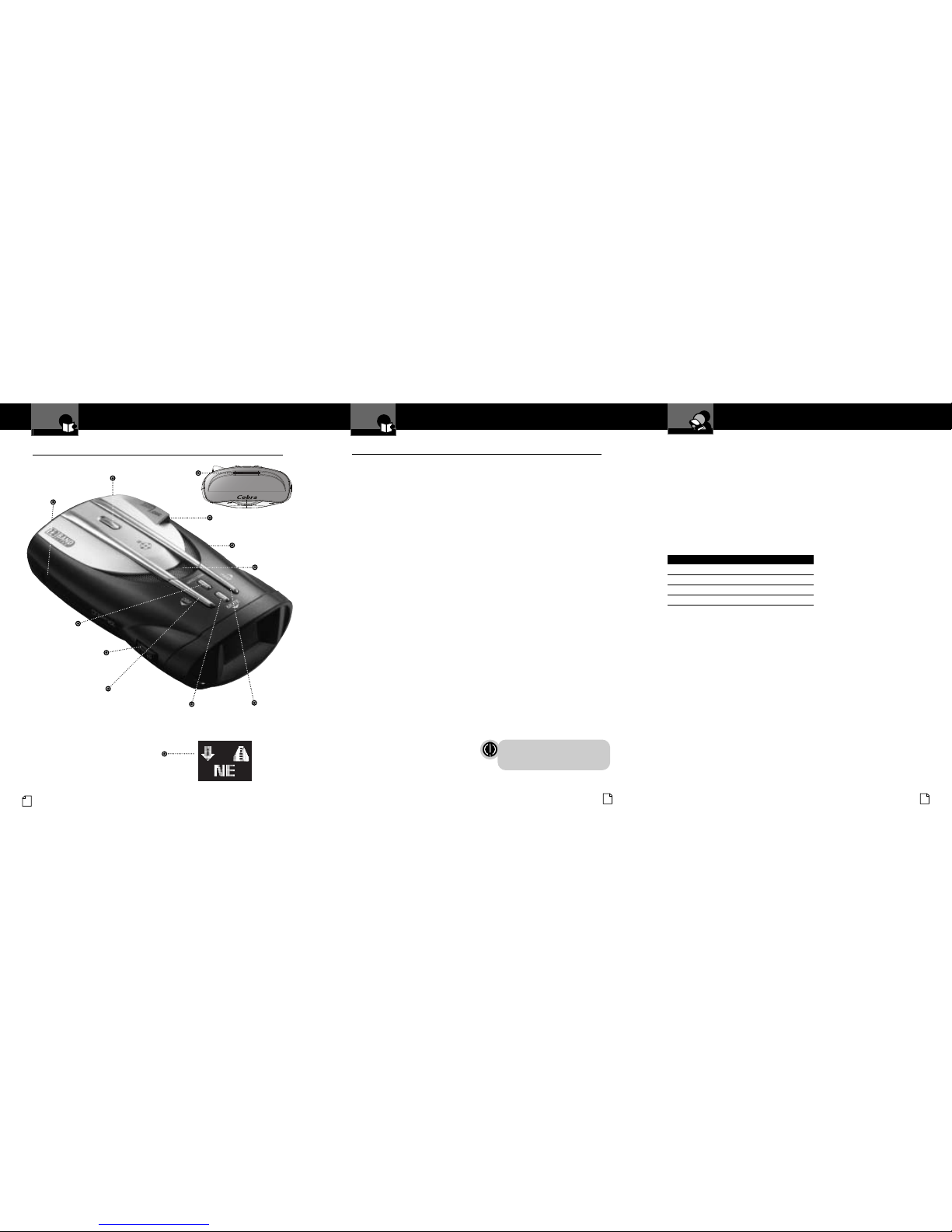
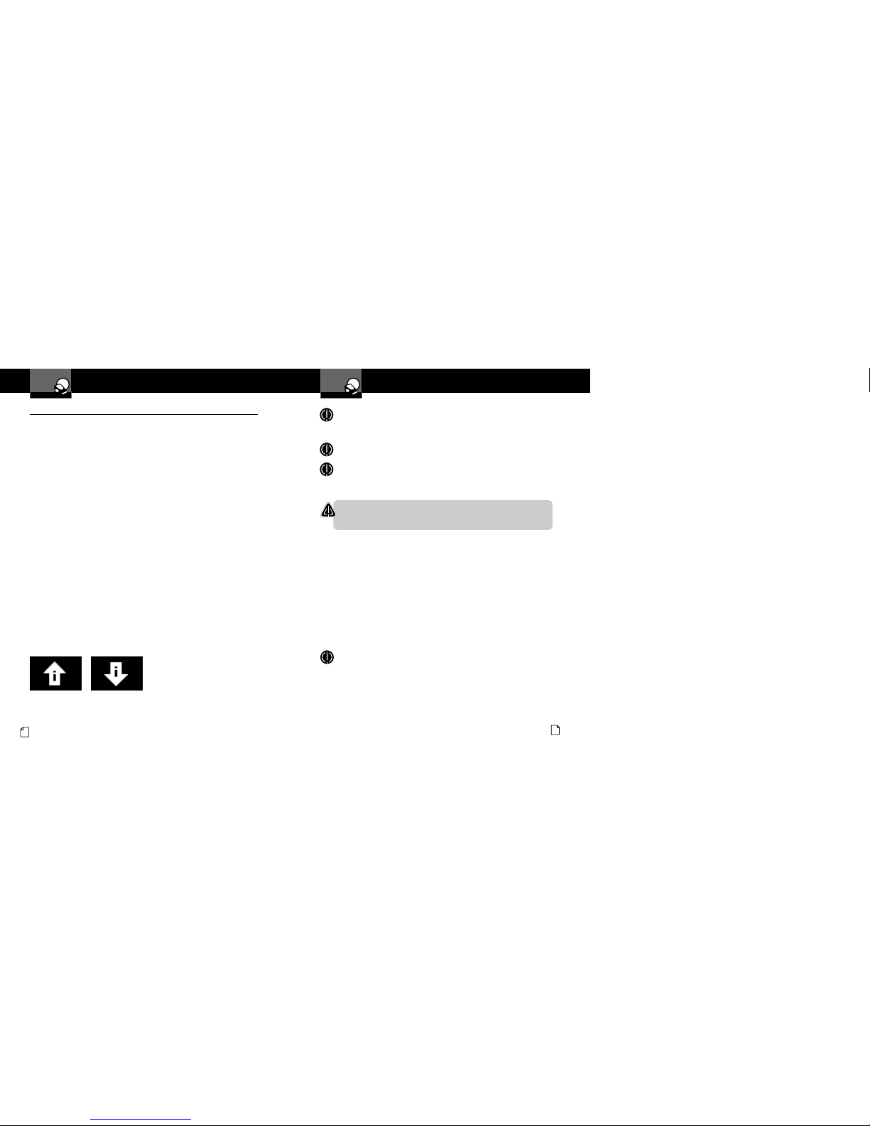
Controls, Indicators,
Connections and Display
Introduction
Controls, Indicators, Connections and Display •
12V DC
Power ack
On-Off/Volume Control
Allows user to adjust the volume
of the tone and voice alerts.
MuteButton
For manual mute of audio
alerts and to select/adjust
options while programming.
Menu/Save Button
Press once to enter
Program mode. Press
again to save settings.
LaserEye
For 360° detection of
laser and strobe signals.
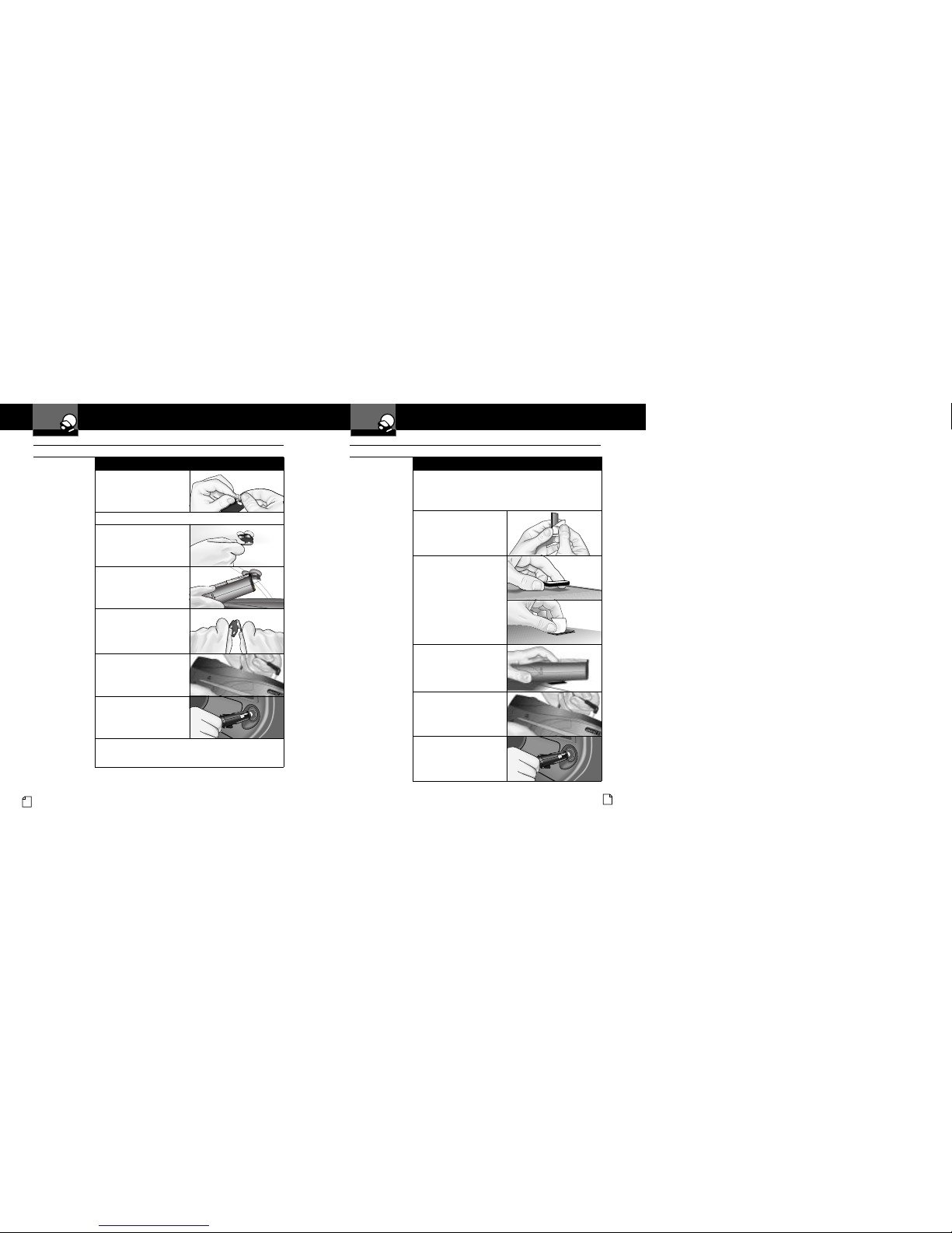
Windshield Bracket
Release Button
Speaker
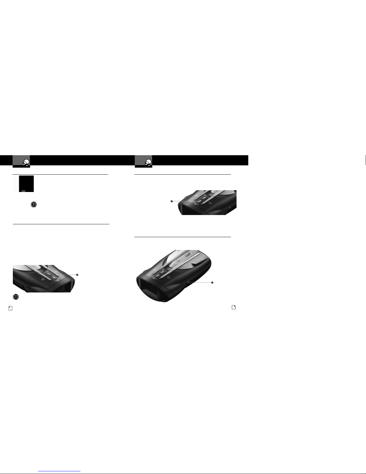
Auxiliary Audio
ack
DimButton
Adjusts the display brightness
and scrolls through option
settings while programming. CityButton
For changing between Highway and
City modes and to move forward
through options while programming.
Windshield Bracket
Mounting Slot
ExtremeBright DataGrafixTM Display
Blue sunlight-readable, extremely
bright display provides intuitive graphical
interaction and alert screens.
Nothing Comes Close to a Cobra®37
Product Features
Introduction
Nothing Comes Close to a Cobra®A3
Introduction
Xtreme Range
Superheterodyne Technology
With super-fast sweep circuitry,
XRS provides extra detection range
and the best possible advance warning
to even the fastest radar guns
Ultra Performance
Provides advanced warning with
extra detection range
Detection and Separate Alerts
For radar signals (X, K, Ka and Ku bands,
with signal strength indicated), laser
signals, Safety Alert signals, Strobe Alert
signals, V -2 signals, Spectre 1 signals
8-Point Compass
Displays direction of travel
LaserEye
For 360° detection of laser and
strobe signals
Instant-On Ready
Detects radar guns with “instant-on”
(very fast) speed monitoring capabilities
Pop Detection
Detects the latest super-fast radar guns
of the instant-on or single-pulse type
Voice or Tone Alert
With adjustable volume
ExtremeBright DataGrafixT Display
With easy-to-read graphical user interface
IntelliShield Highway/City odes
Reduces falsing in urban areas with
Highway mode and three levels
of City mode settings
Safety Alert
Traffic warning system distinguishes
important safety alerts from other
K band signals
Strobe Alert
Emergency vehicle warning system
anual ute or Auto ute
A mute function of audio alerts
Intelli ute
A mute function which automatically reduces
false alerts by sensing engine RPMs
SmartPower
A timed power saving function that
saves your car’s battery
EasySet Programming
User-friendly mode selection and
setting with visual guidance
Car Battery Voltage Display
Car battery voltage can be shown
continuously on the display
Car Battery Low Voltage Warning
Provides an alert when the car battery
voltage drops below 11.9 volts
Auxiliary Audio Jack
For external speaker connection
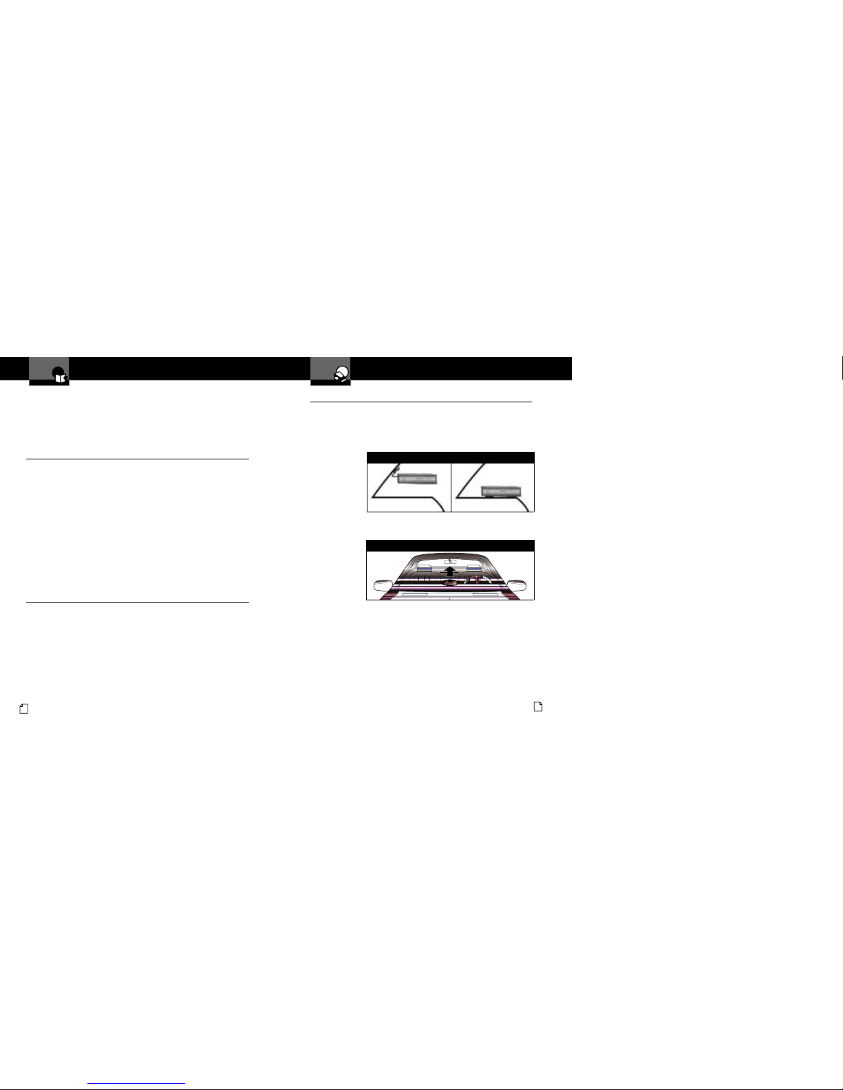
ounting
Mounts easily on windshield or dashboard
Product Features •
Congratulations! You’ve made a smart choice by purchasing an ultra high
performance digital radar/laser detector from Cobra. ust look at some of the
sophisticated features and capabilities your new unit includes:
WARNING
Mo ifications or parts substitutions not approve by
Cobra Electronics Corporation may violate FCC Rules
an voi your authority to operate this equipment.
Accessories Order Info
Customer Assistance
Ordering From U.S.A.
Call 773-889-3087 for pricing or visit www.cobra.com.
For Credit Card Orders
Call 773-889-3087 [Press one from the main menu] 8:00 a.m. to 6:00 p.m. Central Time,
Monday through Friday.
ake Check or oney Order Payable To
Cobra Electronics, Attn: Accessories Dept.,
6500 West Cortland Street, Chicago, IL 60707 U.S.A.
To Order Online
Please visit our website: www.cobra.com
Item # Description
420-030-N-001 Straight 12V P wer C rd
420-026-N-001 C iled 12V P wer C rd
545-159-N-001 Windshield M unting Bracket
CLP-2B Dual P rt P wer Adapter