manuals.online logo
Brands
  1. Home
  2. •
  3. Brands
  4. •
  5. Escort
  6. •
  7. Radar Detector
  8. •
  9. Escort Passport SR1 User manual

Escort Passport SR1 User manual

Important Note
1This product must be installed by a professional.
Please read the installation warnings inside.
2Please read this entire installation sheet before
beginning your installation.
3To ensure the high-performance radar and laser
detection that Escort detectors are known for, the
mounting location of the front receiver is critical.
Although Radar signals will go through some types
of plastic,Laser signals will not.It is very important
to mount the Front Receiver in a level position that
gives it a clear“view”of the road ahead.
The metal mounting brackets provided have several
different mounting holes,and can be used for most
vehicles.However,additional mounting hardware
may be required for some installations.
Installation Instructions for Passport SR1
For Professional Installation Only
Installation
1Slide 3”section of heat-shrink tubing over
connector,then connect receiver cable to
cable from Front Receiver. (Fit connectors
together,then twist large ring until it clicks.)
Do not shrink the heat-shrink tubing until
the detector is installed and operational.
2Route cable to firewall,secure with zip-ties.
3Route cable into interior.If there is not a
suitable opening,drill a 13/32”or 7/16”
diameter hole (slightly larger than 3/8”).
4Route wire inside interior and plug into
jack labeled“Receiver”on EZ-Interface.
5Pull grommet (provided on cable) into
position from vehicle interior to seal hole.
Use silicone sealant (not included) if
necessary for complete sealing.
Think first:
• Connector attaching to Front Receiver
cable must be positioned in a dry location
under hood,away from water spray.
• Only drill hole after thoroughly investigating
location and ensuring no other wires,hoses,
or other components will be damaged.
• Keep cable and connector away from
moving parts and hot surfaces (radiator,
heater hoses,exhaust components).
• Shielded cable– coil excess,do not splice.
Installation
1Determine best location for Receiver. The
best location is usually under the bumper
or just inside the grill.The unit must be
mounted with the arrows pointing forward.
(The radar antenna and laser sensors
“look”out the front of this unit,so it must
have a clear“view”of the road ahead.)
2Mark location,drill pilot holes in vehicle if
necessary.
3Mount large metal brackets to vehicle
with 4 sheet metal screws and lockwashers.
4Mount Receiver to large brackets with
four 8-32 machine screws and lockwashers.
5Route wire up to a dry location under hood
for the connector,secure with zip-ties.
Think first:
• Do not drill holes in Receiver.Mount only
to the preattached side and rear brackets.
• Only drill holes in vehicle after thoroughly
investigating location and ensuring no
other wires,hoses,or other components
will be damaged.
• Keep cable and connector away from
moving parts and hot surfaces (radiator,
heater hoses,exhaust components).
• Shielded cable– do not splice.
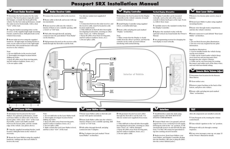
Front Radar and Laser Receiver
mountsunderbumperoringrille Receiver Cable connects
FrontReceivertoEZ-Interface
C
C
E
E
Hold here
BB
Slide 3” section of heat-shrink tubing over this
connector,thenconnectreceivercabletocable
from Front Receiver. (Carefully fit connectors
together,thentwistthis largeringuntil itclicks.)
After installation is complete and unit is opera-
tional, slide the heat-shrink tubing over the
connection, then shrink tubing for air-tight seal.
IMPORTANT
INSTALLATION
WARNINGS
Your new Passport SR1 must be
installed by a professional installer.
Installation of this product requires
experience and expertise in automo-
tive electronics. Car Audio specialists
andmanycardealerscaninstallPass-
port for you.
Attempting to install this product
withoutexpertiseinautomotiveelec-
tronicinstallationscancausepersonal
injury during the installation, or can
damage your Passport or your ve-
hicle.
If your vehicle is damaged during
installation, its safety systems may
be compromised, which could cause
personal injury or property damage.
Improper installation may void
Passport’s warranty.
BInstallation
Read this first!
Please read both sides of
these instructions before
starting your installation.
For the easiest trouble-
free installation, install the
EZ-Interface first, and wire it
to a 12 volt switched circuit.
Then before installing the
other components, plug all
three into the EZ-Interface
and power up unit to con-
firm proper operation.
See the other side of this
instruction sheet for addi-
tional mounting information.
THX1138
Installation
1Mount to rear license plate.
2Route wire through trunk into interior,
then conceal under trim and route and
plug into jack labeled“Rear Laser”on
EZ-Interface.
Think first:
• Do not block license plate illumination.
• Do not cover any required license plate
information.
Alternate Installations (hdwr. not incl.)
• Can be mounted elsewhere on rear of
vehicle.Brackets on Rear Laser Receiver
can be removed and turned 90º,then
used to mount unit beneath bumper.
• Can be installed inside car facing out
rear window.
• Cable can be routed under vehicle (take
care that cable cannot contact hot sur-
faces such as exhaust system) ,then
brought into interior with front cable.
• Cable can be cut if necessary for routing.
Reconnect and solder each of the three
conductors and seal with heat-shrink
tubing.
Installation
1Mount with velcro or double-sided
adhesive pad to instrument pod,dash-
board,or console.(Clean vehicle surfaces
thoroughly to ensure secure attachment.)
2Route wire and plug into EZ-Interface.
Think first:
• Make sure display is clearly visible and
controls can be easily reached from
driver’s seat position.
Alternate Installation
• Can be mounted vertically,such as on
the side of a console (volume knob goes
at the top).Carefully peel the standard
label from the front of the Display/
Controller,and replace with the supplied
Vertical label.
To program the Display for vertical read-
out,power the unit up. After the start-up,
hold the Mute and City buttons for 2
seconds.The display will read“Program.”
Then press the Review button once.The
display will read“Disp STD”(standard).
Then press the Change button once.The
display will change to“DispVERT”(vertical).
Wait 8 seconds as Passport saves your
programming.(See manual pages 8-12.)
Installation
1Mount inside vehicle under dashboard
with zip-ties. (Do not mount under hood.)
2Connect black wire to ground,connect
red-striped wire to switched 12 volt power.
(If Passport is left in the on position,it will
then automatically power-up each time the
car is started.) Use blue 3M connector
provided to tap into existing circuit.
3Receiver, Rear Laser, and Display cables
all plug into EZ-Interface.(Be sure to plug
all cables into the correct labeled jacks.)
EZ-Interface mountsunderdash,
connectstogroundandswitched12voltpower Display/Controllermountsto
dashorconsole,plugsintoEZ-Interface Rear Laser Sensormountsto
licenseplate,plugsintoEZ-Interface
Instructions for Passport SR1
Highway
Interior of Vehicle
Connect to switched
12 volts and ground
BBB
123
123
123
123
123
AFTER ALL COMPONENTS ARE INSTALLED
• TurnPassport volume knobto full.
• Turnignition switch on.Passport should power-up.
WatchDisplayfor messages “RearOK”and “Front OK”.
• IfDisplay reads “RearN/A”during the start-up
sequence,the Rear Laserisnot properly hookedup
(FrontReceiver will stilloperate).
• IfDisplay reads “FrontN/A”during the start-up
sequence,the Front Receiverisnot properly hookedup.
TheDisplay will thenshow“Check Receiver Wiring.”
Passportwill not operateuntilproblem is fixed.
• Ifthedisplaysaysboth“RearN/A”and“FrontN/A,”
checkto see iftheFront Receiver andRear Laser cables
arereversed at theEZ-Interface.
Connector for
optional remote
mute button
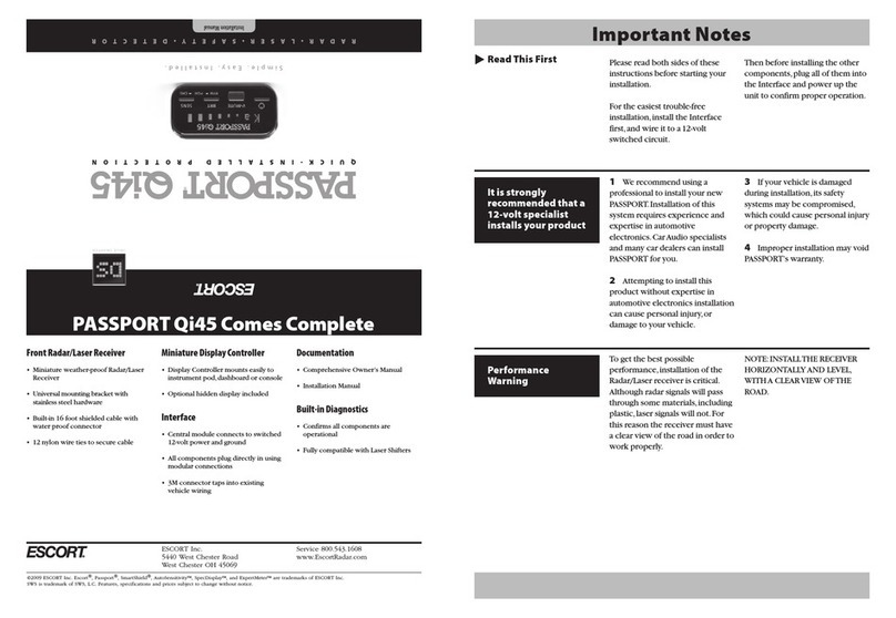
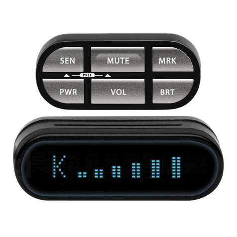
Display/Controller
• Miniature Display/Controller mounts to
instrument pod,dashboard or console.
• Vertical label provided for optional
mounting on side of console.
• Velcro and adhesive pad provided for
secure mounting
EZ Interface
• Convenient central module connects to
switched 12 volt power and ground
• All components plug in with modular
connectors
• 3M connector taps into existing wire
Passport SR1 comes complete
Rear Laser Sensor
• High-performance waterproof minia-
ture module
• Metal brackets attach to license plate
• Attached extra-long cable with modular
connector
Documentation
• Comprehensive 24 page owner’s
manual
• Installation instruction sheet
• Warranty registration card
Built-in diagnostics
• Confirms operation after installation
Escort Incorporated
5440West Chester Road
West Chester Ohio 45069
Technical Support 800-964-3143
Corporate Offices 513-870-8500
Fax 513-870-8509
www.escortradar.com
Front Radar and Laser Receiver
• Waterproof housing with attached metal
mounting brackets.
• Two universal metal mounting brackets
• Stainless steel mounting screws with
lockwashers for attaching brackets
• Stainless steel sheetmetal screws with
lockwashers for attachment to vehicle
• Shielded cable with connector
Receiver Cable
• Shielded cable with grommet and
connectors
• 12 Nylon wire ties to secure cables

Other manuals for Passport SR1

1

Other Escort Radar Detector manuals

Escort Max 360 User manual

Escort

Escort Max 360 User manual

Escort PASSPORT 8500CI Plus User manual

Escort

Escort PASSPORT 8500CI Plus User manual

Escort Passport MAX User manual

Escort

Escort Passport MAX User manual

Escort iX User manual

Escort

Escort iX User manual

Escort Passport Max2 User manual

Escort

Escort Passport Max2 User manual

Escort PASSPORT 9500ci User manual

Escort

Escort PASSPORT 9500ci User manual

Escort PASSPORT S55 User manual

Escort

Escort PASSPORT S55 User manual

Escort Passport 9500ix User manual

Escort

Escort Passport 9500ix User manual

Escort Redline Ex User manual

Escort

Escort Redline Ex User manual

Escort MAX 3 User manual

Escort

Escort MAX 3 User manual

Escort Solo S3 User manual

Escort

Escort Solo S3 User manual

Escort iX User manual

Escort

Escort iX User manual

Escort Shifter ZR3 User manual

Escort

Escort Shifter ZR3 User manual

Escort Passport MAX User manual

Escort

Escort Passport MAX User manual

Escort Passport SR1 User manual

Escort

Escort Passport SR1 User manual

Escort PASSPORT iQ User manual

Escort

Escort PASSPORT iQ User manual

Escort Passport MAX User manual

Escort

Escort Passport MAX User manual

Escort Passport 7500 User manual

Escort

Escort Passport 7500 User manual

Escort iX Ci PLATFORM User manual

Escort

Escort iX Ci PLATFORM User manual

Escort Passportmax User manual

Escort

Escort Passportmax User manual

Escort iX User manual

Escort

Escort iX User manual

Escort PASSPORT 9500ci User manual

Escort

Escort PASSPORT 9500ci User manual

Escort Passport 8500 User manual

Escort

Escort Passport 8500 User manual

Escort PASSPORT Qi45 User manual

Escort

Escort PASSPORT Qi45 User manual

Popular Radar Detector manuals by other brands

Whistler PRO-69Ru owner's manual

Whistler

Whistler PRO-69Ru owner's manual

Cobra XRS 9540 operating instructions

Cobra

Cobra XRS 9540 operating instructions

SENSORO ZODIAC II Operation manual

SENSORO

SENSORO ZODIAC II Operation manual

Whistler XTR-338 owner's manual

Whistler

Whistler XTR-338 owner's manual

Whistler 1785 owner's manual

Whistler

Whistler 1785 owner's manual

Whistler PRO-3600 owner's manual

Whistler

Whistler PRO-3600 owner's manual

Cobra SPX 5400 operating instructions

Cobra

Cobra SPX 5400 operating instructions

Cobra ESD-9570 supplementary guide

Cobra

Cobra ESD-9570 supplementary guide

Whistler PRO-68SE owner's manual

Whistler

Whistler PRO-68SE owner's manual

Beltronics BEL975R - BEL VECTOR LR Remote Radar/laser... owner's manual

Beltronics

Beltronics BEL975R - BEL VECTOR LR Remote Radar/laser... owner's manual

GENEVO One S Black Edition user manual

GENEVO

GENEVO One S Black Edition user manual

Whistler XTR-145 owner's manual

Whistler

Whistler XTR-145 owner's manual

Cobra XRS 9445 operating instructions

Cobra

Cobra XRS 9445 operating instructions

Uniden GPS9000NZ owner's manual

Uniden

Uniden GPS9000NZ owner's manual

Whistler GT-130Xi owner's manual

Whistler

Whistler GT-130Xi owner's manual

Cobra 15 BAND XRS R8/R106 operating instructions

Cobra

Cobra 15 BAND XRS R8/R106 operating instructions

Cobra XRS R10G operating instructions

Cobra

Cobra XRS R10G operating instructions

Hit-Not DDAC-PDS-SYS-2 installation guide

Hit-Not

Hit-Not DDAC-PDS-SYS-2 installation guide

manuals.online logo
manuals.online logoBrands
  • About & Mission
  • Contact us
  • Privacy Policy
  • Terms and Conditions

Copyright 2025 Manuals.Online. All Rights Reserved.