Cocoon Cooltech User manual

Cooltech
SERVICE MANUAL
Service Manual Cooltech
V1.1

Service Manual Cooltech
Content
1. Equipment description ........................................................................................................................................ 3
1.1. Unpacking and installation ........................................................................... ¡Error! Marcador no definido.
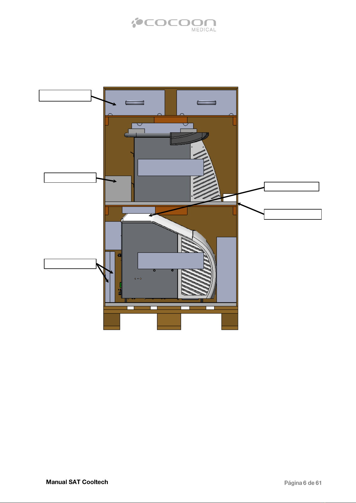
1.2. Equipment components ............................................................................... ¡Error! Marcador no definido.
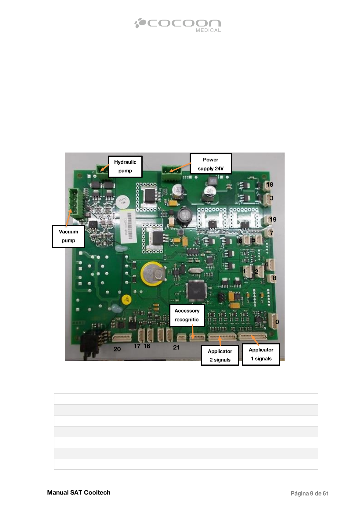
1.2.1. Electronics........................................................................................................................................... 8
1.1.1. Refrigeration system............................................................................ ¡Error! Marcador no definido.
1.1.2. Vacuum system.................................................................................... ¡Error! Marcador no definido.
1.2. Equipment maintenance and accessories .................................................... ¡Error! Marcador no definido.
1.2.1 - External tanks cleaning ........................................................................................................................... 13
1.2.2 - Air filter cleaning (ventilation) ................................................................................................................ 13
1.2.3 - Applicators internal cleaning................................................................................................................... 13
2. Sat tools ................................................................................................................ ¡Error! Marcador no definido.
2.1. SAT codes...................................................................................................... ¡Error! Marcador no definido.
2.2. Tools and special utilities.............................................................................. ¡Error! Marcador no definido.
2.3. Report incidents ........................................................................................... ¡Error! Marcador no definido.
2.4. Software update ........................................................................................... ¡Error! Marcador no definido.
3. Troubleshooting and alarms ................................................................................ ¡Error! Marcador no definido.
3.1. Screen alarms ............................................................................................... ¡Error! Marcador no definido.
3.1.1 - Low coolant level..................................................................................................................................... 22
3.1.2 - High or low pressure hydraulic circuit..................................................................................................... 22
3.1.3 - Emergency stop actived .......................................................................................................................... 25
3.1.4 - High or very low equipment temperature warning ................................................................................ 26
3.1.5 - Vacuum circuit cleaning reminder .......................................................................................................... 27
3.1.6 - Applicator disconnected.......................................................................................................................... 27
3.1.7 - Applicator temperature error ................................................................................................................ 29
3.1.8 -Applicator programmed vacuum not reached......................................................................................... 31
3.2. Equipment faults .......................................................................................... ¡Error! Marcador no definido.
3.2.1 - Equipment does not turn on .................................................................................................................. 35
3.2.2 - Accessories not recognized ..................................................................................................................... 38
3.2.3 - Screen does not respond ........................................................................................................................ 40
3.2.4 –Lined screen............................................................................................................................................ 41
3.2.5 - Treatment screen not allowed ................................................................................................................ 42
3.2.6 - Set temperature not reached.................................................................................................................. 44

3.2.7 - Applicators temperature does not decrease........................................................................................... 46
3.2.8 - Equipment does not decrease below 0 ° C.............................................................................................. 50
3.2.9 –Equipment does not suck ....................................................................................................................... 51
3.2.10 –Suction losses ....................................................................................................................................... 54
3.3–Report incidents ............................................................................................................................................... 80
4. Spare part list ....................................................................................................¡Error! Marcador no definido.
5. Technical data....................................................................................................¡Error! Marcador no definido.

PACKING ACCESSORIES
Accesorio
Each accessory is wraped in a plastic
bag and placed in the box A4.02266.
+
A4.01454 x2
+
+
+
A4.01454 x2
A4.01454 x2
A4.01455
+
A4.01455

+
+
+
+
+
+
A4.01454 x2
A4.01453
A4.01454
A4.01455
A4.01455
A4.01455 x2
+
+
x2 x2

APPLICATORS PACKAGING
Ref. of packaging EMB-23.XX. Cooltech applicator packaging.
MANUALS PACKING
BOX A4.01391A.

Packing layout
A4.02266
A4.01389 x2
A4.01591
A4.01391
A4.01415


Cooltech equipment consists of 3 large blocks: an electronic block - for control of all inputs and
outputs of the equipment, a refrigeration block –for cooling the hot part of the peltiers and a
vacuum block - for stopping blood circulation in the treated area, avoiding heating the area for
better results. Each of these blocks is described in more details below.
Electronics:
The electronic block consists of 2 CPUs: the Main and TFT control board.
Main CPU TFT control board
Main CPU is located inside the electic cabinet of the equipment (on the left side, viewed from the
front), while TFT control board is mounted underneath the display.
TFT control board is responsible for displaying the necessary images on the screen, analyzing
and informing the Main CPU, when the user enters any data and commands on TFT.
All images, graphics and active zones for the screen are stored on a microSD inserted in TFT
control board.

This memory card should have maximum capacity of 2GB and format to FAT32 clouster 4096.
On the microSD are stored only 3 '.ars' files: PrjAreas.ars, RrjIcons.ars and PrjImages.ars. If exist
other files, may appear an error while the software is being loaded.
Main CPU is responsible for controlling temperature, vacuum and refrigeration of each applicator,
reading the information from all inputs (sensors, switches, power supplies, resistors ect.) and
activating any of outputs (pumps, peltiers, electrovalves ect.) in different moments and also
sending the relevant feedback to the screen.
The following figure shows all cables connection to Main CPU
Main CPU connections
Nº cable
Description
0
Level sensor for deposit tank
1
Electrovalve 1
2
Electrovalve 2
3
Electrovalve 3
4
Electrovalve 4
5
Ventilator radiator

1.1.1. Refrigeration system
6
Ventilator radiator
7
Ventilator electronics
8
Emergency button
16
Control cable (peltier power supply) applicator 2
17
Control cable (peltier power supply) applicator 1
18
Buzzer
19
Backlight TFT
20
Communication cable + power supply 24V TFT
21
Internal temperature sensor

1.1.2. Vacuum system

General considerations for cleaning and maintenance:
- For safety reasons, before cleaning the equipment, it is recommended to disconnect the
power cord from power socket.
-For methacrylate surfaces, pay great attention in the use of cleaning products. If this
material comes in contact with substances such as alcohol, solvents, ammonia or other
aggressive products (thinners, acetone ...), it reacts forming "cracks", which are not visible
immediately but in the next days.
- To clean this material, it is recommended to use specific methacrylate products such as
"Vetril" or use a well squeezed cloth or soft paper after being soaked in water with diluted neutral
soap.

- It is recommended to clean and sanitize the applicators of the equipment after each
treatment. To do this, remove the product residues (gel) deposited in the applicator, clean and
disinfect the applicator before using again. Do not use products containing alcohol.
- For outside cleaning of the casing, dry thoroughly using synthetic fabrics before starting a
new treatment.
-Do not immerse the applicator in any liquid
1.2.1 - External tanks Cleaning
To clean external tanks, the tubes connecting each tank to the equipment must be disconnected.
Press the grey clips of the connectors and pull them out, in this way the tank will be totally
independent from the equipment.
Once the connectors have been removed, take the tank out of its holder carefully. To make
complete cleaning, disconnect the air filter from the tank and the hose.
Remove the cap from the tank and wash both parts with plenty of water.
Then close the tank again, install the filter (explained later), put it back inside its holder and
connect the tubes in their corresponding inputs. Make sure that it is properly placed in the holder
and that the tubes are not bent. The position of the connectors is indicated with colors (only on
some models). Checked carefully that the tank is well closed, otherwise the equipment will not
operate correctly and will not reach the desired vacuum.
1.2.2 - Air filter cleaning (ventilation)
At the bottom of the equipment there is an air filter to prevent entering dust iside the unit. To
remove the filter, just pull it. This filter should be cleaned once every month.
To clean it, use a vacuum cleaner or shake it. The filter should be changed once a year. To
supply these filters, contact the manufacturer.
Replacement of antibacterial vapor filter
When the filter is dirty and the suction power is insufficient in its corresponding applicator,
proceed to replace it.
The bacterial filter is connected to two tubes, one goes from the filter to the equipment
connector, the other from the filter to the tank. Replace the filter by disconnecting the pipes by
pulling slightly and progressively. Connect the new filter in the same position as the old one,
matching the color band of the tube connected to the equipment with the color band incorporated
on the filter.
1.2.3 - Applicator internal cleaning
It is necessary to perform periodically a cleaning of the applicators, because of the gel that is
going inside and clogging the hose during the treatments.
This proplem leads to a progressive loss of the suction capacity of the applicator, reaching the
point that the hand piece stops sucking comletely (totally obstructed line).
The periodicity of cleaning is related to the number of treatments and the amount of gel that is
used.
Important: Before start cleaning, disconnect the equipment from the power socket.
To clean an applicator, disconnect the tube in the back of the equipment that has a red color
band, connecting the tank with the machine.
Important: Perform the operation with the tank corresponding to the applicator.

Press the grey clip of the female connector to disconnect the tube and then pull slightly and
progressively from the tank.
During the cleaning process, it is recommended to keep the applicator on higher position so that
the liquid injected with the cleaning tool supplied with the equipment, not return.
Then insert the end of the cannula tube into the internal input of the applicator and inject the
distilled water contained in the cannula. Remove the tube from the hole. Fill the cannula with air
and inject it in the same way in order to clean thicker gel residues.
Repeat these operations (first distilled water and then air) until flows clean water on the back of
the equipment.
Important: Be careful during the cleaning process not to overfill the tank on the back of the
machine, corresponding to the applicator being cleaned, otherwise will damage the paper filter.
Always empty before filling.
At the end of the cleaning, perform several more operations with air only, to blow out any water
left in the hose.
Then empty and clean the tank. To do this, remove the cap and wash out all the gel residues.
Replace the cover.
The tank should be closed properly: carefully tighten all tank clips (otherwise will be observed
vacuum drops during the treatment).
Once the applicator or applicators have been cleaned, as well as the tank, proceed to reconnect
the tanks, as explained in section 2 of the equipment installation. Remember that tanks have a
single connecting position. Take into account that the color band of tank and equipment match
and the paper filter is on the right of the reservoir.
Codes, enabling access to different functions, specific settings and parameters of the equipment, that
could be monitored and modified. To do this enter the code screen, then enter the relevant code and
press 'Enter'.

Description of the equipment and incidence Problem related to the security
Model:
Serial number
(S/N):
YES
Technical
service report
No.
Conditions:
Warranty
Internal
Customer:
Contract
Demo
Cargo
Customer
Direction:
Installation
Other
Date of
incident :

Software version:
NO
Applicator:
Serial number:
Incidence specifications:
Repair specifications:
Materials for repair:
Part
No.
Component
Quantity
Description
Price
Software updated Ver:
Details: - Filled by the manufacturer
Warranty details:
Replace:
Repair:
RMA no.:

Before starting the software update of the equipment, it is necessary to access the Main CPU. Remove
the left cover of the equipment by unscrewing the 3 rear screws, as shown on the image1 and access to
the electro cabinet (Image2):
Once the PCB of the equipment is located, connect the AVR programmer to the PCB. Pay attention on
the connector position:
Start the previously installed Atmel Studio, turn the equipment on and follow the steps:

1. Select "Tools -> Device Programming" as shown in the image:
2. Configure the necessary data for the programming:in the "Tool" drop-menu select "Atmel-ICE" and in
the drop-menu "Device" select "ATmega128". Then press the "Apply" button.
3. Before programming it is necessary to read and save the EEPROM information for the equipment. To
make this procedure, go to the "Memories" tab and click the "..." button in the EEPROM section:

4. Specify the location for saving the file and its name. Then click the "Save" button and finally click the
"Read" button:
5. Click the "..." button as shown in the image and select the appropriate Cooltech program (.hex file)
in the Flash section. Then select the EEPROM file previously saved. Click on the "Program" button in
the Flash section:
Table of contents
Other Cocoon Medical Equipment manuals
Popular Medical Equipment manuals by other brands

Ormesa
Ormesa Birillo Use and maintenance handbook

Smiths Medical
Smiths Medical Surgivet Advisor Quick reference guide

baxter
baxter TruLight 5000 Instructions for use

Dräger Medical
Dräger Medical Inhalog 1 plus Instructions for use

Atmos
Atmos LC 27 operating instructions

Sirona
Sirona Galaxis operating manual