Force Dimension lambda.7 haptic device User manual
USER MANUAL
lambda.7 haptic device
version 1.0
Force Dimension
Switzerland
www.forcedimension.com

2

3
Summary
The purpose of this document is:
>to describe the setup of the lambda.7 haptic device,
>to describe the installation of the software drivers and the Force Dimension SDK,
>to describe the basic operation modes of the lambda.7 haptic device.

4

5
Table of contents
System overview 6
Important safety instructions 7
Setting up the lambda.7 haptic device 8
3.1 Haptic device installation 8
3.2 Installing the power supply 13
3.3 Connecting the lambda.7 haptic device to your computer 13
3.4 Software installation 13
Configuring the lambda.7 under Windows 14
4.1 Installing the software 14
4.2 Installation description 14
4.3 Installing the drivers 14
Configuring the lambda.7 under Linux 15
5.1 Installing the software 15
5.2 Installation description 15
5.3 Installing the drivers 15
Configuring the lambda.7 under macOS 16
6.1 Installing the software 16
6.2 Installation description 16
6.3 Installing the drivers 16
Operating the lambda.7 17
7.1 Coordinate system 17
7.2 Operating modes 19
7.3 Running the Haptic Desk program 20
7.4 Running the demonstrations programs 21
Technical information 23

6
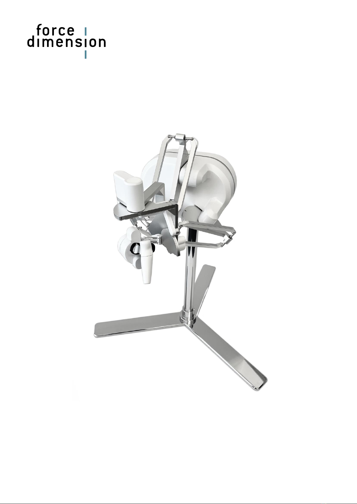
System overview
Figure 1 –Overview of the lambda.7 haptic device
1. device stand rear leg
2. device stand front legs
3. device stand pole
4. haptic device controller
5. arms of translational base
6. rotational wrist
7. end-effector (force gripper handle)
8. pole interface
9. power switch
10. power connector
11. USB connector
7
1
10
8
2
3
5
4
11
9
6

7
Important safety instructions
IMPORTANT
WHEN USING THIS HAPTIC DEVICE, BASIC SAFETY PRECAUTIONS
SHOULD ALWAYS BE FOLLOWED TO REDUCE THE RISK
OF FIRE, ELECTRICAL SHOCK, OR PERSONAL INJURY.
1. Read and understand all instructions.
2. Follow all warnings and instructions marked on your haptic device.
3. Do not use or place your haptic device near water.
4. Place your haptic device securely on a stable surface.
5. Make sure that the workspace of your haptic device is free of objects.
6. Do not overload wall outlets and extension cords as this can result in a risk of fire or electri-
cal shock.
7. Switch off your haptic device when it is not in use.
8. To reduce the risk of electrical shock, do not disassemble your haptic device.

8
Setting up the lambda.7 haptic device
This section describes the different steps to follow to safely setup your lambda.7 device before
use.
IMPORTANT
PLEASE KEEP THE ORIGINAL PACKAGING
ONLY USE THE ORIGINAL PACKAGING DURING STORAGE OR SHIPMENT
3.1 Haptic device installation
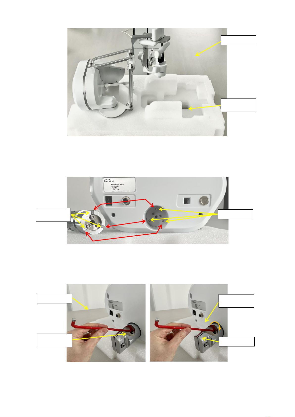
The lambda.7 haptic device is shipped in three cardboard boxes. Please start by opening the
larger of the three boxes which contains the lambda.7 haptic device controller and accessories,
as illustrated in figure 2.
Figure 2 –Transportation box which contains the lambda.7 device controller and accessories.
Among the accessories included with the haptic device are nine screws and an orange hex key
that are required to assemble the device stand contained in the two smaller cardboard boxes. The
haptic device controller is mounted at the end of the setup procedure and is therefore best kept
in its protective box until then.
The operations described in the following steps are best performed by a team of two people.
power cable
haptic device
controller
power supply
user manual
pole interface
accessories
USB cable

9
The lambda.7 support stand is composed of three legs and one mast which are illustrated in fig-
ures 3 and 4. These parts can be found in the two cardboard boxes that come with the unit.
Figure 3 –stand pole (1x)
Figure 4 –stand leg (3x)
The three legs are mounted to the pole by securely fastening the nine stand screws (three screws
per leg) using the orange hex key, as shown in figure 5. The screws and orange hex key can be
found in the plastic case that contains the haptic device controller.
Figure 5 –Mounting the device stand legs onto the pole.
orange hex key
stand legs
stand screws
stand pole

10
Once the device stand is mounted, the upper foam layer with the accessories may be lifted out of
the box, thereby revealing the lambda.7 haptic device controller, as shown in figure 6.
Figure 6 –Shipping box containing the lambda.7 device after removal of the upper foam layer.
Place the upper foam layer upside down on a flat surface.
Carefully extract the haptic device from the carboard box and place the system on its upper foam
layer as shown in figure 8. This will protect the haptic device during preparation.
Finally, remove the protective foam which secures the wrist and gripper handle.
Figure 7 –Lifting the haptic device out of its shipping box.
haptic device
controller
11
Figure 8 –The haptic device shall be placed on its flipped upper foam layer on a flat surface for preparation.
Insert the pole interface at the rear of haptic device controller by making sure that the groves of
the pole interface align with the spherical contact points on the device.
Figure 9 –Aligning the pole interface with the contact points of the lambda.7 haptic device.
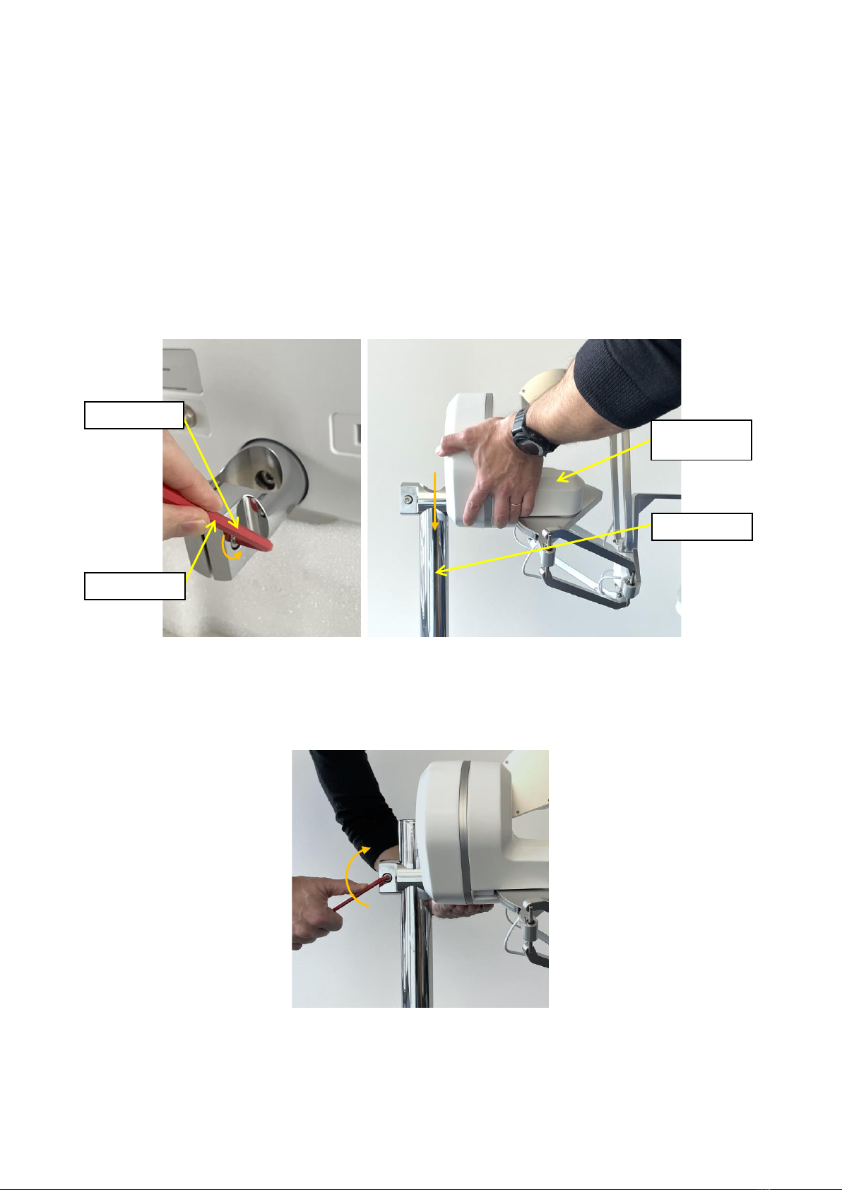
Securely fasten the tightening screw by using the red hex key, as illustrated in figure 10.
Figure 10 –Mounting the pole interface to the haptic device controller with the help of the tighten-
ing screw.
flipped upper
foam block
tabletop
pole interface
contact points
alignment
grooves
tightening
screw
clamping
screw
red hex key
12
By using the same red hex key, loosen the clamping screw as illustrated on the left image of figure
11.
Finally, mount the lambda.7 device base on its stand pole by sliding it from the top, as shown on
the right image of figure 11. Place the haptic device controller at the desired height and lock the
mechanism by fastening the clamping screw.
Verify that the device is correctly secured by making sure that the device base cannot rotate
around its vertical stand pole. If any slippage occurs, further tightening of the clamping screw may
be required.
Figure 11 –After loosening the clamping screw, the haptic device controller can be mounted on the stand
pole.
Figure 12 –Fastening the clamping screw while holding the device with the opposite hand.
Your lambda.7 haptic device is now fully assembled. You may place the haptic device at your con-
sole desk where you will be operating the system.
clamping screw
leg
red hex key
stand pole
haptic device
controller
13
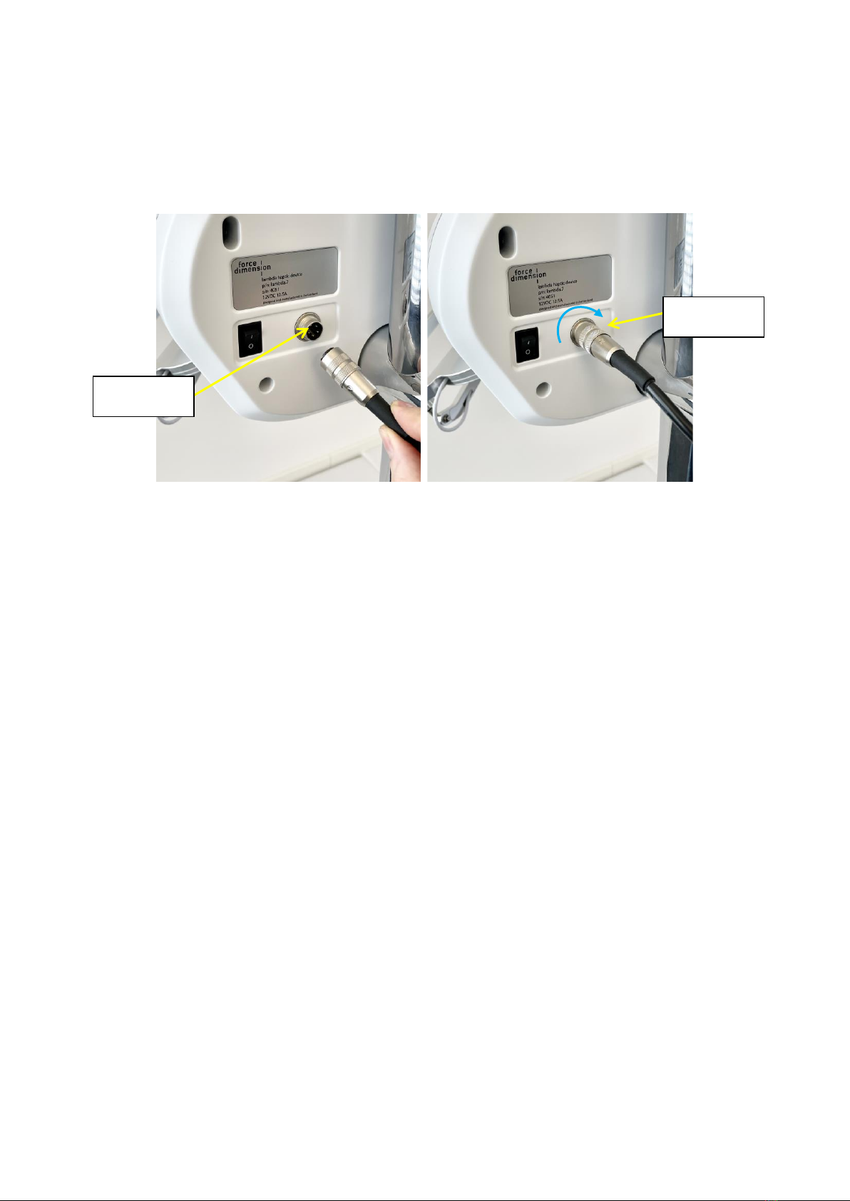
3.2 Installing the power supply
Plug and tighten the power supply into the power connector. For safety purposes you should only
operate your lambda.7 haptic device using the original power supply that came with your haptic
device controller. Replacement power supplies can be ordered directly from Force Dimension.
Figure 13 –Connection and tightening of the power connector.
3.3 Connecting the lambda.7 haptic device to your computer
Connect the lambda.7 haptic device to your computer using the USB cable which is included in
the box.
3.4 Software installation
A USB flash drive, located with the accessories, includes the drivers and SDK installation media
for the different operating systems.
power
connector
alignment
groove

14
Configuring the lambda.7 under Windows
4.1 Installing the software
The USB driver must be first installed onto your system prior to connecting the lambda.7 to the
computer. To do this, perform the following steps:
1. Plug the Force Dimension USB flash drive into your Windows computer.
2. Open the \Windows folder on the USB flash drive and select the appropriate \32-bit or \64-
bit subfolder according to the operating system version on your computer.
3. Run the installation program and follow its instructions.
4.2 Installation description
The installation program creates the following subfolders in:
C:\Program Files\Force Dimension\sdk-<version>
\bin subfolder
This directory contains the demonstration executables and the DLL files required to run the
lambda.7 software. The required DLL files are also copied to the Windows system folder during
the installation.
\drivers subfolder
This directory contains the USB drivers required to operate your haptic device.
\examples subfolder
This directory contains the demonstration programs. Example applications described in section
7.4 and come with their full source code.
\doc subfolder
All documentation files and notices are located in that directory.
\manuals subfolder
All hardware user manuals are located in that directory.
\lib,\include subfolders
These directories contain the files required to compile your application with the Force Dimension
SDK. Please refer to the on-line programming manual for more information (see subfolder\doc).
4.3 Installing the drivers
USB drivers
The lambda.7 requires the Force Dimension USB driver. These drivers are installed automatically,
and no additional step is required.

15
Configuring the lambda.7 under Linux
5.1 Installing the software
The Force Dimension development folder must be installed onto your system before the lambda.7
can be used. To do this, perform the following steps:
1. Plug the Force Dimension USB flash drive into your Linux computer.
2. Extract the sdk-<version>.tar.gz archive for your system architecture from the \Linux
subfolder to the desired location (typically your home folder) by running the following com-
mand within the target folder:
tar –zxvf sdk-<version>.tar.gz
This will create a sdk-<version> development folder in the target location.
5.2 Installation description
The development folder contains the following directories:
\bin subfolder
This directory contains the demonstration executables and the binary files required to run the
lambda.7 software.
\examples subfolder
This directory contains the demonstration programs. Example applications described in section
7.4 and come with their full source code.
\doc subfolder
All documentation files and notices are located in this subfolder.
\manuals subfolder
All hardware user manuals are located in that directory.
\lib,\include subfolders
These directories contain the files required to compile your application with the Force Dimension
SDK. Please refer to the on-line programming manual for more information (see subfolder\doc).
5.3 Installing the drivers
The Linux version of the Force Dimension SDK requires the development packages for the
libusb-1.0 to be installed on your Linux distribution.
IMPORTANT
PLEASE NOTE THAT USB ACCESS TO THE HAPTIC DEVICE REQUIRES SUPERUSER
PRIVILEDGES ON MOST LINUX DISTRIBUTIONS

16
Configuring the lambda.7 under macOS
6.1 Installing the software
The Force Dimension development folder must be installed onto your system before the lambda.7
can be used. To do this, perform the following steps:
1. Plug the Force Dimension USB flash drive into your Apple computer.
2. Open the sdk-<version>.dmg file for your version of macOS from the \macOS folder and
extract the sdk-<version> folder to the desired location (typically your home folder).
This will create a sdk-<version> development folder in the target location.
6.2 Installation description
The development folder contains the following directories:
\bin subfolder
This directory contains the demonstration executables and the binary files required to run the
lambda.7 software.
\examples subfolder
This directory contains the demonstration programs. Example applications described in section
7.4 and come with their full source code.
\doc subfolder
All documentation files and notices are located in this subfolder.
\manuals subfolder
All hardware user manuals are located in that directory.
\lib,\include subfolders
These directories contain the files required to compile your application with the Force Dimension
SDK. Please refer to the online programming manual for more information (see subfolder\doc).
6.3 Installing the drivers
The macOS version of the Force Dimension SDK uses Apple’s native USB drivers. No further instal-
lation is required.
17
Operating the lambda.7
7.1 Coordinate system
base translation
The position of the center of the end-effector (handle) is expressed in Cartesian coordinates and
in IUS (metric) units. Figure 14 illustrates the coordinate system. You will notice that the Z-axis of
the coordinate system is parallel to the first revolute axis of the wrist.
The actual origin of the coordinate system (0,0,0) is located on a virtual point situated at the cen-
ter of the physical workspace of the haptic device.
Figure 14 –Cartesian coordinate system of the lambda.7 haptic device
X-axis
Y-axis
Z-axis

18
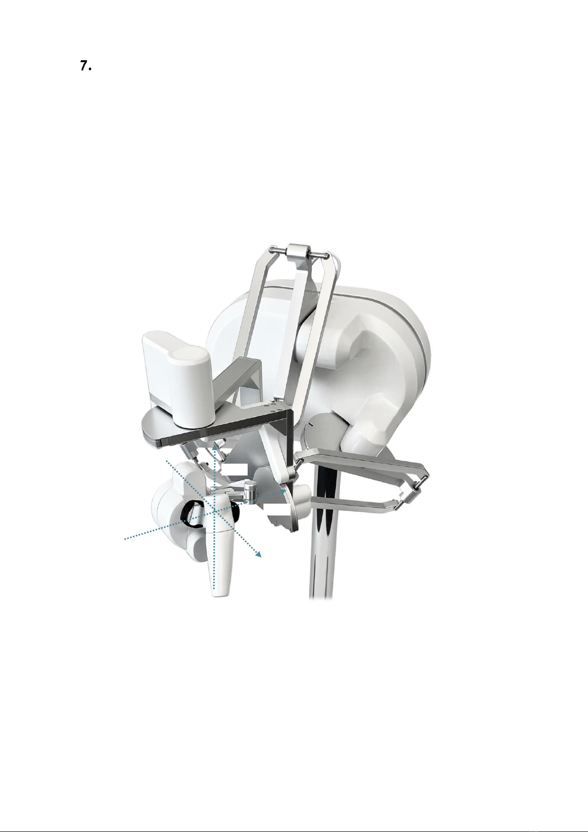
wrist orientation
The orientation of the lambda.7 haptic device is expressed by a reference frame Rwrist which is nu-
merically represented using a 3x3 rotation matrix. This reference frame is expressed in relation to
the world coordinate system described in figure 14.
The reference frame of the wrist is computed from the angle values returned by the joint sensors
mounted of each revolute axis of the wrist as illustrated in figure 15. When all joint angles are
equal to zero, an identity rotation matrix is returned.
Figure 15 –Reference frame of the wrist of the lambda.7 haptic device
gripper angle
The angular position of the force gripper is returned in either degrees or radian.
A positive angle value is returned for right-hand lambda.7 haptic devices. A negative angle value
is returned for left-hand haptic devices.
Angular values closer to zero correspond to configurations where the force gripper is in a closed
configuration. Opening of the force gripper increases the magnitude of the angle.
wrist axis 0
wrist axis 1
wrist axis 2
wrist reference frame Rwrist

19
7.2 Operating modes
calibration
Calibration of the haptic device controller is necessary to obtain accurate, reproducible localiza-
tion of the end-effector within the workspace of the haptic device. The lambda.7 is designed in
such a way that there can be no drift of the calibration over time, so the procedure only needs to
be performed once each time the device is powered ON.
The automatic calibration procedure is performed by software using the Force Dimension SDK, for
example by launching the application "HapticInit" which automatically drives the device through-
out its workspace. Please do not touch the device during this automatic calibration procedure.
After calibration, the device is ready for normal operation.
gravity compensation
To prevent user fatigue and to improve dexterity during manipulation, the lambda.7 features grav-
ity compensation. When gravity compensation is enabled, the weights of the arms and of the end-
effector are taken into account and a vertical force is dynamically applied to the end-effector in
addition to the desired user force command. Please note that gravity compensation is computed
on the host computer, and therefore only gets updated every time a new force command is sent to
the haptic device by the application. Gravity compensation is enabled by default and can be dis-
abled through the Force Dimension SDK.
forces
By default, and when an application opens a connection to the haptic device controller, all forces
are initially disabled. Forces can be enabled or disabled through the Force Dimension SDK.
brakes
The device features electromagnetic brakes that can be enabled through the Force Dimension
SDK. These brakes are enabled by default every time the forces are disabled. When the brakes are
engaged, a viscous force is created that prevents rapid movement of the end-effector.
20
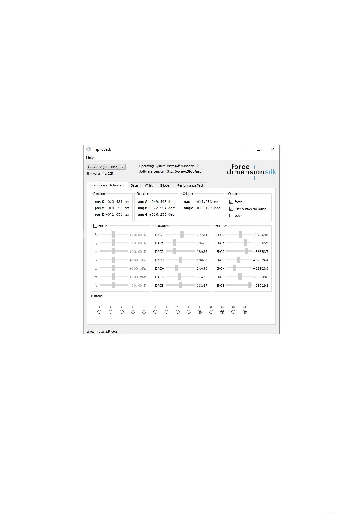
7.3 Running the Haptic Desk program
The Haptic Desk application is available as a test and diagnostic program and offers the following
capabilities:
>list all Force Dimension haptic devices connected to the system,
>test the position reading of the haptic device in Cartesian coordinates,
>test all force and torque capabilities of the haptic device,
>test the active locks,
>run the auto-calibration procedure,
>read the haptic device status,
>read the haptic device encoder sensors individually,
>read the simulated user button.
Figure 16 –Haptic Desk test and diagnostic program
Table of contents
Other Force Dimension Medical Equipment manuals


Popular Medical Equipment manuals by other brands

Dino-Lite
Dino-Lite DermaScope manual

Medela
Medela Invia Foam Dressing Kit Dressing Application Guide

Accriva Diagnostic
Accriva Diagnostic AVOXimeter 4000 Operator's manual

Hitachi
Hitachi VC35 Probe instruction manual

Respironics
Respironics DreamStation Series manual

Analogic
Analogic bk ultrasound 2300 Series Service manual

Stryker
Stryker 6253 Operation & maintenance manual

ResMed
ResMed AirFit N20 Classic Disinfection and sterilisation guide

Weinmann
Weinmann Prisma2Cloud WM 100 MW Instructions for use

somna
somna COLLAR instructions

Otto Bock
Otto Bock Michelangelo Hand 8E500 Instructions for use

Plastimea
Plastimea EYES COOL user manual


