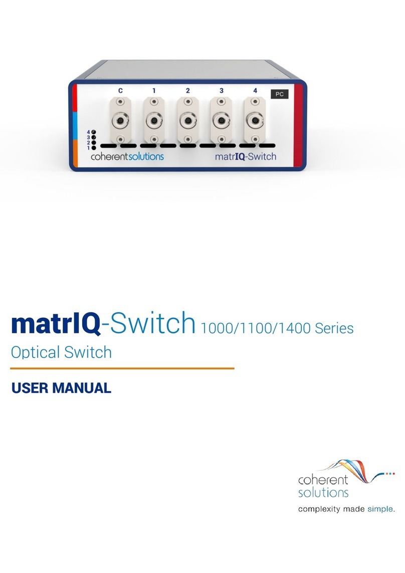
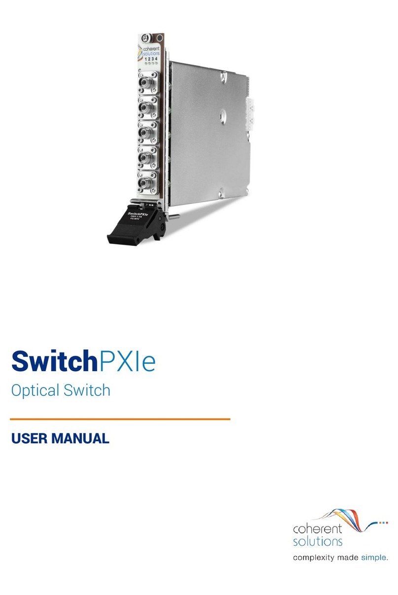
Coherent Solutions SwitchBlade User manual


Modular Optical Switch |SwitchBlade
i
Copyright © 2017 Coherent Solutions Ltd. All rights reserved. No part of this publication may be reproduced,
stored in a retrieval system or transmitted in any form, be it electronically, mechanically, or by any other
means such as photocopying, recording or otherwise, without the prior written permission of Coherent
Solutions Ltd. (Coherent Solutions).
Information provided by Coherent Solutions is believed to be accurate and reliable.
However, no responsibility is assumed by Coherent Solutions for its use nor for any infringements of patents or
other rights of third parties that may result from its use. No license is granted by implication or otherwise
under any patent rights of Coherent Solutions.
The information contained in this publication is subject to change without notice.
Trademarks
Coherent Solutions’ trademarks have been identified as such. However, the presence or absence of such
identification does not affect the legal status of any trademark.
Units of Measurement
Units of measurement in this publication conform to SI standards and practices.
Version Number: V1.4

Modular Optical Switch |SwitchBlade
ii
Contents
1Conventions ............................................................................................................ 1
2Safety Information................................................................................................... 2
3Introducing the SwitchBlade –Modular Optical Switch ............................................ 3
4SwitchBlade Features .............................................................................................. 5
5MTP1000 Features................................................................................................... 6
6Connecting Optical Output....................................................................................... 7
6.1 Cleaning and Connecting Optical Fibers................................................................................................ 7
7Installing a SwitchBlade Expansion Module.............................................................. 8
8Removing a SwitchBlade Expansion Module .......................................................... 11
9Installing the Software........................................................................................... 14
9.1 Client System Minimum Requirements .............................................................................................. 14
9.2 Test Instrument Manager Software Installation ................................................................................. 14
10 Test Instrument Manager Software........................................................................ 15
10.1 Test Instrument Manager Interface .................................................................................................... 15
10.2 Device Selection .................................................................................................................................. 15
10.3 Main Display........................................................................................................................................ 16
10.4 Switch Selection Control ..................................................................................................................... 17
10.5 Routing Control ................................................................................................................................... 17
10.6 Fiber Type Display ............................................................................................................................... 17
10.7 Other Menu Buttons ........................................................................................................................... 18
11 Programming Guide............................................................................................... 21
11.1 Programming Conventions.................................................................................................................. 21
11.2 Common Command Summary ............................................................................................................ 22
11.3 Common Command Descriptions ....................................................................................................... 22
11.4 Specific Command Summary .............................................................................................................. 23
11.5 Specific Command Descriptions.......................................................................................................... 23
11.5.1 Slot Commands........................................................................................................................... 23
11.5.2 Configuration Commands........................................................................................................... 24
11.6 2x2 SwitchBlade (Crossover) ............................................................................................................... 25
11.7 VISA Programming Example: MATLAB ................................................................................................ 26
11.8 MATLAB Test and Measurement Tool (tmtool)............................................................................... 26
11.9 MATLAB Example Code: Query the MTP1000..................................................................................... 28
12 USB Connection Web Interface .............................................................................. 29
12.1 Network Configuration (Ethernet) ...................................................................................................... 29
12.2 Download Log File ............................................................................................................................... 30
13 Maintenance ......................................................................................................... 31

Modular Optical Switch |SwitchBlade
iii
14 Technical Support .................................................................................................. 33
14.1 Contacting the Technical Support Group ............................................................................................ 33
14.2 Transportation .................................................................................................................................... 33
15 Warranty............................................................................................................... 34
15.1 General Information............................................................................................................................ 34
15.2 Liability ................................................................................................................................................ 34
15.3 Exclusions ............................................................................................................................................ 34
15.4 Certification......................................................................................................................................... 35
15.5 Service and Repairs ............................................................................................................................. 35

Modular Optical Switch |SwitchBlade
Coherent Solutions |SwitchBlade (V1.4) 1
1Conventions
Before using the instrument described in this manual, you should understand the following conventions:
WARNING
Indicates a potentially hazardous situation which, if not avoided, could result in
death or serious injury. Do not proceed unless you understand and meet the
required conditions.
CAUTION
Indicates a potentially hazardous situation which, if not avoided, may result in
minor or moderate injury. Do not proceed unless you understand and meet the
required conditions.
CAUTION
Indicates a potentially hazardous situation which, if not avoided, may result in
component damage. Do not proceed unless you understand and meet the required
conditions.
IMPORTANT
Refers to information about this product you should not overlook.

Modular Optical Switch |SwitchBlade
Coherent Solutions |SwitchBlade (V1.4) 2
2Safety Information
WARNING
Do not install or terminate fibers while a light source is active. Care
must be taken to ensure that the instrument has been turned OFF
before inspecting the end face(s) of the instrument, or any optical
patch cords connected to this instrument. Never look directly into a live
fiber and ensure that your eyes are protected at all times.
The use of controls, adjustments and procedures other than those
specified herein may result in exposure to hazardous situations or
impair the protection provided by this unit.
CAUTION
The SwitchBlade expansion modules are sensitive to electrostatic
discharge (ESD). Please be sure to store the modules that are not
installed in protective electrostatic packaging.
IMPORTANT
For electromagnetic compatibility, this instrument is a Class A product. It is
intended for use in an industrial environment. There may be potential
difficulties in ensuring electromagnetic compatibility in other environments,
due to conducted as well as radiated disturbances.
When you see the following symbol on your unit , make sure that you
refer to the instructions provided in your user documentation. Ensure that you
understand and meet the required conditions before using your product.

Modular Optical Switch |SwitchBlade
Coherent Solutions |SwitchBlade (V1.4) 3
3Introducing the SwitchBlade –Modular Optical Switch
The SwitchBlade –Modular Optical Switch is an efficient solution for test procedure automation designed to
be used in the MTP1000 platform. The MEMS based optical switch ensures repeatable and low-loss switching
to various test set-ups while taking advantage of the MTP1000 mainframe’s flexible connectivity and high
channel density form-factor, SwitchBlade easily becomes an integral part of your test set-up.
The modular chassis design of the MTP1000, with nine (9) expansion slots, can hold up to thirty-six (36) optical
switches providing great flexibility to manage the number of switches to meet changing laboratory demands.
Figure 2 - Coherent Solutions MTP1000 Modular Platform with different Blades
Figure 1 - Coherent Solutions SwitchBlade - Modular Optical Switch

Modular Optical Switch |SwitchBlade
Coherent Solutions |SwitchBlade (V1.4) 4
All MTP1000 mainframes connected to the
network can be managed remotely from a
single client using the simple and intuitive
‘Test Instrument Manager’software
interface.
Alternatively, VISA programming
environments such as MATLAB can also be
implemented to integrate with existing test
software or data collection procedures.
Figure 3 - Test Instrument Manager Software

Modular Optical Switch |SwitchBlade
Coherent Solutions |SwitchBlade (V1.4) 5
4SwitchBlade Features
1. Optical Switch Ports*
2. Release latch
*Note: Optical Switch Ports are specific to each model of SwitchBlade. The example shown is a 1x4
model SwitchBlade.

Modular Optical Switch |SwitchBlade
Coherent Solutions |SwitchBlade (V1.4) 6
5MTP1000 Features
MTP1000 Front Panel
3. Power On/Off
4. USB 2.0 Connection
5. Ethernet Connection
6. Laser Interlock (Output Enable/Disable)
7. Blade Expansion Slots (9 Bays)
MTP1000 Back Panel
8. Thermal Regulation Fans (6)
9. Mains Power Isolation Switch
10. AC Power 100-240V, 50-60Hz

Modular Optical Switch |SwitchBlade
Coherent Solutions |SwitchBlade (V1.4) 7
6Connecting Optical Output
IMPORTANT
To ensure maximum power and to avoid erroneous readings always inspect
fiber ends and make sure that they are clean as explained below before
inserting them into the port. Coherent Solutions is not responsible for
damage or errors caused by bad fiber cleaning or handling.
CAUTION
The type of optical connectors on the MTP1000 is specific to the
SwitchBlade modules installed. This information can be found printed on
the front plate of the SwitchBlade module and in the separate Spec sheet
provided. Joining mismatched connectors will damage the ferrules.
6.1 Cleaning and Connecting Optical Fibers
To connect the fiber-optic cable to the port:
1. Inspect the fiber using a fiber inspection microscope. If the fiber is clean, proceed to connecting it to the
port. If the fiber is dirty, clean it as explained below.
2. Clean the fiber ends as follows:
2a. Gently wipe the fiber end with a lint-free swab dipped in isopropyl alcohol.
2b. Use compressed air to dry completely.
2c. Visually inspect the fiber end to ensure its cleanliness.
3. Carefully align the connector and port to prevent the fiber end from touching the outside of the port or
rubbing against other surfaces. If your connector features a key, ensure that it is fully fitted into the port’s
corresponding notch.
4. Push the connector in so that the fiber-optic cable is firmly in place, thus ensuring adequate contact. If
your connector features a screw sleeve, tighten the connector enough to firmly maintain the fiber in place.
Do not over tighten, as this will damage the fiber and the port.
Note: If your fiber-optic cable is not properly aligned and/or connected, you will notice heavy loss and reflection.
Coherent Solutions uses good quality connectors in compliance with EIA-455-21A standards.
To keep connectors clean and in good condition, Coherent Solutions strongly recommends inspecting them
with a fiber inspection probe before connecting them. Failure to do so will result in permanent damage to the
connectors and degradation in measurements.

Modular Optical Switch |SwitchBlade
Coherent Solutions |SwitchBlade (V1.4) 8
7Installing a SwitchBlade Expansion Module
WARNING
DO NOT attempt to remove or adjust any component of the MTP1000 while the
power is on. Make sure you follow the correct procedures below and power down
the MTP1000 first.
CAUTION
Do not remove the SwitchBlade from the antistatic packaging until instructed
during the following installation procedure.
The SwitchBlade is sensitive to ESD. Please be sure to wear a grounded wrist
strap at all times when handling the SwitchBlade module to prevent such
damage.
Take care not to handle the connector on the SwitchBlade module once they
are exposed as this may leave corrosive residue which can damage the
connector.
Note: You will need a Phillips and Slot screwdriver to both unfasten the blanking module and secure the new
SwitchBlade module in place.
Power down the MTP1000
1. Press the Power On/Off switch. The switch will
no longer be illuminated indicating that the
instrument is off.
Figure 4 - Turn Off Power
Remove the blanking module
2. To remove the blanking module of the desired
slot, loosen the captive screws on the top and
bottom of the blanking module. Do not attempt
to remove the screws completely as they are
designed to stay inside the front plate of the
module.
Figure 5 - Unfasten screw under Release Latch

Modular Optical Switch |SwitchBlade
Coherent Solutions |SwitchBlade (V1.4) 9
3. Slide the blanking module out to remove it and
store the blanking module near the
MTP1000 for future use.
Figure 6 - Remove Blanking Module
Remove the SwitchBlade from packaging
4. Unpack the SwitchBlade module from the
antistatic packaging, making sure to store the
packaging near the MTP1000 so it is available to
safely store any SwitchBlade that may be
removed in the future.
Figure 7 - Remove and store Antistatic Packaging
Insert the SwitchBlade securing into place
5. Slide the SwitchBlade into the available slot using
the guide rails.
6. Once the SwitchBlade reaches the connector at
the end of the slot, press your thumbs on the
release latch and the top of the SwitchBlade
module as shown in Figure 10 to make sure the
SwitchBlade seats correctly.
Figure 9 - Install the SwitchBlade Module
Figure 10 - Press the SwitchBlade Module to seat it into the
Connector
Figure 8 - MTP1000 and SwitchBlade Guide Rails

Modular Optical Switch |SwitchBlade
Coherent Solutions |SwitchBlade (V1.4) 10
7. Once the SwitchBlade is installed, fasten the
screw in the release latch to lock the SwitchBlade
into place.
Figure 11 - Fasten screw in Release Latch
Power on the MTP1000
8. Power on the MTP1000 by pressing the
Power On/Off switch. The switch will
become illuminated to verify that the
instrument is powered on.
Figure 12 - Power On the MTP1000
IMPORTANT
After powering on the MTP1000, please wait at least 2 minutes before
attempting to communicate with the instrument. This will allow the
MTP1000 enough time to finish boot procedures and initialize the
communication server.
The new SwitchBlade is now ready for use.
9. Use your preferred method of communicating
with the MTP1000 to use the newly installed
SwitchBlade.
Figure 13 - TIM software

Modular Optical Switch |SwitchBlade
Coherent Solutions |SwitchBlade (V1.4) 11
8Removing a SwitchBlade Expansion Module
WARNING
DO NOT attempt to remove or adjust any component of the MTP1000 while the
power is on. Make sure you follow the correct procedures below and power down
the MTP1000 first.
CAUTION
The SwitchBlade is sensitive to ESD. Please be sure to wear a grounded wrist
strap at all times when handling the SwitchBlade module to prevent such
damage.
Take care not to handle the connector on the SwitchBlade module once they
are exposed as this may leave corrosive residue which can damage the
connector.
IMPORTANT
A Blanking module will be required to replace the removed SwitchBlade
module. Please make sure you have a blanking module available. The
specifications of the SwitchBlade are only valid when all empty slots have
blanking modules.
You will need antistatic packaging to store the SwitchBlade upon removal at
the appropriate step in the following installation procedures. Please make sure
this packaging is immediately available before continuing with the following
procedure.
Note: You will need a Phillips and Slot screwdriver to both unfasten the SwitchBlade module and secure the
blanking module in place.
Acquire storage electrostatic packaging and blanking module
1. In preparation for removal of the SwitchBlade module, locate and retrieve the antistatic packaging the
SwitchBlade was supplied in. This should have been stored near the MTP1000 when the SwitchBlade was
installed.
2. Also you will require a blanking module to install once the SwitchBlade has been removed.
IMPORTANT
Do not continue unless you have the blanking module and appropriate
storage packaging for the removed SwitchBlade. If the SwitchBlade is not
stored correctly it may be affected by ESD. The specifications of the
SwitchBlade are only valid when all slots have blanking modules.

Modular Optical Switch |SwitchBlade
Coherent Solutions |SwitchBlade (V1.4) 12
Power down the MTP1000
3. Press the Power On/Off switch. The
switch will no longer be illuminated
indicating that the instrument is off.
Figure 14 - Turn Off Power
WARNING
Take care when handling the SwitchBlade as during operation the
SwitchBlade module may be very hot.
Remove the SwitchBlade
4. To remove the desired SwitchBlade module,
loosen the screw underneath the release latch.
Do not try to remove the screw completely as
they are designed to stay inside the release
latch.
Figure 15 - Unfasten screw under Release Latch
5. Press downward on the release latch to unseat
the SwitchBlade module from the back
connector as shown in Figure 16.
Figure 16 - Press down on the Release Latch
6. Slide the SwitchBlade module out to remove.
Figure 17 - Slide out the SwitchBlade Module

Modular Optical Switch |SwitchBlade
Coherent Solutions |SwitchBlade (V1.4) 13
Package the SwitchBlade for storage
7. Once removed, put the SwitchBlade module
into the antistatic packaging for storage. This
will ensure the SwitchBlade is not subject to
ESD.
Figure 18 - Store the SwitchBlade Module
8. Slide the blanking module into the empty slot
using the guide rails.
Figure 19 - Install the Blanking Module
9. Once the blanking module is fully inserted,
fasten the captive screws on the top and
bottom of the blanking module to secure it into
place.
Figure 20 - Fasten screw under Release Latch
Power on the MTP1000
10. Power on the MTP1000 by pressing the Power
On/Off switch. The switch will become
illuminated to verify that the instrument is
powered on.
Figure 21 - Power on the MTP1000
IMPORTANT
After powering on the MTP1000, please wait at least 2 minutes before
attempting to communicate with the instrument. This will allow the MTP1000
enough time to finish boot procedures and initialize the communication server.

Modular Optical Switch |SwitchBlade
Coherent Solutions |SwitchBlade (V1.4) 14
9Installing the Software
IMPORTANT
Make sure the client PC is connected to the same network as the
MTP1000 and the MTP1000 is also powered on before proceeding with
software installation.
TIM version 2.2 or later is required to manage an MTP1000 with a
SwitchBlade module.
9.1 Client System Minimum Requirements
Operating System
Windows 7 or later
Minimum Screen Resolution
800x600
Free Hard Disk Space
1GB
Communication Port
USB 2.0 (Ethernet and USB 2.0 recommended)
9.2 Test Instrument Manager Software Installation
Begin the installation by running the ‘CSTIMSetup.[version].exe’’ file located on the supplied media. This will
start the installation of the Test Instrument Manager software package.
1. When the installation begins, you will see the Welcome screen. Click on Next to begin the installation.
2. Please read the license agreement. If you choose to accept the agreement, click on the “I accept the terms
of the License Agreement”check box and then click "Install". If you do not wish to accept the terms of the
agreement, click on "Cancel" to terminate the software installation.
3. Once the license agreement has been accepted the installation will begin and the file progress will be
displayed throughout the installation.
4. When the installation has completed you can click on "Finish" with the check box ticked (by default) to
immediately start the Test Instrument Manager software.
5. The installer will also place a Test Instrument Manager application shortcut on your desktop.

Modular Optical Switch |SwitchBlade
Coherent Solutions |SwitchBlade (V1.4) 15
10 Test Instrument Manager Software
Home page
When the Test Instrument Manager is run, the Home
page is displayed. The devices on the network
automatically show up.
Click and drag the desired MTP1000 devices from
‘Discovered Instruments’ to the ‘Monitored
Instruments’ list to enable management of these
devices, this opens the main Test Instrument
Manager interface.
Figure 22 - Test Instrument Manager Start-up Device
Select
Note: If there are no devices listed in the ‘Discovered Instruments’ list, refer to section ‘Refresh’ for instruction
on how to detect your MTP1000 devices.
10.1 Test Instrument Manager Interface
1. Device Selection
2. Main Display
3. Switch Selection
Control
4. Routing Control
5. Fiber Type Display
6. Other Menu Buttons
Note: The Switch Selection
Control (3) and Fiber Type
Display (5) are not
populated until a selection
of switches has been made,
see below.
Figure 23 - Test Instrument Manager Interface
10.2 Device Selection
The Device Selection menu lists all the devices that were selected for management in the Device
Instruments interface.
Click the drop-down box and select the desired device to be the currently managed unit. This unit will now be
shown in the Main Display.
2
3
4
5
6
1
6

Modular Optical Switch |SwitchBlade
Coherent Solutions |SwitchBlade (V1.4) 16
10.3 Main Display
The Main Display is the primary information panel of the software interface. It displays the MTP1000 device
and all the installed modules in a format that simulates the configuration of the actual device.
1. SwitchBlade Module
2. Optical Switch
Switch source information:
Channel number
Port SET position
Port ACTUAL position
Port State Symbol
(: No route to port, : Current routed port)
Figure 24 - Main Display
To view information for a single switch at a
glance, hover the mouse pointer over the switch
and a pop-up information window will appear (as
seen in
Figure 25).
This pop-up window will display the channel
number, port number and status.
Figure 25 - Switch Information Pop-up
1
2
Table of contents
Other Coherent Solutions Switch manuals