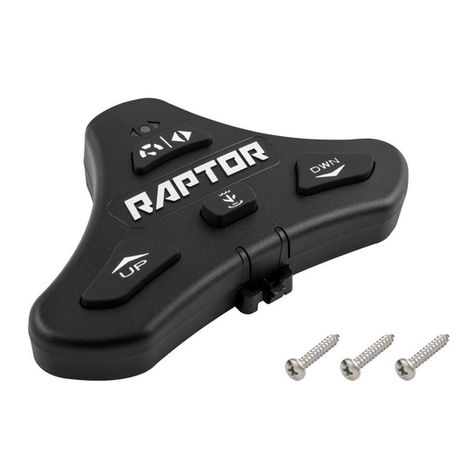
MINN KOTA TALON User manual

FOOT SWITCH
Owner's Manual
Compatible with all Bluetooth®enabled Talons.

2 | minnkotamotors.com ©2018 Johnson Outdoors Marine Electronics, Inc.
INTRODUCTION
SER NO S365 MK12345
EXAMPLE
NOTICE: The serial number on your Talon Foot Switch is
located on the reverse side of the switch from the buttons.
If the Foot Switch is attached to the Pedestal, remove the
Foot Switch from the Pedestal to see the serial number.
THANK YOU
Thank you for purchasing the Talon Foot Switch. Intuitive features and wireless control lets you easily raise and lower the Talon spike.
Control up to two Talons – independently or simultaneously – from this Bluetooth®enabled waterproof switch. Hands free control lets
you focus on fishing.
Model:__________________________________________________________________________________________________________________
Serial Number: __________________________________________________________________________________________________________
Purchase Date: __________________________________________________________________________________________________________
Store Where Purchased:___________________________________________________________________________________________________
REGISTRATION
Remember to keep your receipt and immediately register your
Talon Foot Switch. To receive all the benefits of your product
warranty please fill out and mail the registration card. You may
also register your product online at minnkotamotors.com.
SERIAL NUMBER
Your Minn Kota 11-character serial number is very important. It
helps to determine the specific model and year of manufacture.
When contacting Consumer Service or registering your product,
you will need to know your product’s serial number. We
recommend that you write the serial number down so that you
have it available for future reference.
NOTICE: Do not return your Talon Foot Switch to your retailer. Your retailer is not authorized to repair or replace this unit. You
may obtain service by calling Minn Kota at (800) 227-6433 or returning your Talon Foot Switch to the Minn Kota Factory Service
Center. Please include proof of purchase, serial number and purchase date for warranty service.
TALON FOOT SWITCH INFORMATION (For Consumer Reference Only)

minnkotamotors.com | 3
©2018 Johnson Outdoors Marine Electronics, Inc.
SAFETY CONSIDERATIONS
Please thoroughly read the user manual. Follow all instructions and heed all safety considerations. Use of this product is only permitted
for persons that have read and understood these instructions. Minors may use this product only under adult supervision.
WARNING
You are responsible for the safe and prudent operation of your boat or vessel, and Talon(s). This product does not relieve you from the
responsibility of safe operation of your boat. It may be hazardous to operate your Talon in rough or turbulent water conditions, such
as fast currents or changing environmental conditions. Do not deploy your Talon if these conditions are present, especially when the
underwater topography is unknown. Failure to follow this warning may result in unexpected operation or failure of the Talon to operate
or anchor and could cause death or serious injury. You must avoid hazards to anchoring and always maintain a permanent watch so you
can maintain proper control of your boat. You must always be prepared to regain manual control of your boat. Learn to operate your
Minn Kota product in an area free from hazards and obstacles.
WARNING
The Talon should be disconnected from the power source when it is not in use or is off the water. Always disconnect the Talon from
battery(s) before cleaning or checking the Talon. In the event of unexpected operation, remove power leads from the battery.
WARNING
Take care that neither you nor other persons approach the Talon Spike too closely while operating, neither with body parts nor with
objects. The Talon is powerful and may endanger or injure you or others. While the Talon is operating, watch out for persons swimming
and for floating objects. Persons who lack the ability to run the Talon or whose reactions are impaired by alcohol, drugs, medication, or
other substances are not permitted to use this product.
WARNING
It is recommended to only use Johnson Outdoors approved accessories with your Talon. Using non-approved accessories including
those used to mount or control your product may cause damage, unexpected operation and injury. Be sure to use the product and
all approved accessories, including remotes, safely and in the manner directed to avoid accidental or unexpected operation. Keep
all factory installed parts in place including motor, electronic and accessory covers, enclosures and guards. Failure to adhere to this
warning may affect your warranty.
CAUTION
Never leave the boat unattended with the Talon as your only boat anchor. Talon is not intended to provide primary anchorage.

4 | minnkotamotors.com ©2018 Johnson Outdoors Marine Electronics, Inc.
FEATURES
NOTE: Specifications subject to change without notice. This diagram is for reference only and may differ from your
actual Foot Switch.
Auto Down
Button/Pairing
Button
Auto Up Button/
Pairing Button Anchor
Mode Button
Talon Selection Button /
Work Light Button
Talon Selection Indicator LEDs
Anchor Mode
Selection LED

minnkotamotors.com | 5
©2018 Johnson Outdoors Marine Electronics, Inc.
INSTALLATION
INSTALLING THE TALON FOOT SWITCH
Your new Talon Foot Switch comes complete with all of the hardware you’ll need to install it directly to the deck of your boat. Please
review the parts list, mounting considerations and tools needed for installation prior to getting started.
INSTALLATION PARTS LIST
Item /
Assembly Part # Description Qty.
A2994153 ASSEMBLY, TALON 3 FT SWITCH 1
22383455 SCREW-#8 X 1.0" PPH TY AB SS 3
4sQUICK REFERENCE GUIDE 1
6sINSTALLATION INSTRUCTIONS 1
✖This part is included in an assembly and cannot be ordered individually.
sNot shown on Parts Diagram.
A
Before mounting your Talon Foot Switch, please give consideration to the following:
1. Examine your boat to ensure that you will not drill into any obstructions and that the hardware will be accessible for assembly.
2. Make sure the area under the mounting location is flat, clear to drill holes and that the installation hardware will not damage
existing components below the mounting surface. It may be necessary to shim or modify the mounting surface under the mounting
location to create a flat area for the Foot Switch Pedestal to be mounted.
3. Mount the Talon Foot Switch in an area that has a clear line of communication with the Bluetooth enabled Talon(s) it is intended to
control for optimum performance.
4. Mount the Talon Foot Switch in an area where it will not become a tripping hazard.
MOUNTING CONSIDERATIONS
2
• Pencil or similar marking tool
• Drill
• #2 Phillips Driving Bit
TOOLS AND RESOURCES REQUIRED

6 | minnkotamotors.com ©2018 Johnson Outdoors Marine Electronics, Inc.
INSTALLING THE FOOT SWITCH
Installing the Foot Switch
a. Review the Mounting Considerations to determine
an acceptable mounting location. Once a location
is selected, take the Talon Foot Switch Assembly
(Item #A) and remove the Pedestal from the Base by
squeezing the Tabs on both sides of the Foot Pedal
and pulling the Foot Switch and Pedestal apart.
1
2
ITEM(S) NEEDED
#A x 1
NOTICE: The Pedestal comes attached to
the Foot Switch and needs to be removed for
installation.
Foot Switch
Pedestal
Marked Location
Mounting Holes
Pads
Pedestal (top)
Pedestal (bottom)
Tab
Tab
INSTALLATION
b. The Pedestal has three Mounting Holes that are
used to secure it to the boat. The bottom side of the
Pedestal has three Pads around the Mounting Holes.
These Pads should be placed down, towards the boat
when the Pedestal is installed. Position the Pedestal
at the selected location and mark the Mounting
Holes with a pencil or similar marking tool.

minnkotamotors.com | 7
©2018 Johnson Outdoors Marine Electronics, Inc.
INSTALLING THE FOOT SWITCH
4
3
Mounting Holes
Pedestal
d. Once the Pedestal is installed, take the Foot Switch
and reattach it to the Pedestal. Make sure the Tabs
on the Foot Switch click into place and the Foot
Switch is fully seated on the Deck of the Boat.
c. Double check the Mounting Location. Take the
Screws (Item #2) and place one each in the
Mounting Holes of the Pedestal. Make sure the
Mounting Holes line up with the Marked Locations
and then use a Drill with #2 Phillips Driving Bit to
secure the Pedestal to the Deck of the Boat. Do not
over-tighten.
ITEM(S) NEEDED
#2 x 3
Deck of Boat
Deck of Boat
Screws Pedestal
Tab
Foot
Switch
Tab

8 | minnkotamotors.com ©2018 Johnson Outdoors Marine Electronics, Inc.
INSTALLING THE FOOT SWITCH
a. Retract the anchor on the Talon by pressing the Up
button on the Talon Indicator Panel.
b. Once the Talon is fully retracted, press and hold the
Up button and the Down button on the Foot
Switch at the same time until all of the LED's at the
top of the Foot Switch begin to scroll. Then release
them.
c. Immediately press and hold the Up button
and the Down button simultaneously on the
Indicator Panel. The Depth Indication LEDs on the
Indicator Panel of the Talon will begin to scroll. Once
the LEDs are scrolling release the buttons on the
Indicator Panel. The Talon and Foot Switch will go
into Pairing Mode for 20 seconds. If a signal with
three fast beeps occurs, the Talon and Foot Switch
have successfully paired. If 20 seconds pass while
in Pairing Mode and they do not successfully pair, an
error tone will sound indicating that the pairing was
not successful, and the Foot Switch will not be able
to control the Talon.
d. If the Pair is unsuccessful, repeat the process.
Up Button
Down Button Indicator
Panel
11a
Talon Foot Switch
Auto Down
Button/Pairing
Button
Auto Up Button/
Pairing Button
Anchor Mode
Selection LED
Talon Selection
Indicator LEDs
Pairing a Foot Switch to a Single Talon
In order to Pair a Foot Switch to the Talon, please be sure to first
Pair the Talons together. When two Bluetooth Talons are paired
together, the Foot Switch that was paired to an individual Talon
will operate both Talons. Please see the "Pairing Two Talons and
Programming the Mounting Location" section of the Talon Owner's
Manual. If the two Talons are already paired together, a Foot Switch can be paired to either Talon. When the pairing process is
complete, the Foot Switch will be able to control both Talons.
Pairing a Foot Switch to Two Talons
NOTICE: For instructions on how to pair two Talons and
assign their Port and/or Starboard mounting locations,
please refer to your Talon owners manual.

minnkotamotors.com | 9
©2018 Johnson Outdoors Marine Electronics, Inc.
USING THE FOOT SWITCH
Anchor Mode Button
Used to select between Standard Mode, Soft
Bottom Mode and Rough Water Mode.
Auto Up/Auto Down Buttons
& Pairing Buttons
Used to deploy, retract or pause the anchor on the
Talon. Also used to pair the Remote to a Talon.
Talon Selection Button /
Work Light Button
Used to select the Port, Starboard, or both Talons.
Used to toggle the Work Light "on" and "off" and
switch between the different Work Light colors and
intensities.
Talon Selection Indicator LEDs
When 2 Talons are paired in the system, the right
LED is lit when the Starboard Talon is selected and
the left LED is lit when the Port Talon is selected.
Both the right and left arrows are lit when both
Talons are selected. When only one Talon is paired,
the lights will toggle, but the selection will control
the only paired Talon. When a selection is made, the
LEDs will stay lit for 1 second and then turn off.
Anchor Mode Selection LED
The Center LED flashes red and green and then turns
off for Standard Mode. The center LED will be lit
green for Soft Bottom Mode and lit red for Rough
Water Mode. When in Soft Bottom Mode and Rough
Water Mode, the LED will stay lit for 1 second and
then turn off.
Auto Down
Button/Pairing
Button
Auto Up Button/
Pairing Button
Anchor
Mode Button Talon Selection Button/
Work Light Button
Talon Selection Indicator LEDs
Anchor Mode
Selection LED
CONTROLLING THE TALON WITH THE FOOT SWITCH

10 | minnkotamotors.com ©2018 Johnson Outdoors Marine Electronics, Inc.
USING THE FOOT SWITCH
The Talon Selection button toggles the Talon that the Foot Switch is controlling, when 2 Talons are installed on the boat. The
selection toggles between a Talon mounted on the Port or Starboard side of the boat, or it can control both Talons at the same time.
The Talon Selection Indicator LED's are lit based on the selection made.
a. To toggle the Talon selected, press the Talon
Selection button, repeatedly until the desired
Talon is selected.
b. When the button is pressed, one or both of the
Talon Selection Indicator LEDs will be lit. If the
Foot Switch is oriented so the LEDs are facing away
from you, the arrow on the right will be lit when the
Starboard Talon is selected. If the arrow on the left is
lit, the Port Talon is selected. If both arrows are lit,
both Talons are selected.
Selecting a Talon to Operate with the Foot Switch
NOTICE: The Talon will always remember the last
selection made unless the Talon loses power.
NOTICE: When two Talons are paired to the Foot
Switch, it is possible to control them individually.
Therefore, the Talons may be in different states of
deployment.
Talon
Selection
Button
Talon Selection
Indicator LEDs
Talon Foot Switch
Port Starboard
1

minnkotamotors.com | 11
©2018 Johnson Outdoors Marine Electronics, Inc.
USING THE FOOT SWITCH
Deploy the Talon from the Foot Switch
Use the buttons on the Foot Switch to deploy the Talon anchor.
a. To deploy the Talon, double press the Down
button on the Foot Switch.
b. While the anchor is deploying, the action can be
paused on the Foot Switch by pressing either the
Down button or Up button again.
c. The paused deployment can be resumed by double
pressing the Down button again.
d. Once the deploying anchor gets to its full length of
travel or comes in contact with the bottom, it will go
through an anchoring sequence determined by the
current Mode and then stop.
NOTICE: When two Talons are paired, the anchor
of the selected Talon will deploy. The selection can
be Port, Starboard, or both.
NOTICE: You do not need to hold the button to keep
the Talon deploying. The Talon will automatically continue
to deploy when the button is double pressed until it has
reached its full deployment, received input to stop or
anchors to the bottom.
1
WARNING
Take care that neither you nor other persons approach the Talon too closely, while operating, neither with body parts nor with
objects. The Talon is powerful and may endanger or injure you or others. While the Talon is operating, watch out for persons
swimming and for floating objects. Persons who lack the ability to run the Talon or whose reactions are impaired by alcohol, drugs,
medication, or other substances are not permitted to use this product.
Talon Foot Switch
Auto Down
Button/Pairing
Button
Auto Up Button/
Pairing Button

12 | minnkotamotors.com ©2018 Johnson Outdoors Marine Electronics, Inc.
USING THE FOOT SWITCH
Use the buttons on the Foot Switch to retract the Talon anchor.
a. To retract the Talon, press the Up button on the
Foot Switch.
b. While the anchor is retracting, the action can be
paused on the Foot Switch by pressing either the Up
button or the Down button.
c. The paused retraction can be resumed by pressing
the Up button again.
d. Once the retracting anchor on the Talon gets to its
full retraction it will stop. If the Talon is already fully
retracted and the Up button is pressed again, an
error tone will sound.
NOTICE: When two Talons are paired, the anchor
of the Talon selected on the Foot Switch will
retract. The selection can be Port, Starboard, or
both.
NOTICE: You do not need to press and hold the button
to keep the anchor retracting. The Talon will automatically
continue to retract when the button is pressed until the
Talon is either fully retracted or receives input to stop.
Retracting the Talon from the Foot Switch
CAUTION
Be sure that the Talon is clear of obstructions and persons
while retracting. The spaces between the 3 stages of the Talons
can create a pinch point. Do not come in contact with the Talon
while it is retracting to avoid the pinch point.
1
Talon Foot Switch
Auto Down
Button/Pairing
Button
Auto Up Button/
Pairing Button

minnkotamotors.com | 13
©2018 Johnson Outdoors Marine Electronics, Inc.
USING THE FOOT SWITCH
NOTICE: When the Talon is paired with a second
Talon, pressing the Anchor Mode button on the
Talon will toggle the Mode for both Talons.
Toggle the Mode on the Foot Switch when the water or anchoring conditions change to fit your anchoring needs.
a. The Mode can be toggled from the Foot Switch by
selecting the Anchor Mode button. The Anchor
Mode Selection LED displays the Mode that the
Talon is currently set to. Press the Anchor Mode
button to toggle to the desired Mode.
b. When the Talon is put in Standard mode, the LED
will flash red and green and then turn off. When the
LED is Green, the Talon is in Soft Bottom Mode.
When the LED is Red, the Talon is in Rough Water
Mode.
Toggle the Mode from the Foot Switch
Anchor Mode
Selection LED
The Work Light at the top of the Talon can be either white or blue and toggled between high, medium, or low intensities.
a. To Toggle the Work Light "on", press and hold the
Talon Selection button until the Work Light on
the top of the Talon turns "on".
b. Continue to press the Talon Selection button on
the Foot Switch again before 5 seconds passes until
the desired color and intensity is selected.
c. To toggle the Work Light "off" press and hold the
Talon Selection button again until the Work Light
turns "off".
Control the Work Light with the Foot Switch
NOTICE: When the Talon is paired with a second
Talon, pressing and holding the Talon Selection
button will toggle the light for both Talons. The six
intensities for the Work Light are white high, white
medium, white low, blue high, blue medium and
blue low.
1
1
WARNING
The Work Light on the Talon is not intended for navigational
purposes. The Work Light does not replace or act as a
substitute for proper navigation lighting of your vessel. Failure
to properly light your boat may cause harm or serious injury.
Talon Foot Switch
Anchor
Mode Button
Talon Foot Switch
Talon Selection Button/
Work Light Button

14 | minnkotamotors.com ©2018 Johnson Outdoors Marine Electronics, Inc.
SERVICE & MAINTENANCE
a. Make sure your hands are clean, dry and static free.
Temporarily ground yourself by touching a grounded
metal object in order to discharge any static
electricity in your body. Foot
Switch
Back
Battery
Cover
b. With the back of the Foot Switch facing you,
use a large coin to rotate the Battery Cover
counterclockwise until the Battery Cover loosens and
cannot be turned any further counterclockwise.
REPLACING THE REMOTE BATTERY
CAUTION
Before beginning any maintenance work, disconnect the Talon from the battery or if connected to a battery selector switch or power
disconnect switch, make sure that it is turned to the "off" position. Failure to disconnect power during maintenance work may result in
shock, unexpected operation and/or injury. Minn Kota recommends having the Talon serviced by an qualified marine technician at an
Authorized Service Center.
• Large Coin
TOOLS AND RESOURCES REQUIRED
INSTALLATION
1b
1
CAUTION
Static electricity can cause damage to the circuit board.
Discharge any static electricity by touching a metal object
that is grounded before beginning the remote battery
replacement.
NOTICE: The battery for the Foot Switch may be
replaced with, or without the Pedestal attached.

minnkotamotors.com | 15
©2018 Johnson Outdoors Marine Electronics, Inc.
REPLACING THE REMOTE BATTERY
NOTICE: The replacement battery must be
a model CR2450 coin cell type. It is strongly
recommended that a high quality battery is used.
The positive (+) of the battery should be facing
towards the Battery Cover.
c. Remove the Battery Cover and the old battery.
Replace the battery with a new CR2450 coin cell
battery. Note the proper polarity of the battery.
Foot Switch Back
Battery
Cover
Battery
O-ring
d. Ensure the rubber O-ring is properly seated in the
underside of the Battery Cover.
e. Replace the Battery Cover by aligning either of the
Unlock icons with the Tabs, and pressing the cover
down.
f. Rotate the Battery Cover clockwise using the large
coin until the Lock Icon aligns with the Tabs.
Foot Switch
Battery
Cover
Tab
Tab Lock Icon
Lock Icon
Align
Tab
Tab
Foot Switch
O-ring
Unlock
Icon
Unlock
Icon
Battery
Cover
Battery
2
3
3d
3e

16 | minnkotamotors.com ©2018 Johnson Outdoors Marine Electronics, Inc.
PAIRING A FOOT SWITCH TO A SINGLE TALON
CLEARING PAIRED TALONS FROM THE FOOT SWITCH
a. Press and hold the Up button and the Down
button on the Foot Switch at the same time until all
of the LED's at the top of the Foot Switch begin to
scroll. Then release the buttons. The Foot Switch will
go into Pairing Mode for 20 seconds. Once Pairing
times out all Talons will be cleared.
The Foot Switch was designed so that all paired Talons can be cleared from memory.
1
NOTICE: Putting the Foot Switch into Pairing
Mode, even if it is accidental, without Pairing the
Foot Switch to a Talon will clear all paired Talons. Talon Foot Switch
Auto Down
Button/Pairing
Button
Auto Up Button/
Pairing Button
Talon Selection
Indicator LEDs
Anchor Mode
Selection LED

minnkotamotors.com | 17
©2018 Johnson Outdoors Marine Electronics, Inc.
TROUBLESHOOTING AND REPAIR
We offer several options to help you troubleshoot and/or repair your product. Please read through the options listed below.
Buy Parts Online
You can buy parts on-line directly from our website at minnkotamotors.com. Orders confirmed by 12 Noon Central Time, with
Overnight Shipping selected, should ship the same business day if the parts are in stock. All other orders should ship within the
next 3 business days, depending on the shipment method chosen, and if the parts are in stock.
Frequently Asked Questions
We have FAQs available on our website to help answer all of your Minn Kota questions. Visit minnkotamotors.com and click on
“Frequently Asked Questions” to find an answer to your question.
Call Us (for U.S. and Canada)
Our consumer service representatives are available Monday – Friday between 7:00 a.m. – 4:30 p.m. CST at 800-227-6433. If you
are calling to order parts, please have the 11-character serial number from your product, specific part numbers, and credit card
information available. This will help expedite your call and allow us to provide you with the best consumer service possible. You can
reference the parts list located in your manual to identify the specific part numbers.
Email Us
You can email our consumer service department with questions regarding your Minn Kota products. To email your question, visit
minnkotamotors.com and click on “Support”.
Authorized Service Centers
Minn Kota has over 800 authorized service providers in the
United States and Canada where you can purchase parts or
get your products repaired. Please visit our Authorized
Service Center page on our website to locate a service
provider in your area.
Scan to visit Minn
Kota service online.
NOTICE: There are no serviceable components inside
the Talon Foot Switch.

18 | minnkotamotors.com ©2018 Johnson Outdoors Marine Electronics, Inc.
COMpLIANCE STATEMENTS
REGULATORY COMPLIANCE INFORMATION
Talon Foot Switch
FOOT SWITCH : 2994153
• Contains IC: 5123A-BGTBLE121LR
• Contains FCC ID: QOQBLE121LR
ENVIRONMENTAL COMPLIANCE STATEMENT
It is the intention of JOME to be a responsible corporate citizen, operating in compliance with known and applicable environmental
regulations, and a good neighbor in the communities where we make or sell our products.
WEEE DIRECTIVE
EU Directive 2002/96/EC “Waste of Electrical and Electronic Equipment Directive (WEEE)” impacts most distributors, sellers, and
manufacturers of consumer electronics in the European Union. The WEEE Directive requires the producer of consumer electronics to
take responsibility for the management of waste from their products to achieve environmentally responsible disposal during the product
life cycle.
WEEE compliance may not be required in your location for electrical & electronic equipment (EEE), nor may it be required for EEE
designed and intended as fixed or temporary installation in transportation vehicles such as automobiles, aircraft, and boats. In some
European Union member states, these vehicles are considered outside of the scope of the Directive, and EEE for those
applications can be considered excluded from the WEEE Directive requirement.
This symbol (WEEE wheelie bin) on product indicates the product must not be disposed of with other household
refuse. It must be disposed of and collected for recycling and recovery of waste EEE. Johnson Outdoors Inc. will mark
all EEE products in accordance with the WEEE Directive. It is our goal to comply in the collection, treatment, recovery,
and environmentally sound disposal of those products; however, these requirements do vary within European Union
member states. For more information about where you should dispose of your waste equipment for recycling and
recovery and/or your European Union member state requirements, please contact your dealer or distributor from which
your product was purchased.
DISPOSAL
Minn Kota Talons are not subject to the disposal regulations EAG-VO (electric devices directive) that implements the WEEE directive.
Nevertheless never dispose of your Minn Kota Talon in a garbage bin but at the proper place of collection of your local town council.
Never dispose of battery in a garbage bin. Comply with the disposal directions of the manufacturer or his representative and dispose of
them at the proper place of collection of your local town council.

minnkotamotors.com | 19
©2018 Johnson Outdoors Marine Electronics, Inc.
COMPLIANCE STATEMENTS
ENVIRONMENTAL RATINGS
Ambient operating temperature range: -10C to 50C
Ambient operating humidity range: 5% to 95%
Maximum operating altitude: 10,000 feet
CE MASTER USER MANUAL (FOR CE CERTIFIED MODELS)
TRADEMARKS
Minn Kota®, i-Pilot® and i-Pilot® Link™ are trademarked by or
registered trademarks of Johnson Outdoors Marine Electronics,
Inc.
The Bluetooth® word mark and logos are registered trademarks
owned by Bluetooth SIG, Inc. and any use of such marks by
Johnson Outdoors Inc is under license. Other trademarks and
trade names are those of their respective owners.
RADIO OPERATION
CONTROLLER
• Frequency band: 2402 MHz to 2480 MHz
• Maximum RF power transmitted: +10 dBm
FOOT SWITCH
• Frequency band: 2402 MHz to 2480 MHz
• Maximum RF power transmitted: +10 dBm
FCC COMPLIANCE
This device complies with Part 15 of the FCC rules. Operation is subject to the following two conditions:
1. This device may not cause harmful interference.
2. This device must accept any interference that may be received, including interference that may cause undesired operation.
Changes or modifications not expressly approved by Johnson Outdoors Marine Electronics, Inc. could void the user’s authority to
operate this equipment.
INDUSTRY CANADA COMPLIANCE
This product meets the applicable Industry Canada technical specifications. Operation is subject to the following two conditions:
(1) this device may not cause interference, and (2) this device must accept any interference, including interference that may cause
undesired operation of the device.
Changes or modifications not expressly approved by Johnson Outdoors Marine Electronics, Inc. could void the user’s authority to
operate this equipment.
NOTICE: This equipment has been tested and found to comply with the limits for a Class B digital device, pursuant to part
15 of the FCC Rules. These limits are designed to provide reasonable protection against harmful interference in a residential
installation. This equipment generates, uses and can radiate radio frequency energy and, if not installed and used in accordance
with the instructions, may cause harmful interference to radio communications. However, there is no guarantee that interference
will not occur in a particular installation. If this equipment does cause harmful interference to radio or television reception, which
can be determined by turning the equipment off and on, the user is encouraged to try to correct the interference by one or more of the
following measures:
• Reorient or relocate the receiving antenna.
• Increase the separation between the equipment and receiver.
• Connect the equipment into an outlet on a circuit different from that to which the receiver is connected.
• Consult the dealer or an experienced radio/TV technician for help.

20 | minnkotamotors.com ©2018 Johnson Outdoors Marine Electronics, Inc.
pARTS DIAGRAM & pARTS LIST
Talon Foot Switch Parts Diagram
TALON FOOT SWITCH
The parts diagram and parts list provides Minn Kota® WEEE compliance disassembly instructions. For more information about where
you should dispose of your waste equipment for recycling and recovery and/or your European Union member state requirements, please
contact your dealer or distributor from which your product was purchased. Tools required, but not limited to: flat head screwdriver,
Phillips screwdriver, socket set, pliers, wire cutters.
22
14
8
10
6
2
12
24
20
26
4
18
16
A
28
B
Other manuals for TALON
7
Table of contents
Languages:
Other MINN KOTA Switch manuals
Popular Switch manuals by other brands

Kobold
Kobold LNZ operating instructions

Giga-tronics
Giga-tronics ASCOR Series 8000 Getting started guide

Austin Hughes Electronics
Austin Hughes Electronics CyberView N117 series Catalog

Lantronix
Lantronix SISPM1040 L3 Series install guide

KTI
KTI KS-1080 installation guide

PROCET
PROCET PT-PIS4PB1S-M Quick installation guide