OIL AND FUEL
Engine Oil
Mini bike may have oil in it when
shipped from the factory.
However, it is a good idea to
drain this oil and replace with
new SAE 10W-30 Motor Oil.
1
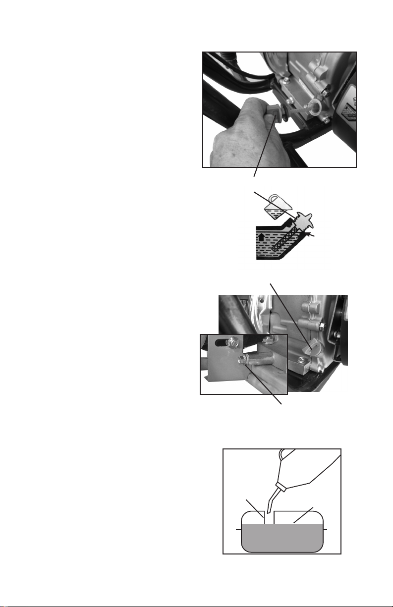
Changing the engine oil
1. Remove the oil ll plug (1)
2. Remove the drain bolt (2) located on
the bottom of the engine.
3. Allow the oil to drain in an appropriate
container. Note: Dispose of oil at an oil
recycle center.
4. Install the drain plug and ll with SAE
10W-30 motor oil. This mini bike takes
.63qt. (.6L) of engine oil. Oil should be up
to the brim of the ll hole.
5. Re- install ll cap, Start engine and
allow to run for a few minutes, Re-check
oil level and ll accordingly.
1
2
Fuel level
Filler neck
FUEL
Never use leaded gasoline in this product.
It could affect the engine’s emissions and
damage the engine.
Mini Bike requires clean unleaded regular
gasoline with a minimum octane rating of
86 or higher.
Fill with gasoline up to the bottom of the
ller neck.
6
Caution: Do not over or under ll
with Motor Oil
Fill level


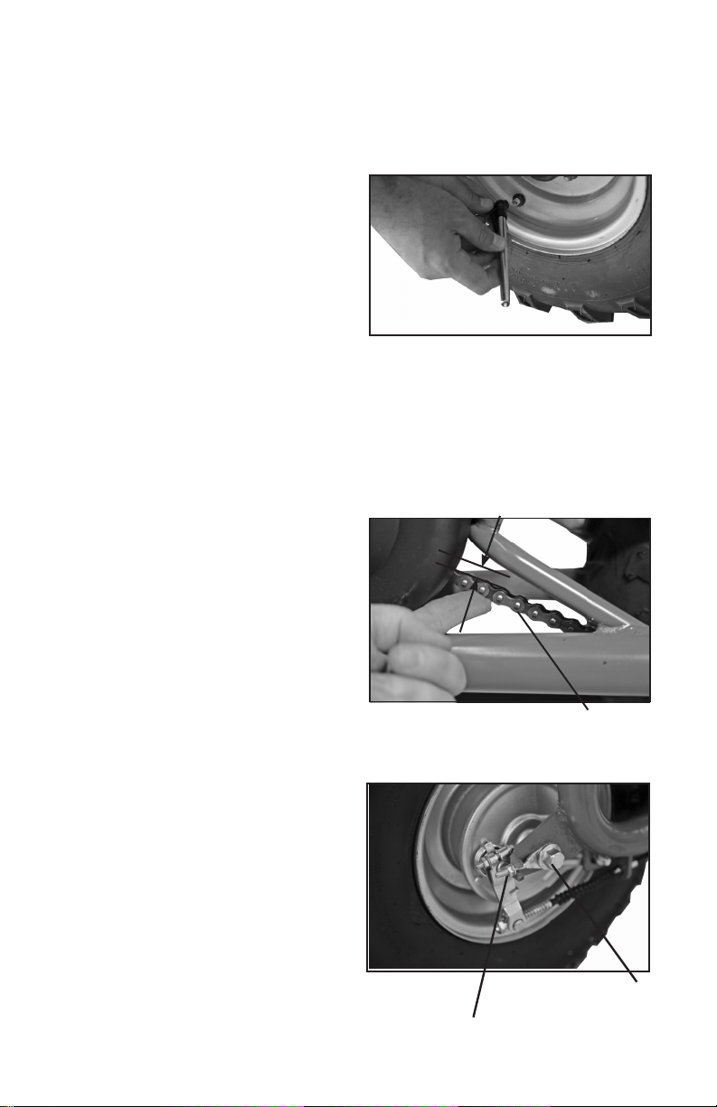
 Supplementary service manual")