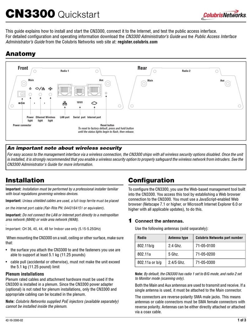
Colubris Networks MARP-330r User manual

1 of 6
42-11-0330-09
MAP-330R Quickstart
This guide shows you how to set up a MAP-330R MultiService Access Point.
For detailed configuration and operating information see
the MAP-300 Series Administrator’s Guide, which is availa
ble on the Colubris Networks documentation CD or at www.colubris.com
(select Support and then Product Registration).
NOTE: The MAP-330R is a ruggedized version of the MAP-330 and shares the same feature set. However, due to its weather-proof
enclosure, Ethernet port 2 and the reset button are not available. When using the management tool, ignore references to port 2. For units
purchased after March 1, 2006, see the Administrator’s Guide for instructions on how to reset to factory default settings.
IMPORTANT NOTE ABOUT WIRELESS SECURITY: To provide easy wireless access to the management interface, the MAP-330R ships
with all wireless security options disabled. Colubris strongly recommends that once the MAP-330R is installed you enable a wireless
security option to properly safeguard the wireless network from intruders. For more information see the Administrator’s Guide.
Hardware overview
Package contents
• MAP-330R unit featuring die-cast aluminum enclosure with
three-point silicone rubber gasket.
• Two 5.5-dBi 2.4-GHz omnidirectional antennas. These antennas
support 802.11b and 802.11g modes only. They do not support
802.11a.
• Weather-proof quick-disconnect RJ45 connector (disassembled).
• Standard mounting bracket.
• Pole-top mounting assembly.
• Documentation CD.
Antennas
The MAP-330R has two radios, each with one antenna connector. Each
radio can create a single wireless cell or be used as an Integrated Sensor
as described on page 6. The antenna connectors are weather-proof
straight-polarity N-type female bulkhead antenna connectors with
diversity
Note: By default radio 1 is set to b/g mode, and radio 2 is set to Monitor.
Ethernet port
The MAP-330R has a single 10/100 Mbps Ethernet port with weather-
proof RJ45 connector. Power over Ethernet (PoE) is used to power the
MAP-330R on this port.
Ethernet port with PoE support
and a weather-proof connector
MAP-330R sealed in
weather-proof enclosure
Radio 1 Radio 2
Opening enclosure voids warranty.
Pole-top mounting assembly Standard mounting bracket
Weather-proof quick-disconnect
(shown assembled)
RJ45 connector

2 of 6 42-11-0330-09
Typical deployment
Attaching an Ethernet cable
To provide a weather-proof seal, the Ethernet port on the MAP-330R uses a custom weather-proof cable connector. You must terminate your Ethernet
cable with this connector as described in the following procedure. Make sure that you use ruggedized, shielded, outdoor-rated category 5 Ethernet
cable. Cable length should not exceed 300 feet (100 meters).
1. Carefully unpack the nine quick-disconnect items from the plastic
bag, identifying all parts as illustrated. If any parts are missing, DO
NOT proceed until you get a replacement parts kit.
2. If your Cat 5 Ethernet cable already has an RJ45 connector on the
end that will connect to the Colubris equipment, remove the RJ45
connector by cutting the cable at least half an inch (1.2 cm) before
the RJ45 connector.
Be sure to make a clean cut with a pair of sharp angle cutters. The
complete cut (through both the cable sheath and all wires) must
occur in a single cutting motion.
3. Hold Clamp Ring (C) horizontally, with its fingers to the left. Insert
the Seal (B) into the fingers on the left end so that it is flush with the
end of the fingers. Insert the Gasket (D) into the right end, pushing it
against the ridge at the end of the threads. The Gasket is beveled on
one side. The beveled side should face inwards away from the Screw
Nut.
4. Thread the Sealing Nut (A) onto the left end of the Clamp Ring (C).
Tighten it only enough for it to stay attached.
5. Hold the Screw Nut (E) vertically, with the open threads facing up,
and drop the Body (f) into it, with the RJ45 connector opening facing
up.
6. Hold the Clamp Ring (C) vertically below the Screw Nut/Body items
and screw the Body into the threads on the Clamp Ring (C). Tighten
it only enough to stay attached. Note that the Screw Nut (E) remains
loose on the Body (F).
7. Remove the white backing paper from one of the RJ45 Gaskets (H)
and press the glued side onto the Body (F) being very careful to
align the gasket with the RJ45 connector shape on the Body (F).
8. Remove the backing paper from the second RJ45 Gasket (H) and
press it over the first one, being sure to maintain alignment.
9. Tighten the threads between Body (F) and Clamp Ring (C) by hand.
DO NOT tighten between Clamp Ring (C) and Sealing
Ring (A). Do not over tighten. Do not tighten with tools.
The quick-disconnect assembly should now look like this when held
horizontally, with the Sealing Nut (A) at the left end, and the Screw
Nut (E) over the Body (F) at the right end.
W
L
A
N
Broadband
Modem
MultiService Controller
Colubris Networks
Injector
PoE Switch
Hub/
I
n a typ
i
ca
l
i
nsta
ll
at
i
on t
h
e
MAP
-
330R
i
s mounte
d
out
d
oors
(in a salt-free environment), providing a wireless cell. It is
connected to a PoE injector (not supplied) and then to a hub
or switch that connects it to a Colubris Networks MultiService
Controller.
Important
• The MAP-330R must always be mounted with its
antennas pointing up.
• Do not connect the Ethernet port directly to a
metropolitan area network (MAN) or wide area
network (WAN).
Radio 2Radio 1
Sealing
Nut Seal Clamp
Ring Screw
Nut
RJ45
Plug
Gasket Body RJ45
Gaskets
AB CDE F GH
Weatherproof connector parts

3 of 6
42-11-0330-09
10.Carefully thread the cleanly-cut end of the Cat 5 Ethernet cable
through the Sealing Nut (A) end of the quick-disconnect assembly,
and push through approximately 1 foot (30 cm) of cable.
Note: The next two steps should be performed by someone with
experience building Ethernet cables.
11.Prepare the cable and attach it to the RJ45 Plug (G) according to the
directions included with your crimping tool.
12.Before continuing, test the cable with a portable Ethernet cable tester
to ensure that the RJ45 plug (G) is correctly connected.
13.Carefully pull the cable slack back through the quick-disconnect
assembly until the RJ45 Plug (G) is almost touching the Body (F).
Adjust the cable position so that the RJ45 Plug (G) fits precisely into
the RJ45 cutout in the Body (F), and press down the plastic tab so
the plug fits correctly.
14.Tighten the threads between Sealing Nut (A) and Clamp Ring (C) by
hand, until the cable is firmly anchored. Do not over tighten. Do
not tighten with tools.
15.Mate the RJ45 Plug (G) with the socket on the Colubris Networks
equipment, hold it firmly in place, and tighten the Screw Nut (E) by
hand. Do not over tighten. Do not tighten with tools.
Creating a drip loop
A drip loop provides additional protection against water running down the
Ethernet cable and into the connector. Form the loop as shown in the
diagram. Make sure that the distance between the loop start and end
points is at least 6 inches (15 cm), and that the cable hangs down at least
10 inches (25 cm).
Lightning and electrical
discharge protection
Colubris Networks recommends the following best practices for installing
the MAP-330R in an area that is lightning-prone or subject to high
electrical discharge. Compliance with these guidelines can help reduce
the potential for damage from atmospheric static discharge during
electrical storms. No protection against damage caused by static
discharge or a direct lightning strike is implied and/or covered under
warranty.
• Ensure that the MAP-330R is well grounded, in accordance with the
NFPA 70 National Electrical Code and any pertinent local codes.
• Use a shielded Ethernet cable to connect to the MAP-330R.
• If possible, ensure that a properly grounded lightning rod or other
static dissipation device is placed higher than the MAP-330R.
• Attach lightning surge suppressors to each MAP-330R antenna post.
• When a long outdoor run of Ethernet cable is used, maximum length
300 feet (100 meters), install an Ethernet surge suppressor as close
as possible to the MAP-330R—ideally within 2 feet (.5 meters). This
helps reduce the effects of any charge carried by the cable to the
MAP-330R.
The following third-party products (available at www.hyperlinktech.com)
or their equivalents are compatible with the MAP-330R.
•Antenna surge suppressor: N-Male to N-Female Bulkhead 0-6 GHz
Coaxial Lightning Surge Protector, part number AL6-NMNFB-9.
•PoE lightning protector: Weather-proof PoE compatible
10/100 base-T CAT5 lightning protector, part number AL-CAT5W.
Note: Colubris Networks does not guarantee or warrant third-party
products.
Drip loop
10 inches
6 inches
(15 cm)
(25 cm)

4 of 6 42-11-0330-09
Controlled and Autonomous modes
The MAP-330R supports two modes of operation: controlled mode and autonomous mode.
Controlled mode
Controlled mode is the default operating mode for the MAP-330R when
shipped with 5.1 firmware and higher. It lets you take advantage of
centralized management and plug-and-play installation.
When operating in controlled mode:
• The MAP-330R must be installed in conjunction with an MSC-5000
series service controller.
• The MAP-330R’s management tool will not allow local configuration
changes. The MAP-330R must be configured and managed through
the service controller’s management tool. For more information see
the MSC-5000 Series Administrator’s Guide.
Autonomous mode
In autonomous mode, the MAP-330R operates as an independently
managed access point, just as in software releases prior to 5.1.
This means:
• The MAP-330R is managed and configured locally.
• Centralized management and monitoring via an MSC-5000 series
service controller are not available.
Important: If you upgrade a MAP-330R from a software release prior to 5.1, it
starts up in autonomous mode.
Controlled MAP-330R initial configuration
When operating in controlled mode, initial configuration of the MAP-330R is not required. Simply power it up and connect it to a network that provides
access to an MSC-5000 series service controller. Once the MAP-330R connects with the service controller, its firmware and configuration settings will
be updated if required.
Note: A MAP-330R operating in controlled mode must obtain its IP address from a DHCP server. Ensure that a DHCP server is available on the
network, or that an MSC is configured to operate as a DHCP server. To configure an MSC to act as a DHCP server, on the MSC in the left pane select
Service Controller,and then in the right pane select Network > Address allocation.
To power-up the MAP-330R, connect an 802.3af PoE power source. The MAP-330R is fully operational when the power light stops flashing.

5 of 6
42-11-0330-09
Autonomous MAP-330R initial configuration
For initial configuration of an autonomous MAP-330R you use the built-in
web-based management tool to perform the following steps. Access this
tool by establishing a web browser connection to the MAP-330R.
Supported web browsers are Microsoft Internet Explorer 6.0 or higher
and Mozilla Firefox 1.5 or higher.
1Power-on the MAP-330R
Connect a PoE source (not supplied) to the MAP-330R.
2Connect your computer
a. Use a crossover cable (not supplied) to connect the LAN port on
your computer to the PoE source.
b. Configure your computer with the static IP address
192.168.1.2.
3Start the Management Tool
a. Open a Web browser and in the address bar specify
https://192.168.1.1. Press Enter.
b. When prompted to accept a Colubris Networks security
certificate, do so in order to continue.
c. The MAP-330R Login page opens. Specify admin for both
Username and Password, and then click Login.
4The first time you log in, you are prompted to do the
following:
a. Switch to Autonomous mode. If the following warning
appears on the Welcome page, at bottom click
Switch to Autonomous Mode.
Switching modes reboots the MAP-330R and resets all
configuration settings to factory defaults. Before you can
continue, you must log in again.
b. Accept the end user license agreement. Read the agreement and
then click Accept License Agreement. You must quit the
application if you do not agree.
c. Configure the country where the MAP-330R is installed. Select
the appropriate Country from the list and click Save.
d. Change the default administrator password. Enter a new
password and click Save.
5Configure the wireless network
By default the MAP-330R is configured to automatically select the
best operating channel (frequency) and to create a wireless network
named Colubris Networks. There is no need to change these settings
for this initial configuration.
6Configure the MAP-330R
a. Select VSC > Profiles and click the Colubris Networks
profile. The Add/Edit Virtual Service Community page
opens.
• To install the MAP-330R as a stand-alone device that is not
connected to an access controller, clear the Wireless security
filters checkbox.
• To install a MAP-330R that connects to a Colubris Networks
access controller, under General, select the Use Colubris
access controller checkbox.
b. By default the MAP-330R operates as a DHCP client to obtain its
IP address. In this configuration the MAP-330R’s serial number
can be used to manage the device. If static IP addressing is
preferred, select Network > Ports, and then click
Bridge port in the list. Select Static and then click Configure.
The MAP-330R is now ready for operation
For additional configuration and operating information, see the
MAP-300 Series Administrator’s Guide.

6 of 6 42-11-0330-09
Initial configuration of the optional Integrated Sensor
In addition to its access point features, the MAP-330R can function as an
RF sensor on one or both of its radios for use in conjunction with a
Colubris Networks RF Manager server.
The MAP-330R Integrated Sensor is implemented by installing an
optional license. The Sensor is disabled if no valid license is installed.
• If you purchased the Integrated Sensor license at the same time that
you purchased your MAP-330R, the license is factory-installed. You
do not need to worry about installing a license.
• If you purchased the Integrated Sensor license upgrade after you
purchased the MAP-330R, you must install the license file.
• For an autonomous mode MAP-330R, select Maintenance >
Licensing. For more information see the MAP-300 Series
Administrator’s Guide.
• For a controlled mode MAP-330R, the license is installed and
managed using the service controller’s management tool. For
more information see the MSC-5000 Series Administrator’s
Guide.
Use the following steps to enable and configure the Integrated Sensor.
1Start the Management Tool
• For an autonomous MAP-330R, start the MAP-330R’s
management tool as described on page 5.
• For a controlled MAP-330R, start the management tool on the
associated MSC-5000 series service controller.
2Configure the sensor to connect to an RF Manager
server
a. Open the Sensor configuration page.
• For an autonomous MAP-330R, select Security > Sensor.
• For a controlled MAP-330R, in the left pane under Main Menu,
expand the Service Controller, Controlled APs, and
Default Group nodes, and then select the name of the
MAP-330R (By default, this will be the MAP’s serial number.). In
the right pane select Configuration > Sensor. Clear the
Inherited checkbox.
b. Under Connect to RF Manager Server using,
• Select Server ID and then enter the ID number of the RF
Manager Server with which to connect. Enter 0to specify that the
MAP-330R search for the first available RF Manager Server.
Support for multicast traffic must be enabled on all routers and
switches between the MAP-330R and the RF Manager Server.
• Select IP address and hostname to connect to a specific RF
Manager Server, then enter the IP address of the RF Manager
Server or its hostname. If you enter a hostname, ensure that the
MAP-330R is able to resolve the hostname through DNS. An
entry must be created on the network DNS server that points to
the IP address of the RF Manager Server.
c. Click Save.
3Connect to the network
Connect the MAP-330R to a network that provides access to an RF
Manager Server.
• The MAP-330R must be able to reach the RF Manager Server
through a network connected to port 1. You should be able to ping
the RF Manager Server's IP address from the MAP-330R.
• If there are any firewalls between the MAP-330R and the RF
Manager Server, TCP and UDP ports 3851 must be open in both
directions.
The Integrated Sensor is now operational
and should be detected by the RF Manager
server.
© 2006 Colubris Networks, Inc. Specifications are subject to change without notice. Colubris is a registered trademark, and the Colubris logo is a trademark,
of Colubris Networks, Inc. All other names mentioned herein are trademarks or registered trademarks of their respective owners. Printed in the USA.
Table of contents
Other Colubris Networks Wireless Access Point manuals
Popular Wireless Access Point manuals by other brands

D-Link
D-Link D DWL-8200AP DWL-8200AP user manual

D-Link
D-Link DWL-6610AP Quick installation guide

SOMFY
SOMFY myLink quick start guide

D-Link
D-Link DWL-2700AP - AirPremier Outdoor Wireless Access... user manual

ZyXEL Communications
ZyXEL Communications NWA-3165 Declaration of conformity

araknis
araknis AN-100-AP-I-N product manual