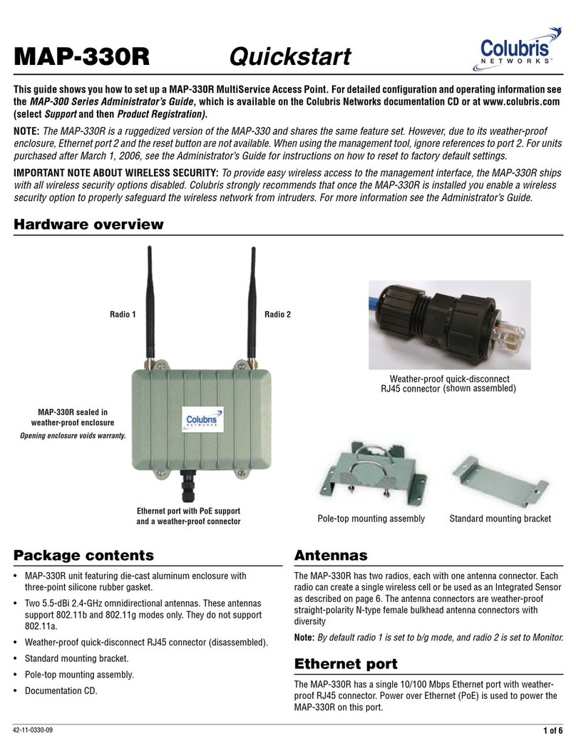
Colubris Networks 5000 series User manual

Colubris Networks
Configuration Guide

Release 5.1 (October 2006) 43-10-0000-02
Copyright © 2006 Colubris Networks, Inc. All rights reserved, including those to
reproduce this document or parts thereof in any form without written permission from
Colubris Networks, Inc.
Colubris is a registered trademark, and the Colubris Networks logo, the tag line “The
Intelligent Wireless Networking Choice” and TriPlane are trademarks of Colubris
Networks, Inc., in the United States and other countries.
All other product and brand names are the service marks, trademarks, registered
trademarks, or registered service marks of their respective owners.
Changes are periodically made to the information herein; these changes will be
incorporated into new editions of the document.
You can download the most up-to-date product information from the Colubris Networks
website. Go to www.colubris.com and on the homepage at left select Support >
Product Registration.
Colubris Networks, Inc.
200 West Street Ste 300
Waltham, Massachusetts 02451-1121
UNITED STATES
Phone: +1 781 684 0001
Fax: +1 781 684 0009
Sales Information—[email protected]
Customer Support—suppor[email protected]
Training—tr[email protected]
http://www.colubris.com

- - - - - - - - - - - - - - - - - - - - - - - - - - - - - - - - - - - - - - - - - - - - - - - - -Contents - - - - - - - - - - - - - - - - - - - - - - - - - - - - - - - - - - - - - - - - - - - - - - - - -
- - - - - - - - - - - - - - - - - - - - - - - - - - - - - - - - - - - - - - - - - - - - - - - - - - - - 3 - - - - - - - - - - - - - - - - - - - - - - - - - - - - - - - - - - - - - - - - - - - - - - - - - - - -
Contents
Chapter 1
Introduction 5
About this guide...........................................................................................6
Chapter 2
Management 9
Remote management.................................................................................10
Chapter 3
Public access deployment - 3000 series 13
Scenario 1a: Hotspot with Internet access (local config) ...........................14
Scenario 1b: Hotspot with custom interface (local config) ........................17
Scenario 1c: Hotspot with satellites and roaming (local config) ................20
Scenario 1d: Hotspot with layer 2 security (local config)...........................23
Scenario 2a: Hotspot with Internet access (AAA server)............................26
Scenario 2b: Hotspot with custom interface (AAA server) .........................30
Scenario 2c: Hotspot with satellites and roaming (AAA server) .................33
Scenario 2d: Hotspot with layer 2 security (AAA server) ...........................36
Scenario 2e: Using dual radios to support A+B+G traffic ...........................40
Scenario 3: Shared hotspot for public and private traffic ...........................41
Scenario 4: Delivering custom HTML pages using VLANs.........................45
Scenario 5: Custom HTML pages on each MAP.........................................50
Scenario 6: Multi-site installation (distributed architecture).......................54
Scenario 7: Multi-site installation (centralized architecture).......................58
Chapter 4
Public access deployment - 5000 series 61
Scenario 1a: Hotspot with satellites and roaming (local config) ................62
Scenario 1b: Hotspot with custom interface (local config) ........................65
Scenario 1c: Hotspot with layer 2 security (local config) ...........................67
Scenario 2a: Hotspot with satellites and roaming (AAA server) .................70
Scenario 2b: Hotspot with custom interface (AAA server) .........................74
Scenario 2c: Hotspot with layer 2 security (AAA server)............................76
Scenario 2d: Using dual radios to support A+B+G traffic...........................79
Scenario 3: Shared hotspot for public and private traffic ...........................81
Scenario 4: Delivering custom HTML pages using VLANs.........................86
Scenario 5: Custom HTML pages on each MAP.........................................91
Scenario 6: Multi-site installation (centralized architecture).......................95
Chapter 5
Enterprise deployment 99
Scenario 1: Adding secure wireless networking.......................................100
Scenario 2a: Integrating wireless networking with authentication............102
Scenario 2b: Using multiple wireless profiles and QoS............................104
Scenario 2c: Supporting wireless phones................................................106
Scenario 3: Adding wireless networking to a segmented network ...........108
Scenario 4: Roaming across different subnets (single MSC) ...................112
Scenario 5: Roaming across different subnets (multiple MSCs)..............115
Scenario 6: Private and public access networks in the enterprise............117
Chapter 6
WDS scenarios 125
Wireless bridging considerations.............................................................126
Scenario 1: RF extension to expand a wired network (static)...................127
Scenario 2: Deploying a point-to-point wireless link (static)....................131
Scenario 3: Setting up multi-hop wireless links (static)...........................137
Scenario 4a: Basic dynamic WDS deployment (3000 series)...................141
Scenario 4b: Basic dynamic WDS deployment (5000 series) ..................147
Scenario 4c: Dynamic WDS links with load balancing .............................153
Scenario 5: Creating a self-healing network .............................................155
Chapter 7
Configuring DHCP servers to use Colubris vendor classes
161
Windows Server 2003 .............................................................................162
ISC DHCP server......................................................................................166
Troubleshooting.......................................................................................168
Chapter 8
Configuring a legal intercept 171
Redirecting traffic into a GRE tunnel........................................................172
Limiting NAT port range and tracking activity in the syslog .....................180
Chapter 9
More from Colubris 181
Colubris.com ...........................................................................................182
Information by telephone and e-mail .......................................................183

- - - - - - - - - - - - - - - - - - - - - - - - - - - - - - - - - - - - - - - - - - - - - - - - -Contents - - - - - - - - - - - - - - - - - - - - - - - - - - - - - - - - - - - - - - - - - - - - - - - - -
- - - - - - - - - - - - - - - - - - - - - - - - - - - - - - - - - - - - - - - - - - - - - - - - - - - - 4 - - - - - - - - - - - - - - - - - - - - - - - - - - - - - - - - - - - - - - - - - - - - - - - - - - - -

Introduction
Chapter 1
Introduction
In this chapter you can find an explanation of the conventions used in
this guide and an overview of its contents.

Chapter 1 - - - - - - - - - - - - - - - - - - - - - - - - - - - - - - - - - - - - - - - - Introduction- - - - - - - - - - - - - - - - - - - - - - - - - - - - - - - - - - - - - - - - - Chapter 1
- - - - - - - - - - - - - - - - - - - - - - - - - - - - - - - - - - - - - - - - - - - - - - - - - - - - 6 - - - - - - - - - - - - - - - - - - - - - - - - - - - - - - - - - - - - - - - - - - - - - - - - - - - -
About this guide
This guide contains detailed scenarios for using Colubris®Networks MultiService
Access Points (MAPs) and MultiService Controllers (MSCs) in a wide range of
applications.
Although detailed configuration steps are provided for each scenario, the guide does not
cover the basic procedures for operating and configuring Colubris Networks devices.
This information can be found in the administrator’s guides. You should be familiar with
this information before you attempt to use the scenarios in this guide.
The scenarios are grouped according to function.
Typographical
conventions
The following table gives the typographical conventions used in Colubris Networks
technical documentation.
Warnings,
cautions, and
notes
The following table explains some of the special symbols used in this guide.
Example Description
Network > Ports When referring to the Management Tool web
interface, bold type identifies menu selections,
input fields, or user supplied values. Submenus
are indicated by the > sign. The example refers
to the Ports submenu, which is found under
the Network menu.
use-access-list=username Monospaced text identifies command-line
output, program listings, or commands that you
enter into configuration files or profiles.
ip_address Items in italics are parameters for which you
must supply a value.
ssl-certificate=URL [%s] Items enclosed in square brackets are optional.
You can either include them or not. Do not
include the brackets.
[ONE | TWO] Items separated by a vertical line indicates one
or more choices. Specify only one of the items.
Lead Description
Warning! Warnings provide information that you must follow to avoid risk of
physical injury.
Caution! Cautions provide information that you must follow to avoid
damage to the hardware or software components of the system.

Chapter 1 - - - - - - - - - - - - - - - - - - - - - - - - - - - - - - - - - - - - - - - - Introduction- - - - - - - - - - - - - - - - - - - - - - - - - - - - - - - - - - - - - - - - - Chapter 1
- - - - - - - - - - - - - - - - - - - - - - - - - - - - - - - - - - - - - - - - - - - - - - - - - - - - 7 - - - - - - - - - - - - - - - - - - - - - - - - - - - - - - - - - - - - - - - - - - - - - - - - - - - -
Acronyms The following table defines acronyms used in this guide.
Related
documentation
For information on related documentation, see the Colubris Networks Te c h n i c a l
Documentation Road Map, available on the Colubris Networks Documentation CD and
for download on the Colubris Networks web site.
Software
versions
For information on using Colubris Netwokrs products with different software revisions,
see the Software Compatibility Matrix available on the Colubris Networks
Documentation CD and for download on the Colubris Networks web site.
Acronym Definition
CIMS Colubris Intelligent Mobility System
CNMS Colubris Networks Management System
COS Colubris Operating System
DWDS Dynamic wireless distribution system
MAP MultiService Access Point
MSC MultiService Controller
VSC Virtual service community
WCB Wireless client bridge
WDS Wireless distribution system

Chapter 1 - - - - - - - - - - - - - - - - - - - - - - - - - - - - - - - - - - - - - - - - Introduction- - - - - - - - - - - - - - - - - - - - - - - - - - - - - - - - - - - - - - - - - Chapter 1
- - - - - - - - - - - - - - - - - - - - - - - - - - - - - - - - - - - - - - - - - - - - - - - - - - - - 8 - - - - - - - - - - - - - - - - - - - - - - - - - - - - - - - - - - - - - - - - - - - - - - - - - - - -

Management
Chapter 2
Management
This chapter presents strategies for managing one or more devices
across various network topologies.

Chapter 2 - - - - - - - - - - - - - - - - - - - - - - - - - - - - - - - - - - - - - - - - Management - - - - - - - - - - - - - - - - - - - - - - - - - - - - - - - - - - - - - - - - Chapter 2
- - - - - - - - - - - - - - - - - - - - - - - - - - - - - - - - - - - - - - - - - - - - - - - - - - - - 10 - - - - - - - - - - - - - - - - - - - - - - - - - - - - - - - - - - - - - - - - - - - - - - - - - - - -
Remote management
Note: When using a series 5000 MSC in conjunction with MAPs operating in controlled
mode all MAP configuration is handled via the management tool on the MSC. Therefore,
remote management does not need to be configured as described in this section.
When a MAP is installed behind an MSC, enabling remote access to its management
tool requires configuration settings to be defined on the MSC and the RADIUS server.
This section explains how to configure remote management for the following two
topologies.
• In topology A, the management tool is located behind a router and on a different
network segment.
• In topology B, the management station is located at a remote site. Access occurs via
the Internet using a VPN tunnel to safeguard the traffic.
192.168.10.0
192.168.1.0
192.168.20.0
192.168.1.0
30.2
30.1
30.3
10.1
1.2
1.2 1.3
1.3
VPN tunnel
VPN server
192.168.20.0
20.1
20.2
20.1
20.3
20.4
RADIUS
server
Management
station
Topology A Topology B
P
U
B
L
I
C
W
L
A
N
P
U
B
L
I
C
W
L
A
N
P
U
B
L
I
C
W
L
A
N
P
U
B
L
I
C
W
L
A
N
AABB
MAP
1.1 1.1
RADIUS
server
Management
station
(address in
VPN tunnel)
(address in
VPN tunnel)
(address in
VPN tunnel)
MAP
MAP
MAP
M S C
M S C
MSC
M S C
M S C
MSC
Router

Chapter 2 - - - - - - - - - - - - - - - - - - - - - - - - - - - - - - - - - - - - - - - - Management - - - - - - - - - - - - - - - - - - - - - - - - - - - - - - - - - - - - - - - - Chapter 2
- - - - - - - - - - - - - - - - - - - - - - - - - - - - - - - - - - - - - - - - - - - - - - - - - - - - 11 - - - - - - - - - - - - - - - - - - - - - - - - - - - - - - - - - - - - - - - - - - - - - - - - - - - -
Configure the
management
station
To reach the management tool on the MAPs, the management station must specify the
following addresses in its web browser.
Specify the following IP addresses for Topology A:
• To reach MAP A: HTTPS://192.168.10.1:5002
• To reach MAP B: HTTPS://192.168.10.1:5003
Specify the following IP addresses for Topology B:
• To reach MAP A: HTTPS://192.168.30.2:5002
• To reach MAP B: HTTPS://192.168.30.2:5003
Static NAT mappings are used on the MSC to direct traffic to the proper MAP. MAC
address authentication enables the MAPs to log into the public access network. Access
list definitions allow traffic to be sent from the MSCs to the management stations.
Configure the
MSCs
To direct management traffic to the proper MAP, you must create the following static
NAT mappings:
• Map traffic on port 5002 to IP address 192.168.1.2 and port 443.
• Map traffic on port 5003 to IP address 192.168.1.3 and port 443.
These mappings redirect HTTPS traffic to the new ports you defined on the MAPs.
Configure the
RADIUS server
Create an MSC profile
Create a RADIUS profile for the MSC as follows:
For the MAP to communicate with the management station, it must log into the public
access network provided by the MSC. To accomplish this, add a MAC address attribute
to the MSC’s RADIUS profile for each MAP. This attribute enables the access controller
to authenticate devices (such as the MAPs) based on their MAC address. For example:
mac-address=address[,username[,password]]
Replace address and username with the MAC address of the MAP. Replace password
with the same password that the MSC uses to communicate with the RADIUS server.
Create an access list to ensure security
In both topology A and B it makes sense to protect access to the RADIUS server and
management station. This is required because once logged in, public access customers
gain access to all resources connected to the MSCs Internet port.
An access list definition can be used to block all traffic to 192.168.20.0, for topology A,
and 192.168.30.0, for topology B.
However, to enable the MAPs and the management station to communicate, an
additional access list definition must be created as follows:
• Topology A: Create an access list that permits HTTPS traffic to address 192.168.20.4.
This is the IP address of the management station. For example:
access-list=320,ACCEPT,tcp,192.168.20.4,443
• Topology B: The list should permit HTTPS traffic to address 192.168.30.3. This is the
IP address of the management station inside the VPN tunnel.
access-list=320,ACCEPT,tcp,192.168.30.3,443

Chapter 2 - - - - - - - - - - - - - - - - - - - - - - - - - - - - - - - - - - - - - - - - Management - - - - - - - - - - - - - - - - - - - - - - - - - - - - - - - - - - - - - - - - Chapter 2
- - - - - - - - - - - - - - - - - - - - - - - - - - - - - - - - - - - - - - - - - - - - - - - - - - - - 12 - - - - - - - - - - - - - - - - - - - - - - - - - - - - - - - - - - - - - - - - - - - - - - - - - - - -
Create a MAP profile
Define a RADIUS profile for each MAP. The profile should activate the access list that
was defined in the MSC’s RADIUS profile. For example:
use-access-list=320
Create a user account for each MSC
Define a RADIUS user account for each MSC. Define a unique username and password
for each device.

Public access deployment - 3000 series
Chapter 3
Public access deployment - 3000 series
Thischapterpresentssampledeploymentstrategiesforcommonpublic
access scenarios using an MSC-3000series service controller and one
or more MAPs operating in autonomous mode. These scenarios will
give you a good idea about how to approach your installation.

Chapter 3 - - - - - - - - - - - - - - - - - - - - - - - - - - - - - - -Public access deployment - 3000 series - - - - - - - - - - - - - - - - - - - - - - - - - - - - - - - Chapter 3
- - - - - - - - - - - - - - - - - - - - - - - - - - - - - - - - - - - - - - - - - - - - - - - - - - - - 14 - - - - - - - - - - - - - - - - - - - - - - - - - - - - - - - - - - - - - - - - - - - - - - - - - - - -
Scenario 1a: Hotspot with Internet access (local config)
This scenario shows you how to quickly deploy and test the MSC without installing a
RADIUS server. Instead, customer authentication is handled locally on the MSC.
How it works In this scenario a single 3000 series MSC is installed to provide a wireless network and
access to the Internet. The MSC is connected to the Internet by way of a broadband
modem, and the Internet connection is protected by the MSC’s firewall and NAT features
(which are enabled by default).
A local area network is connected to the MSC’s LAN port to support wired customers.
The MSC acts as the DHCP server on both the wireless and wired networks which are
bridged together on subnet 192.168.1.0.
The MSC is operating in local mode, which means that:
• Customer authentication is handled locally by the MSC and accounts are created on
the MSC for each customer. There is no support for accounting.
• A RADIUS server is not required to activate the public access interface. Instead, the
default public access interface resident on the MSC is used by customers to login and
manage their sessions.
P
U
B
L
I
C
W
L
A
N
LAN
LAN port
Internet port
192.168.1.0
1.2 1.3
1.4
1.5 1.6
1.7
MSC

Chapter 3 - - - - - - - - - - - - - - - - - - - - - - - - - - - - - - -Public access deployment - 3000 series - - - - - - - - - - - - - - - - - - - - - - - - - - - - - - - Chapter 3
- - - - - - - - - - - - - - - - - - - - - - - - - - - - - - - - - - - - - - - - - - - - - - - - - - - - 15 - - - - - - - - - - - - - - - - - - - - - - - - - - - - - - - - - - - - - - - - - - - - - - - - - - - -
Configuration
road map
Install the MSC
1. Install the MSC as described in its Quickstart guide.
2. Connect the Internet port to a broadband modem and then restart the modem.
3. Connect the LAN port to the local area network.
4. Start the management tool.
Configure the wireless network
By default the MSC is configured to:
• automatically choose the best operating channel (frequency)
• support 802.11b/g clients
• create a wireless network named Colubris Networks
There is no need to change these settings for this scenario.
Note: By default, one radio on the MSC-3300 is used to provide the wireless network
and the other is placed into Monitor mode.
Configure the Internet connection
1. Select Network > Ports > Internet port.
2. Select the addressing option supported by your ISP and click Configure.
3. Define all settings as required by your ISP.
Define the list of users
1. Select Public access > Users.
2. Add usernames and passwords for all users/customers.
Test the public access interface
To test your installation, use a wireless client station to log onto the public access
interface. (For this to work, the MSC must be configured as the client’s default gateway.
This is done by default if the wireless client is using DHCP.
1. Start the client station’s web browser and enter the IP address (or domain name) of
a web site on the Internet.

Chapter 3 - - - - - - - - - - - - - - - - - - - - - - - - - - - - - - -Public access deployment - 3000 series - - - - - - - - - - - - - - - - - - - - - - - - - - - - - - - Chapter 3
- - - - - - - - - - - - - - - - - - - - - - - - - - - - - - - - - - - - - - - - - - - - - - - - - - - - 16 - - - - - - - - - - - - - - - - - - - - - - - - - - - - - - - - - - - - - - - - - - - - - - - - - - - -
2. The MSC should intercept the URL and display the Login page. (Depending on the
type of certificate that is installed on the MSC, you may see a security warning first.)
3. Specify a valid customer name and password to login.
4. The Session page will open.
5. Next, you are automatically redirected to the web site you originally requested.

Chapter 3 - - - - - - - - - - - - - - - - - - - - - - - - - - - - - - -Public access deployment - 3000 series - - - - - - - - - - - - - - - - - - - - - - - - - - - - - - - Chapter 3
- - - - - - - - - - - - - - - - - - - - - - - - - - - - - - - - - - - - - - - - - - - - - - - - - - - - 17 - - - - - - - - - - - - - - - - - - - - - - - - - - - - - - - - - - - - - - - - - - - - - - - - - - - -
Scenario 1b: Hotspot with custom interface (local config)
This scenario adds custom settings to the default public access interface used in
Scenario 1a.
This scenario illustrates how to customize the operation of the public access interface by
defining all configuration options on the MSC.
How it works In this scenario, a web server is used to store custom pages for the public access
interface. The MSC loads these pages each time it is restarted.
There are two ways to deploy this scenario.
Topology 1
In this version, the web server is located on the Internet.
Web server
P
U
B
L
I
C
W
L
A
N
LAN
192.168.1.0
1.2 1.3
1.4
1.5 1.6
1.7
LAN port
Internet port
1.1
MSC

Chapter 3 - - - - - - - - - - - - - - - - - - - - - - - - - - - - - - -Public access deployment - 3000 series - - - - - - - - - - - - - - - - - - - - - - - - - - - - - - - Chapter 3
- - - - - - - - - - - - - - - - - - - - - - - - - - - - - - - - - - - - - - - - - - - - - - - - - - - - 18 - - - - - - - - - - - - - - - - - - - - - - - - - - - - - - - - - - - - - - - - - - - - - - - - - - - -
Topology 2
In this version, the web server is located on local LAN B along with a router/firewall
which handles the connection to the Internet. Instead of being directly connected to the
Internet the MSC is also connected to local LAN B.
In this scenario, the web server is also the DHCP server for LAN B, operating on subnet
192.168.5.0. The MSC’s Internet port is set to operate as a DHCP client.
Configuration
road map
Important: Start with the configuration defined in Scenario 1a.
Configure the Internet port (Topology 2 only)
1. Select Network > Ports > Internet port.
2. Select DHCP Client and click Save.
Customize the login page and logo
1. Create a folder called newpages on the web server.
2. Create a file called logo.gif that contains your logo and place it in the newpages
folder (recommended size less than 20K). This same image file is shared by all
pages.
P
U
B
L
I
C
W
L
A
N
LAN port
Internet port
192.168.1.0
1.2 1.3
1.4
1.5 1.6
1.7
Router
Firewall
Web server
LAN B
192.168.5.0
5.1
5.21.1
LAN A
MSC

Chapter 3 - - - - - - - - - - - - - - - - - - - - - - - - - - - - - - -Public access deployment - 3000 series - - - - - - - - - - - - - - - - - - - - - - - - - - - - - - - Chapter 3
- - - - - - - - - - - - - - - - - - - - - - - - - - - - - - - - - - - - - - - - - - - - - - - - - - - - 19 - - - - - - - - - - - - - - - - - - - - - - - - - - - - - - - - - - - - - - - - - - - - - - - - - - - -
3. Copy the following files from the \Doc\Samples\Internal_Pages folder on the
Colubris Networks documentation CD and place them in the newpages folder.
• login.html
• transport.html
• session.html
• fail.html
4. Edit login.html to meet the requirements of your site, keeping the following
restrictions in mind:
• Do not alter the ID tags “<!-- Colubris -->” & “<!-- Custom -->” located at the top of
the page.
• Do not alter any JavaScript code.
5. Open the Public access > attributes page and add the following to the Configured
attributes table:
login-page=web_server_URL/newpages/login.html
transport-page=web_server_URL/newpages/transport.html
session-page=web_server_URL/newpages/session.html
fail-page=web_server_URL/newpages/fail.html
logo=web_server_URL/newpages/logo.gif
Test the public access interface
To test your installation, use a wireless client station to log onto the public access
interface. (For this to work, the MSC must be configured as the client’s default gateway.
This is done by default if the wireless client is using DHCP.)
1. Start the client station’s web browser and enter the IP address (or domain name) of
a web site on the Internet.
2. The MSC should intercept the URL and display the modified Login page.
(Depending on the type of certificate that is installed on the MSC, you may see a
security warning first.)
3. To login, specify a valid customer name and password. The Session page should
open.
4. Next, you are automatically redirected to the web site you originally requested.

Chapter 3 - - - - - - - - - - - - - - - - - - - - - - - - - - - - - - -Public access deployment - 3000 series - - - - - - - - - - - - - - - - - - - - - - - - - - - - - - - Chapter 3
- - - - - - - - - - - - - - - - - - - - - - - - - - - - - - - - - - - - - - - - - - - - - - - - - - - - 20 - - - - - - - - - - - - - - - - - - - - - - - - - - - - - - - - - - - - - - - - - - - - - - - - - - - -
Scenario 1c: Hotspot with satellites and roaming (local config)
This scenario adds two MAPs to extend the wireless network in Scenario 1b.
This scenario uses two MAPs to extend the reach of the public access network created
by an MSC.
How it works In this scenario two MAPs (operating in autonomous mode) are connected to an MSC
using a backbone LAN to provide multiple wireless cells for a large physical location.
Customers can log into the public access network at any location and can roam
between access points without losing their connection.
By default, each MAP is configured as a DHCP client and obtains its address from the
MSC, which by default is configured as the DHCP server.
Customer authentication is handled locally by the MSC, and accounts are created on
the MSC for each customer. There is no support for accounting.
The following diagrams illustrate how the two topologies described in Scenario 1b can
be modified to support satellites and roaming. In both cases the configuration procedure
is the same.
Topology 1
P
U
B
L
I
C
W
L
A
N
P
U
B
L
I
C
W
L
A
N
MAP MAP
Web server
P
U
B
L
I
C
W
L
A
N
LAN
192.168.1.0
1.2 1.3
1.4
1.5 1.6
1.7
LAN port
Internet port
1.1
MSC
1.81.9
This manual suits for next models
1
Table of contents
Other Colubris Networks Wireless Access Point manuals