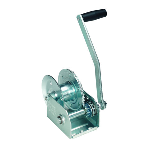
Columbia L series User manual

Pneumatic L/N/R Series
Owner’s Manual
Installation and Operating Instructions
CAUTION
The final determination as to the suitability of this product for any purpose is solely that of the user.
Columbia products are not to be used to lift people or to lift anything over people.
D00097E
Model:
Serial Number:
CFM
PSI

READ THIS FIRST.
The information in this manual is intended to help ensure your Columbia product is properly installed, operated and
maintained.
Although every effort has been made to make this manual complete and understandable, it is not a definitive guide to
every possible situation or circumstance.
The proper installation, operation and maintenance of this product is solely the responsibility of the owner.
Safe operation of this product is directly dependent on the operator’s skill, knowledge and judgment before, during and
after the use of the product.
To avoid hazardous situations, every operator must be knowledgeable about appropriate safety guidelines, codes and
regulations related to rigging, wire rope, and winch / hoist usage. Remember that an uninformed or careless operator
can make the operation of any equipment dangerous.
Ultimately, the owner / operator must make the final decision as to how this product will be used and whether that
intended use is safe.
If, after reading this manual, you have any questions regarding the installation or use of this Columbia product, contact
your dealer or the Customer Service Manager of Allied Power Products, Inc. for an answer to your question.
Replacement manuals are available free of charge by writing:
Allied Power Products, Inc.
6590 SW Fallbrook Place
Beaverton, OR 97008
THIS MANUAL CONTAINS EXTREMELY IMPORTANT INFORMATION ABOUT THE INSTALLATION
AND OPERATION OF YOUR COLUMBIA PRODUCT. FOR YOUR OWN SAFETY, READ THIS MANUAL
COMPLETELY PRIOR TO PRODUCT INSTALLATION AND / OR OPERATION.
WARNING
COLUMBIA PRODUCTS ARE NOT TO BE USED FOR
LIFTING PEOPLE OR THINGS OVER PEOPLE.

Contents
General Information...............................................................................................................................................4
Installation Guidelines...........................................................................................................................................5-7
Location............................................................................................................................................................5
Fleet Angle........................................................................................................................................................5
Mounting..........................................................................................................................................................5-6
Pneumatic Guidelines.......................................................................................................................................7
Wire Rope.........................................................................................................................................................7
Operation Instructions...........................................................................................................................................8
General Maintenance.............................................................................................................................................9-11
Troubleshooting Guide..........................................................................................................................................12
Appendix: Parts Breakdown and/or Mounting Template (if applicable)
Limited Warranty
Sample Model Number
AB CDE
WD2000-P-01
Model Number Information
When instructions in this manual refer to specific
specifications on different models, identify your
unit by referring to the model number as shown
on the unit nameplate and the front of this manual.
AH = Hoist, rated for hoisting W = Winch, rated for pulling
BModel Series
CModel Specification
DP = Pneumatic Power Source
EDrum Configuration

4
General Information
Columbia HL/WN/WR Series winches and hoist assemblies consist of a gearbox, pneumatic motor and drum assembly.
Drum
The drum is attached to the motor through planetary gear reductions to deliver the required pulling capacity and
performance. The drum consists of three basic assemblies:
1. Drum with integral ring gear
2. Output planetary gear set
3. Primary planetary gear set
Ratings and Suitability
Columbia winches and hoists are not to be used to lift, pull, support or otherwise transport people or loads over people.
Line pull ratings represent the maximum load that can be placed on a new unit. This load rating varies with the amount
of wire rope wound on the drum and is affected by the age and condition of the unit.
WARNING
DO NOT ATTEMPT TO MOVE LOADS GREATER THAN THE RATED CAPACITY.
Even if the unit appears to be able to handle the load, it can cause the unit to fail or create
undetectable damage that could cause the unit to fail while using the unit within its rated capacity.
Factors of Operation
Harsh environments decrease the load rating of the unit and make it more susceptible to damage. Avoid installation in
extreme temperatures, dirty surroundings and wet environments.
Improper installation can create excessive wear or failure of any of the component parts or fasteners in the unit. Be
sure that the unit is properly installed, the fasteners checked for tightness and the mounting inspected for damage on
a periodic basis.
Use of the unit will create wear in the components. The more frequently it is used and the heavier the load, the greater
the strain and wear on the components. This may result in damage that causes a failure over a period of time. Periodic
inspection of the unit is the only way to ensure its continued operating capability.
CAUTION
The amount of wire rope on the drum affects the performance of the unit. Line-pull decreases
with each additional layer of wire rope wound on the drum. Line-speed increases with each
additional layer of wire rope wound on the drum.

5
Installation Guidelines
The safe installation of this product is solely dependent upon the owner and/or operator’s skill, knowledge and judgment.
Installation must be done only by those qualified and familiar with all operating guidelines, safety codes and regulations
related to rigging, wire rope and winch and/or hoist usage. The determination of suitability for this product for any
specific use is the responsibility of the owner and/or operator.
The following guidelines are to be used only as a reference.
Location
When selecting a location for the unit, the following guidelines must be met:
1. An unobstructed area that keeps the operator and others out of the path of the unit and the path of broken wire rope.
Broken wire rope can snap back and cause serious injury to personnel and machinery.
2. A location where it will not interfere with or be damaged by other objects or machinery.
3. A location with adequate lighting and heat for both the operator and unit. Although the unit is rated for operation in
temperatures ranging from -50oto +125oFahrenheit, extremes in temperature will affect the performance of the unit.
4. A location that permits proper fleet angle. Maintaining proper fleet angle allows the wire rope to spool uniformly
onto the drum and prevents damage to the wire rope.
Fleet Angle
Proper fleet angle is less than 1-½omeasured as illustrated below (Diagram 1). As a “rule of thumb”, the absolute
minimum distance from the drum to a fixed sheave should be equal in feet to the drum length in inches. For example,
with a drum width of 10 inches, the minimum distance to a fixed sheave should be 10 feet.
Fleet Angle
Diagram 1
Distance
Drum
Length
Mounting
The unit must be attached to a rigid and level foundation or support structure that is adequate to support the unit and its
load under all load conditions, including shock-loads, without flexing. Three different mounting positions are shown
on the following page.
WARNING
Do not attach the unit to wood, sheet rock, or similar type materials.

6
Compression-Type Mount
If possible, a compression-type mount (unit on top of the mounting plate) should be used. This is the strongest and
safest type of mount. There must be adequate clearance for the wire rope to pass without touching the mounting plate.
Tension-Type Mount
Use a tension type mount (unit below the mounting plate) when a compression mount is not possible. This is the
second best mounting method.
Shear-Type Mount
A shear type mount (unit in front of the plate) is the least desirable. While the strength of this mount exceeds the unit’s
rated capacity, it has far less tolerance to shock-loads that exceed the rated capacity.
Di
agram 2
Diagram 2
Compression-Type MountTension-Type Moun
tS
hear-Type Moun
t
CAUTION
When using a shear-type mount, an underwound configuration (wire spooling from the
underside of the drum) is the preferred method. An overwound configuration (wire
spooling from the top side of the drum) can still be used when necessary.
Mounting Holes
The mounting hole pattern is of critical importance to the strength of the unit. Mounting holes
must
match the template
and/or drawings supplied with this owner’s manual. Any deviation from the mounting dimensions or instructions can
cause the drum supports to break under load. This can create an unsafe working condition, causing serious injury or
property damage.
The unit base
must
be flat in all directions within + 0.020 inches. An uneven base can cause binding, twisting, excessive
wear or catastrophic failure of the gear train and ultimately the unit. If necessary, use shim stock to ensure even mounting.
WARNING
Do not weld any fastener used for attaching the unit or mounting plate. Welding
makes the fasteners brittle and subject to failure even in a no-load situation.

7
Pneumatic Guidelines
This Columbia unit is driven by pneumatic power. Max pressure and flow guidelines are printed on the cover of this manual.
Air Supply and Circuit
The air supply must be clean and relatively dry. An airline filter and lubricator should be fitted in the air supply line and
located before the first control valve of the system.
If the rated performance of the motor and unit is to be obtained, all valves and pipe work of the air supply must be of adequate
size. Valves should be located as close as possible to the motor.
For short length pipe runs up to 6 feet, the supply lines should be the same size as the inlet and exhaust ports, and larger
for longer runs.
Before final connection to the motor, blow out the airlines to remove any loose scale, swarf or abrasive dust that may be
present, and squirt a few drops of oil in to the inlet ports.
CAUTION
Make sure hose pressure is at 0 PSI when making
connection to existing power sources.
Supplied compressed air is to be filtered to a minimum of 64 micron and lubricated with a suitable pneumatic or hydraulic
oil. Oil viscosity of ISO VG32 is recommended for ambient temperatures between 0o– 32oCelsius (32o– 90oFahrenheit).
If the unit is plumbed to a system without an air drying system, it is strongly recommended that an additional water separator
be added to the pneumatic circuit.
Typical oil supply rate is 8-12 drops/min, this amount may be adjusted outside of these limits as required.
The filter bowl should be drained regularly and the element examined for signs of clogging.
Safety Precautions
1. Regularly check the water separator, regulator and air supply lubricator prior to running and during operation.
2. All hose assemblies should be checked regularly for leaks, abrasion, kinks, cover blisters or any other damage.
Any assembly showing signs of wear or damage must be replaced before further use.
Wire Rope
The wire rope anchor, which attaches the first wrap of the wire rope to the drum, is not designed to hold rated loads. Keep a
minimum of five wraps of wire rope on the drum at all times to achieve rated load.
WARNING
Wire rope must be spooled on under tension before
initial use of this unit. Factory installed wire rope is not
spooled on under load.
To correctly spool the wire rope, it is necessary to unwind the wire rope and then rewind the wire rope under load. It is
recommended that during the initial tensioning of the wire rope a load of approximately 15% of the rated first layer line pull be
used. In the event that tension is taken off the line, the wire rope must be re-tensioned according to the above guidelines.

8
Anchoring Wire Rope: L Series
Take the free end of the wire rope and insert it through the small
opening of the anchor pocket. Loop the wire rope and push the
free end about half of the way back through the pocket. Install the
wedge, then pull the slack out of the wire rope. The wedge will slip
into the pocket and secure the wire rope into the drum. The early
style anchor wedge is designed to accommodate several different
sizes of wire rope. You may anchor 7/16 and 1/2 in. (11 & 13 mm)
wire rope by inserting the wedge, large end first. Anchor 9/16 and
5/8 in. (14 & 16 mm) wire rope by inserting the wedge, small end
first. Contact APPI for other wire rope sizes.
Di
agram 3
Diagram 3
7/16 - 1/2 in.
(11-13 mm) wire rope
Insert large end first.
9/
16 - 5/8 in.
(1
4-16 mm) wire rope
In
sert small end first.
Ea
rly Style
Wi
re Rope
An
chor
Anchoring Braided Rope: L Series
A special wedge is used to anchor 1 and 1 1/8 in. (25 & 28 mm)
braided synthetic rope. The installation procedure is the same as
for anchoring wire rope.
Di
agram 4
Diagram 4
1 - 1 ⅛in. braided rope
(25-28 mm)
Correct Installation
Diagram 5
Diagram 5
Drive from this side
Wedge and wire
rope fully seated
in pocket

9
Incorrect Installation
Diagram 6
Diagram 6
Wedge not
fully seated
Wedge pulled
too far th
rough
anchor pocket
Anchoring Wire Rope: N Series
Prepare the end of the wire rope as recommended by the wire rope manufacturer. Insert the free end of the wire rope
through the opening in the drum flange. Push the wire rope into the anchor pocket until the end of the wire rope is even
with the outer edge of the pocket. Install the set screws and tighten until the wire rope deforms under the set screws
and the wire rope is held securely.
The set screw anchor system is designed for use only with 9/16 - 5/8 in. (14-16 mm) wire rope.
Diagram 7
Diagram 7
Anchoring Wire Rope: R Series
Re-usable, field-installed spiral ferrules for the recommended wire rope size are supplied with all winches, and also are
available from APPI. The ferrules are for use with standard sixstrand, IWRC (Independent Wire Rope Core) type wire rope.
Step One
Insert cable through the small opening of the ferrule. Spread strands and lay them in individual grooves in spiral
wedges.
Step Two
Tap wedges and cable into the ferrule leaving approximately 3/8 in. (10 mm) extending from the top. The first load will
seat cable and wedges securely in the ferrule.
Diagram 8
Diagram 8
Step OneStep Two

10
Operating Instructions
The safe operation of this product is solely dependent upon the owner and/or operator’s skill, knowledge and judgment.
Only those qualified and familiar with all operating guidelines, safety codes and regulations related to rigging, wire rope
and winch and/or hoist usage should operate this unit.
The determination of suitability for this product for any specific use is the responsibility of the owner and/or operator.
The following guidelines are to be used only as a reference.
Preparing for Operation
Inspect the condition of all components, including mounting bolts, pneumatic connections, sheaves, wire rope, hook,
rigging, etc.
Verify the line pull required to move your desired load and make sure you do not exceed the load rating of the unit.
Test for proper forward and reverse operation without a load.
Operating the Unit
Ensure that the load is free of objects around it. Connect the load to hook with a sling or other approved device. Never
hook the wire rope around a load and onto itself.
Use the control switch on the pendant intermittently to take up wire rope slack to avoid shock-loads, which can
momentarily exceed the unit and wire rope rating. Move the load slowly at first to make sure the load is securely
attached to the hook.
Do not allow the hook to be any closer than two feet from the drum to prevent damage to the unit and wire rope.
Always inspect and carefully rewind the wire rope after each use. Improperly spooled, kinked or tangled wire rope will
damage and shorten the life of the wire rope.
Duty Cycle
All Columbia pneumatic winches and hoists are rated for continuous duty.
Braking System
Any time the unit is stopped, the brake will automatically engage against the load. Never leave any load unattended
without properly securing it.
Operating Safety Precautions
1. Never touch the wire rope or rigging while another person is at the control switch or at anytime while operating the unit.
2. Never attempt to pull a load with less than five wraps of wire rope around the drum. Fewer wraps could cause the
wire rope anchor to break and release the wire rope and load.
3. Keep the operator, assistants and spectators at a safe distance from the wire rope and rigging and out of the path of
the load during the lifting operation. If the wire rope breaks or pulls loose under load, it can lash back with enough
force to cause property damage, injury or even death.
4. Keep hands away from wire rope and hook while operating the unit. Never let the wire rope slide through your
hands. Always wear heavy leather gloves when handling wire rope.
5. Never touch the wire rope or hook while they are under load.
6.

11
General Maintenance
Maintenance of this product is the sole responsibility of the owner and/or operator.
The determination of suitability for this product for any specific use is the responsibility of the owner and/or
operator. The following guidelines are to be used only as a reference.
Periodically inspect the unit for general wear and tear. Immediately determine the cause of any change in performance
or sound during operation and take corrective action as required.
Keep unit, wire rope and remote control free from contaminants. Use a clean rag or towel to remove any dirt and debris.
If necessary, unwind the unit completely, wipe clean, and rewind properly before storage.
Gearmotor Maintenance
WARNING
Always ensure equipment is secure and air is disconnected before removing or
performing maintenance on the drive assembly.
All gearmotors are supplied with the correct grade and quantity of lubricating oil for the specified mounting position.
The oil level should be checked periodically. Remove the plated (non-painted) oil level plug. The oil level is correct when
the surface of the oil is level with the lowest point of that tapped hole.
Oil levels and oil quality should be checked at frequent intervals, depending on usage and the operating environment. Oil
changes are required at intervals of 10,000 operating hours or every two years, whichever comes first. If a synthetic oil
lubricant is used, then this period can be extended to 20,000 operating hours or every four years, whichever comes first. In
applications where hostile operating conditions exist, such as high humidity, corrosive environment, or large temperature
changes, the lubricant should be changed at more frequent intervals.
Grease packed bearings should be cleaned and regreased every 10,000 hours or 20,000 hours for synthetic grease. Input
(high speed) bearings should not be overgreased. They should be filled with grease not to exceed 1/3 of the bearing’s free
volume. For output bearings and bearings with replaceable grease shields, fill to 2/3 of their free volume.
When the recommended lubricant is not available, it is permissible to use a lubricant having equivalent characteristics but
we do not recommend that lubricants of different brands be mixed. Under no circumstances should synthetic lubricants be
mixed with one another or with one another or with one having a mineral base.
Drum
Mobilgear SHC 629 or 630 synthetic gear oil or equivalent can be utilized in temperatures from -30oF to 130oF.
CAUTION
The drum portion of the assembly is shipped with a minimum amount of lubricating
oil. Lubricating oil must be added to the drum prior to operation.

12
Gear oil changes are recommended for every 1000 hours or six (6) months of use. Use recommended type of gear
oil for prevailing ambient temperature. Annual disassembly and inspection of all wear items in compliance with
American National Standards Institute (ANSI) specification B30.5c 1987 and American Petroleum Institute (API)
recommended practice RP 2D section 3 is recommended.
The gear oil level should be checked every 500 operating hours or three (3) months, whichever occurs first. The oil
should be level with the bottom of this opening.
The gear oil should be changed after the first one hundred (100) hours of operation, then every 1,000 operating
hours or six (6) months, whichever occurs first. The gear oil must be changed to remove wear particles that
erode bearings, gears and seals. The gear oil should also be changed whenever the ambient temperature changes
significantly and an oil from a different temperature range would be more appropriate.
Approximate Oil Capacities
HL Series, -01 Drum 6 pints
HL Series, -02 Drum 6 pints
HL Series, -04 Drum 7 pints
HL Series, -05 Drum 7 pints
WN Series, -01 Drum 5 pints
WR Series, -01 Drum 15 pints
WR Series, -04 Drum 14 pints
WARNING CAUTION
Always ensure equipment is secure
and air is disconnected before
removing or performing maintenance
on the drive assembly.
When the recommended lubricant is not available, it is
permissible to use a lubricant having equivalent characteristics
but we do not recommend that lubricants of different brands be
mixed. Under no circumstances should synthetic lubricants
be mixed with one another or with one having a mineral base.
HL Series
Diagram 3
Diagram 3
Vent
Oil Level Sight Gauge
SAE -16 ORB Port
Oil Fill*
*SAE-8 ORB Port
Rotate drum as needed to fill/drain
Drain Port*

13
HN/WN Series
Diagram 4Diagram 4
Vent/Fill Po
rt
Level Port
Freespool Port
1/4-18 NPTF
Drain Port
1/2-14 NPTF
TYP #3
Not used
HR/WR Series
Diagram 5Diagram 5
Vent
Oil Level
Sight Gauge
SAE -8 ORB Port
Freespool Port
SAE -6 ORB Po
rt
Drain Port
SAE -8 ORB Po
rt
Oil Fill
SAE -8 ORB Port
Wire Rope
Inspect the wire rope before and after each operation. The life of the wire rope is directly related to the care and use it
receives. Wire rope must be replaced when it has one or more of the following defects as defined in the American National
Standards Industry Handbook A10.5 or as defined by OSHA:
• Corrosion
• Frayed or broken wire
• Abrasions
• Kinking
• Heat damage
• Any apparent reduction of wire rope diameter
STOP USING THE UNIT AND REPLACE THE WIRE ROPE
if any of the defects listed above are discovered.
Using light oil on the wire rope and hook can keep rust and corrosion from forming.

14
Troubleshooting Guide
General Symptom Potential Cause
Unit will not produce line
pull/line speed as listed.
1. Inadequate air pressure/flow.
2. Air motor is not properly lubricated.
3. Air is restricted (line, mufflers, etc.)
4. Unit is mounted to an uneven surface.
5. Cable sheaves or block purchase not turning freely.
6. Load is constrained.
Unit will lower load, but
will not raise load.
1. Load is beyond rated capacity.
2. Load is constrained.
Wire rope stacks against
flanges.
1. Unit is not level.
2. Line leads to a point not in line with the drum.
3. Distance to cable sheaves, block purchase or load inadequate for proper fleet angle
Wire rope spools poorly.
1. Wire rope tension was lost.
2. Wire rope not installed properly.
3. Tension not adequate to spool wire rope on tightly.
4. Distance to cable sheaves, block purchase or load inadequate for proper fleet angle.

NOTES
15

NOTES
16

NOTES
17

LIMITED WARRANTY
Allied Power Products, Inc. (APPI) warrants the products it manufactures to be free from defects in material
and workmanship to the original buyer for a period of 24 MONTHS from the date of shipment from APPI. All
warranties for products sold but not manufactured by APPI are solely that of the manufacturer.
This warranty and liability of APPI is limited to the replacement or repair of any product manufactured by APPI if
the product is found – upon examination at our facility – defective due to materials or workmanship. All freight,
removal and/or installation charges shall be borne by the Buyer.
This warranty does not cover failures or malfunctions found by APPI to result from:
•Improper installation, operation and/or maintenance of the product.
•Replacements, repairs and/or alterations made by or on behalf of the buyer without written approval from
APPI.
•Use of accessories and/or other components in conjunction with the product without written approval from
APPI.
APPI SHALL NOT IN ANY EVENT BE HELD LIABLE FOR ANY CONSEQUENTIAL OR INCIDENTAL DAMAGE OR
FOR EXPENSES OR DELAY CAUSED BY DEFECTIVE MATERIAL OR WORKMANSHIP.
Except for the above warranty, APPI makes no other express or implied warranties and NO WARRANTY OF
MERCHANTABILITY OR FITNESS FOR A PARTICULAR PURPOSE.
This warranty shall be governed by and construed in accordance with the laws of the State of Oregon and
enforced in Oregon courts. If any portion of this limited warranty and limitation on damages is determined to be
invalid or unenforceable, the remainder of the warranty shall remain in full force and effect.
All warranty claims must be submitted to APPI in writing to:
Allied Power Products, Inc.
6590 SW Fallbrook Place
Beaverton, OR 97008
WARNING
COLUMBIA PRODUCTS ARE NOT TO BE USED
FOR LIFTING PEOPLE OR THINGS OVER PEOPLE.
Other manuals for L series
1
This manual suits for next models
2
Table of contents
Popular Winch manuals by other brands

Comeup
Comeup CP-200 instruction manual

Warrior Winches
Warrior Winches S2500EN owner's manual

Badland
Badland ZXR 3500 user manual

Ramsey Electronics
Ramsey Electronics WILDCAT 130K Operating, Service and Maintenance Manual

Mile Marker
Mile Marker SEC18 Installation & operator's manual

SVERO
SVERO 16 User instructions