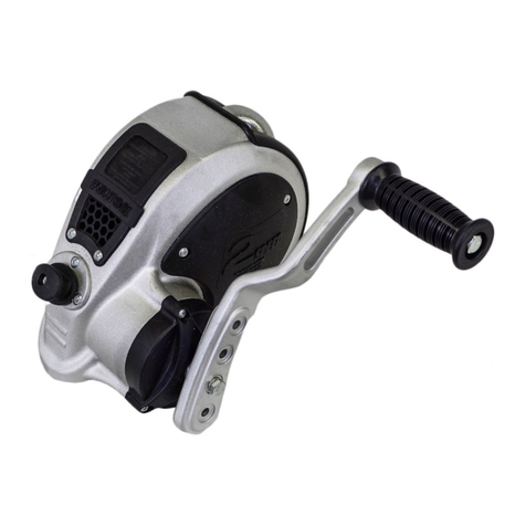
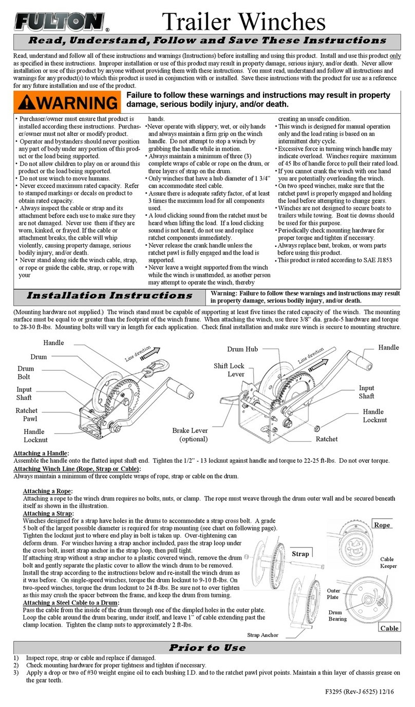
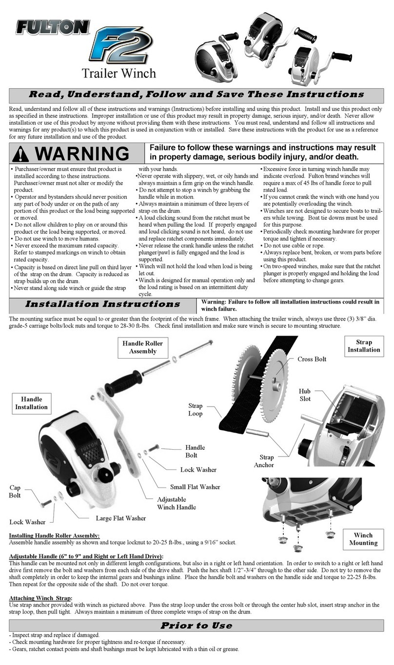
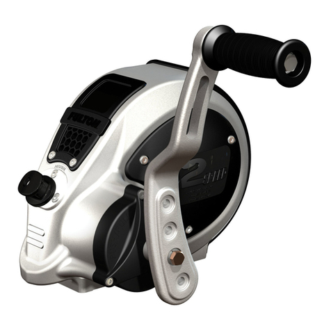
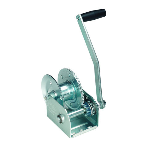
FULTON XLT 7.0 User manual

XLT 7.0, XLT 10.0
Marine Winch - French
Manuel d’instructions
XLT 7.0, XLT 10.0
Marine Winch - Spanish
Manual de instrucciones
XLT 7.0, XLT 10.0
Marine Winch
Instruction Manual
XLT 7.0 PN: 500620
XLT 10.0 PN: 500621 Visit
Fultonperformance.com
Ceqpat.com
SCAN NOW TO LEARN MORE
Use your smart device to scan
the QR code and get the latest:
•Instruction's manual
•How-to videos
•News on our products

Read, Understand, Follow and Save These Instructions
Table Of Contents
indicates a hazardous situation
which, if not avoided, could
result in death or serious injury.
Is used to address situation
that, if not avoided, could
result in propertydamage.
Indicates a hazardous
situation which, if not avoided
could result in minoror
moderate injury.
TOOLS REQUIRED
Adjustable Wrench 3/8” Ratchet 9/16” Socket 9/16” Combination Wrench
•Read, understand, and follow all these instructions and warnings before installing and using this
product.
•Install and use this product only as specified in these instructions.
•Improper installation or use of this product may result in property damage, serious injury, and/or
death.
•Never allow installation or use of this product by anyone without providing them with these
instructions.
•You must read, understand, and follow all instructions and warnings for any product(s) to which
this product is used in conjunction with or installed.
•Save these instructions with the product for use as a refence or any future installation and use of
the product.
•Scan QR code for the latest instructions.
Throughout this manual, WARNING, CAUTION, NOTICE, and the SAFETY ALERT symbol will be used
The safety alert symbol alerts you to potential physical injury hazards.
Obey all safety messages that follow this symbol to avoid possible injury or death.
©2021 Horizon Global Americas Inc. • F4088-00 REVD (7871) 08/2021
WARNING CAUTION NOTICE
E2
Safety
Page
Tools required …………………………………………………………………………………………………………………………………………….
E2
Important safety messages …………………………………………………………………………………………………………………………
E3
Know your winch ………………………………………………………………………………………………………………………………………..
E4
Features and ratings ……………………………………………………………………………………………………………………………………
E5
Instructions
Installation instructions ………………………………………………………………………………………………………………………………
E5
Remote control use …………………………………………………………………………………………………………………………………….
E10
Best practices ……………………………………………………………………………………………………………………………………………..
E11
Operation instructions ………………………………………………………………………………………………………………………………..
E12
Maintenance
……………………………………………………………………………………………………………………………………………… E13
Checklist ……………………………………………………………………………………………………………………………………………………..
E14
How to order ………………………………………………………………………………………………………………………………………………
E14
Legal ……………………………………………………………………………………………………………………………………………………………
E15
Limited warranty …………………………………………………………………………………………………………………………………………
E15

Important Safety Messages
Before first operation .
•NEVER exceed maximum
rated capacity. Refer to
table 5 to obtain rated
capacity. If uncertain,
contact Horizon Global at
1-800-632-3209 or go to
fultonperformance.com
•Understand your winch
and its instructions.
•Purchaser/owner must
ensure that product is
installed according to these
instructions.
•Purchaser/owner must not
alter or modify product.
•This winch is rated for the
first layer of strap on the
drum for intermittent use
duty cycle.
Setup .
•ALWAYS remove
jewelry and wear ear and eye
protection.
•ALWAYS use leather
gloves when handling the
strap & hook.
•ALWAYS
stand clear of winch strap,
hook, fairlead, and load.
•ALWAYS keep others away
while winching.
•
ALWAYS ensure the operator
and bystanders are aware of
the stability of the vehicle
and load.
•ALWAYS be aware of
possible hot surfaces at
winch motor or drum during
or after winch use.
•NEVER operate this winch
when under the influence of
drugs, alcohol, or medication.
•NEVER allow children to play
on or around this product, or
the load being supported.
•NEVER let winch strap slip
through your hands.
•NEVER touch a winch strap or
hook when someone else is at the
controls.
•NEVER touch winch strap or
hook while under tension or
under load.
•NEVER use the winch
as a lifting device or a hoist for
vertical lift.
•NEVER use the winch to
lift, support or otherwise
transport humans.
•Operator and bystanders
should NEVER position any part
of body under any portion of this
product, or the load being
supported.
Is your winch ready to pull? .
•ALWAYS inspect the winch strap
and hook for damage or wear
before operating winch. Frayed,
kinked or damaged winch strap
must be replaced immediately.
Damaged components must be
replaced before operation.
•ALWAYS be certain that the
winch stand can withstand the
load.
•ALWAYS use a hook with a latch.
•ALWAYS ensure hook
latch is closed & supporting load.
•ALWAYS remove any element
or obstacle that may interfere
with safe winch operation.
•NEVER use winch rope or
strap for towing.
•NEVER use excessive effort to
free-spool winch strap.
•NEVER wrap winch strap back
onto itself.
•NEVER apply load to
hook tip or latch. Apply load
only to the center of hook.
•NEVER use a hook whose
throat opening has increased,
or whose tip is bent or twisted.
•NEVER operate the winch in a
stop-and-go fashion. Specially
when under load.
•Periodically check
mounting hardware for
proper torque and tighten
if necessary.
•Strap can break without
warning. ALWAYS keep a
safe distance from the
winch and strap while the
winch is under a load.
During the pull .
•ALWAYS ensure that the
clutch is fully engaged.
•ALWAYS avoid side pulls,
which can pile up winch rope
or strap at one end of the
drum. This can damage the
winch strap or winch.
•ALWAYS secure the boat
with a separate safety chain
or tie down, not the winch.
•NEVER exceed winch or
winch strap rated capacity.
•NEVER use the winch to
secure the load.
•NEVER use the winch to
secure a boat to a trailer.
•NEVER shock load the
winch.
•NEVER engage or
disengage the clutch
when the winch is under
load, or the drum is
moving.
•NEVER submerge winch in
water.
•Pull from an angle of less
than 5°laterally to avoid the
strap from piling onto one
side of the drum.
•Not following these
instructions may lead to
premature wear or damage
to the winch.
After use .
•Wash externally with
mild soap and water.
•Dry completely before
storing.
©2021 Horizon Global Americas Inc. • F4088-00 REVD (7871) 08/2021 E3

Figure1 - WinchComponents
Know Your Winch
Front
LED light
Bottom
LED light
(Not shown)
Multi-position
fairlead mount
Removable
cover
Winch line
IN/OUT Lights
ON/OFF
Strap
Manual
override
Mounting
Hardware Wireless
Remote
Swivel
hook
Clutch knob
Hawse
fairlead
©2021 Horizon Global Americas Inc. • F4088-00 REVD (7871) 08/2021
E4

WARNING
Features and Ratings
Table 1 - Winch Ratings / Specifications
XLT 7.0 XLT 10.0
Max.
Recommended Boat Weight
*
7,000 lbs.
Max.
Recommended Boat Weight
*
10,000 lbs.
Wireless Remote Control Yes Wireless Remote Control Yes
Light Yes Light Yes
Power Source 12V Power Source 12V
Max. Amp Draw 160 amp Max. Amp Draw 200 amp
Strap 2” x15’ Strap 2” x15’
Brake Mechanical Brake Mechanical
Clutch (free-spooling) Turn Knob Clutch(free-spooling) Turn Knob
Controls
Remote
/ Switch
on Winch Controls
Remote
/ Switch
on Winch
Current draw (Amperage) and line speed vary according to the load, boat position, trailer position,
trailer configuration, battery charge level, the angle of the ramp, how submerged the trailer is -
related to the boat, and other factors.
Monitor operation closely for changes in sound or winch speed to avoid overloading your winch.
As the boat gets closer to the bow stand, the strap will build up to a larger diameter on the drum,
reducing the efficiency of the winch.
Installation Instructions
BEFORE INSTALLING AND USING YOUR POWERED WINCH, READ AND
FOLLOW ALL MOUNTING INSTRUCTIONS AND SAFETY MESSAGES
Mounting
Toprevent accidental activation of the winch and serious injury, complete the winch installation
and attach the hook before installing the wiring and applying power
1. Before Installation
1.1 Inspect Parts
Instruction/Owners Manual
Winch Assembly
Clutch Knob
Power Leads
Wireless Remote
Strap and Hook
Hawse Fairlead
Mounting Hardware
Approximate distance for the boat to first
contact the trailer, while it is still mostly floating
Approximate distance for the boat to come out
of the water and be pulled on the trailer by the
winch, while it is no longer mostly floating
* Refers to the 1st layer capacity in marine applications. Refer to the “Best Practices” page for more details.
©2021 Horizon Global Americas Inc. • F4088-00 REVD (7871) 08/2021 E5

WARNING
Table 2 - Mounting Torque Requirements
Powered
Winches XLT7.0 XLT10.0
Winch
MountingBolt Size
•
Three3/8”-16 Gr.5 carriagebolts
•
Three3/8” retaining washers
•
Three3/8” NY-Lock nuts
•
Three3/8”-16 Gr.5 carriagebolts
•
Three3/8” retaining washers
•
Three3/8” NY-Lock nuts
Winch
MountingBolt Torque 28-30 ft./lbs. 28-30 ft./lbs.
Installation Instructions
Mounting Hardware Requirements
Refer to Table 2 below for bolt quantity, sizes, and required torque. Mounting system will dictate bolt
length.
ALWAYStorque mounting bolts to the values specified for your winch in Table 2.
ALWAYSuse grade 5 (class 8.8metric) hardware.
NEVERweld mounting bolts.
ALWAYSchoose the proper bolt length for yourapplication.
ALWAYSconfirm required bolt length to ensure proper thread engagement. A minimum of two whole
threads shouldprotrude from the nut.
1.2 Select Mount Location
ALWAYS choose a mounting location that is sufficiently strong to withstand the maximum
pullingcapacity of your winch.
1.2.1 Winch Mounting
Considerations
Your mounting surface must be equal to or
greater than the mounting surface of the
winch frame. See Figure 3. Three sets of
3/8”, Grade 5, hardware are required to
mount this winch.
The winch should be positioned so that the
strap exits the winch horizontal to the bow
eye when the boat is fully loaded onto the
trailer.
The fairlead should be a minimum of 6” away
from the bow eye when the boat is fully loaded
onto the trailer. See Figure 2.
Figure3 - MountingSurface
Minimum
Mounting
Area
4.5” x6”
Figure2 - MountLocation
Minimumdistance
from the bow eye to
thewinch,whenthe
boat is fullyloaded
on to the trailer
6”
WARNING
©2021 Horizon Global Americas Inc. • F4088-00 REVD (7871) 08/2021
E6

Installation Instructions
1.2.3 Mounting Configurations
Wind the strap from the bottom of the drum.
See Figure 5.
1.2.2 Easy Install System
Place the three 3/8”, Gr. 5, carriage bolts
with the retaining washers in place, into the
“T” slot on the base of the winch.
Place winch over the mounting plate and
insert the bolts through the mounting holes
in the mounting surface of your winch stand.
Secure the flanged lock nuts to the
mounting bolts. Torque to 28-30 ft.-lbs. Be
sure that a minimum of two complete
threads showafter tightening the flange lock
nuts. See figure 4.
Under-windOnly
Figure5 - UnderWound
Failure to adequately align, support, or attach the winch to a suitable mounting base may result
in property damage, personal injury and/or death.
1.3 Hawse Fairlead
The use of a Hawse Fairlead can reduce the contacting friction with the strap. An aluminum hawse
fairlead is recommended because it has no sharp edges and resists wear damage more effectively
than a roller fairlead. The fairlead does not ensure the strap will wind onto the drum in an orderly
manner.
1.4 Wiring
1.4.1 Install the Wiring
BEFORE installing the winch, make sure all electrical parts are corrosion free.
NEVER lean over battery while making connections.
NEVER route electrical cables over battery terminals.
Run the charging system (if installed) during winching operations to keep battery charged.
NEVER route electrical cables across sharp edges.
NEVER route electrical cables near parts that get hot.
NEVER route electrical cables through or near moving parts.
ALWAYS avoid pinch and wear/abrasion points when installing all
electrical cables.
ALWAYS insulate and protect all exposed wiring and electrical terminals.
Figure4 - Mounting
Retaining
Washers
Failure to install the strap in the correct
under-wind condition may result in property
damage, personal injury, or death.
WARNING
WARNING
WARNING
©2021 Horizon Global Americas Inc. • F4088-00 REVD (7871) 08/2021 E7

Installation Instructions
1.4.2 Battery Recommendations & Lead Size
A fully charged battery and good connections are essential for the proper operation of your winch.
The minimum requirement for the battery is 650 cold cranking amps. The distance from the battery
to the winch will have an effect on the voltage applied to the winch. The further the distance, the
more voltage drop will occur. To help reduce voltage drop, larger wire gauges will be required for
larger distances. Refer to table 3 for minimum wire gauge recommended, based on the distance
from the battery to the winch.
Table 3 - Wire Size by Length
WIRE LENGTH
5’ 10’ 15’ 20’ 25’
WIRE SIZE 7 gauge
(10 mm2)6 gauge
(13 mm2)4 gauge
(21 mm2)4 gauge
(21 mm2)2 gauge
(34 mm2)
1.4.3 Battery Cable Routing
ALWAYS route battery cables along a path that allows the cables to be secured with zip ties.
Loose or unsecured power cables can cause serious injury or death.
Option 1: This option will require the battery to be charged when not in use.
1. Secure your battery to the trailer.
2. Connect the positive and negative leads directly to the battery.
Option 2:
1. This option is ideal when a boat always uses the same tow vehicle.
2. Using table 3, select the correct wire gauge for the length of wire used.
3. Plan the routing path.
4. Loosely secure the power wire along the path.
5. Confirm that the power wire is protected from sharp edges, heat, and moving parts. Consider
chassis flex, and vibration, which might damage the wire.
Figure6 - WiringOption 1
WINCH
BATTERY
Figure7 - WiringOption 2
QUICK CONNECT PLUG
BATTERY
WINCH
GROUND
It ishighly recommended thatthe connection of the wiringfor option2 be performed by an expert installer
WARNING
NOTICE
©2021 Horizon Global Americas Inc. • F4088-00 REVD (7871) 08/2021
E8

Installation Instructions
1.5.2 Wireless Remote Operation
Your wireless remote control device comes
pre-programmed and ready to use. Your wireless
remote has an auto shutdown feature.
The remote control has four buttons:
1. Press and hold the bottom button to turn the
wireless remote control and an indicator light ON or
OFF.
2. The second button on the remote turns the winch
lights ON or OFF.
3. The top two buttons power the winch line IN and
OUT.
Option 2 (continued):
6. Carefully inspect electrical wire routing. Zip-tie and secure electrical wires. Zip-ties should be
snug, but not cutting into the wire insulation. Use electrical tape, pieces of rubber hose, or
electrical conduit to protect electrical wires and wire harness where needed to avoid electrical
wire insulation wear or abrasion.
7. Once your power lead is routed and securely fastened, attach the rear end of the power wire into
the quick connect plug.
8. Use a short ground lead (the same gauge as the power lead) and connect it to the quick connect
next to the power lead.
9. Take the quick connect and mount it to the back of the tow vehicle.
10. Takethe short ground lead and secure it to the vehicle's frame.
11. Connect your second quick connect to the winch leads.
12. Connect the power leads to the tow vehicle’s battery.
1.4.4 System Check
Upon completion of installation, check winch for proper operation. The voltage drop for the winch
motor must not exceed 10% of the nominal voltage of 12V DC.
1.5 Know Your Wireless Remote
Never lose sight of the winch while using the wireless remote.
Never touch the winch or jack while the remote is in someone else’s hands.
1.5.1 Wireless Remote and Transmitter Specifications
1. Transmission range: 50 to 90 ft (15 to 27 m)
2. Operating temperature range: -20°C to +70°C
3. 2.4 GHz wireless transmission technology.
4. The remote control uses one 12V MN21/23 battery.
Figure8 - WirelessRemote
WARNING
©2021 Horizon Global Americas Inc. • F4088-00 REVD (7871) 08/2021 E9

Operation Instructions
2.1 Spooling in, Under Load
NEVER exceed winch’s rated line pull. Power-in the winch strap evenly and tightly on the drum.
NEVER touch winch strap or hook while someone else is at the control switch or during winch-
ing operation.
NEVER overload the motor to stall. If the motor stalls, allow it to cool for 15 minutes, to reduce
the chance of motor burnout.
Do not shock load the winch when spooling. Avoid shock loads when spooling by pulsing the control
switch to take up winch strap slack. Shock loads can momentarilyfar exceed the winch and strap ratings.
2.2 Overloading / Overheating
This winch is rated for intermittent duty. When the motor approaches stall speed, very rapid heat
buildup occurs which may cause motor damage.
1.5.3 Indicator Light
1. When the remote is turned on it will search for a signal for 1 to 3 seconds. If a signal is found the
blue light will stay on.
2. If the winch is not powered up or you are out of range, the blue light will blink regularly.
1.5.4 Pairing Wireless Remote
1. Ensure that both winch cables are disconnected from the battery, and the remote is turned off.
2. Connect the red terminal from the winch, to the battery.
3. Press and hold the remote’s ON/OFF button until the flashing blue LED light appears.
4. Simultaneously press and hold the LINE IN and the LINE OUT buttons for 5 seconds. Do not
release the buttons yet.
5. While holding the LINE IN & LINE OUT buttons, Connect the black terminal to the battery.
6. Release the LINE IN and LINE OUT buttons.
7. Wait for the remote’s blue LED light to remain steady.
8. Test the remote. If the light remains blinking and/or the remote does not operate, follow the
troubleshooting guide in table 4.
Remote Control Use
Table 4 –Remote Pairing Troubleshooting
FlashMode Reason Solution
1
Blinking
blue light
The remote is
searching for a
signal from the
winch
If the
LED light doesn’t stop blinking after releasing the LINE IN &
LINE
OUT
buttons:
a. The remote was not able to pair.
• Disconnect the black terminal from the battery,
repeat pairing steps 3-7.
2
Steady
blue light
The remote has
successfully
paired to the
winch
If the blue light remains steady, but the remote doesn’t appear to work:
a. Turn the remote off.
b. Wait 30 seconds and turn the remote back on.
c. Test the remote.
• If it still doesn’t work, disconnect the black terminal
from the battery, turn off the remote, and
repeat steps 2-7.
3
Light not
turning ON
Dead battery
If the blue
LED light does not appear after holding the ON/OFF button
for 5 seconds:
a. Remove the remote’s cover.
b. Inspect and replace the battery if necessary.
DO NOT power the hook into the fairlead.
This could cause damage to the fairlead.
WARNING
NOTICE
Horizon Global’s Customer Service 1-800-632-3290
©2021 Horizon Global Americas Inc. • F4088-00 REVD (7871) 08/2021
E10

Best Practices
Table 6 - GUIDE TO ROLLING LOAD CAPACITY*
Maximum allowable weight for a rolling load
RAMP INCLINATION
MODEL 0°3°5°10°15°20°
XLT 7.0
25,000 lbs.
11,340 Kg
20,000 lbs.
9,070 kg
15,000 lbs.
6,800 kg
10,000 lbs.
4,535 kg 8,500 lbs.
3,855 Kg 7,000 lbs.
3,175 Kg
XLT 10.0
35,000 lbs.
15,875 kg
30,000 lbs.
13,600 kg
25,000 lbs.
11,340 kg
20,000 lbs.
9,070 kg
15,000 lbs.
6,800 Kg
10,000 lbs.
4,535 Kg
Table 5 - Rated 1st Layer Capacity (Max.)
MODEL Pull1Roll Marine2
XLT 7.0 2,500 lbs. See table 6 7,000 lbs.
XLT 10.0 3,500 lbs. See table 6 10,000 lbs.
1Not to be used as hoist.
2When trailer is equipped with rollers, and on a maximum
incline of 20 degrees. Wooden and/or carpeted bunks will
significantly reduce this capacity.
15°
10°
5°
3°
All capacities shown are with 2’ of strap on the reel and 10% rolling friction factor.
The winch’s capacity will be reduced by approximately 10% with each layer added to the reel.
In order to ensure long term performance of your XLT Winch, and to prevent premature wear,
ensure you follow the guidelines below:
1. Never exceed the rated capacity of the winch for your application.
2. Do not exceed the recommended operational time for the winch.
3. Make sure that all electrical connections to the battery are correct, tight, and clean.
4. Do not operate in a repeated “stop-and-go” manner.
5. Immediately stop the winch if it begins to slow down excessively and/or if it feels like it is struggling
to reel in. This is a sign that the rated capacity has been exceeded, and rapid buildup of excessive
heat will occur.
1-minute of operation, followed by a 14-minute cool-down period
WARNING
©2021 Horizon Global Americas Inc. • F4088-00 REVD (7871) 08/2021 E11

Do not use the winch as a lifting device or a
hoist for vertical lifting.
The “Power-Out” function should be used for relieving tension on the strap,
not for extended distances.
The “power out” function drives the winch motor against the brake which is similar to driving your
vehicle with the parking brake engaged. Do not use the Power-Out function for lowering a load.
Winches are not designed to be used as hoists. Use the free-spool function to pay out strap. If
you power out over 25 feet, let the winch cool for 15 minutes.
Operation Instructions
NEVER engage the clutch while the drum is
rotating.
1.Disengage Clutch For
Free-Spooling
Turn the clutch knob to the free-spool position.
Strap can now free-spool off the drum.
Figure 10.
2. Engage Clutch For Winching
Turn the clutch knob to the engaged position.
Never engage the clutch while the drum is rotat-
ing. Figure 11.
2.3 Safe Working Conditions
The operator should ALWAYSoperate the winch from a safe position when pulling a load. The
safest area is perpendicular to the winch strap.
The safe position will help prevent the strap from striking the operator if the strap fails when under load.
NEVER work around the winch strap while it is under load.
NEVER step over a winch strap while it is under load.
ALWAYS use caution when working with electricity and remember to verify that no exposed
electrical connections exist before energizing your winch circuit.
2.4 Clutch Operation
NEVER engage or disengage clutch if winch is under load, winch strap is in tension or drum is
moving.
Toprevent damage, ALWAYS fully engage or fully disengage the clutch knob.
The clutch lever, located on the winch housing opposite the motor, controls the clutch position. When
the clutch is engaged, the gear train is coupled to the winch drum and power can be transferred from
the winch motor. Figure10 - DisengageClutch
Disengaged
Figure11 - EngageClutch
To engage,
turn knob
WARNING
WARNING
WARNING
WARNING
CAUTION
CAUTION
©2021 Horizon Global Americas Inc. • F4088-00 REVD (7871) 08/2021
E12

Maintenance
Figure11 - ReplacingThe Strap
4. Removethe two bolts from the split collar.
5. Removethe split collar.
Figure14 - InstallNewStrap
Figure15 - InstallRetainingPin&SplitCollar
6.Removetheworn strapand thestrap
retainingpin.
7. Insert thestrapthrough the Hawsefairlead and insert
thestrapretainingpinthrough thestrap loop.
8. Insertthestrapretainingpinand strapinto the
groove on thewinch drum.
9. Replacethesplit ring collarand torque bolts to
24 ft.-lbs.
10. Replacetheside cover.
11. Replacetheclutchknob. Torqueto12 ft.-lbs.
12. Windstrapontodrumbypushingand holding the
“LINE IN” button untilthe strapisspooled ontothe
drum.Keeptensionon the strapwhileit is winding.
Figure13 - RemoveStrapRetainingPin
Retaining
Pin Figure16 - ReplaceCover&ClutchKnob
Be sure that the strap is under-wound.
Figure12 - RemoveSplitCollar
3.1 Strap Replacement
1. Disengagetheclutch knob.
2. Un-spool theentirestrap.
3. Removetheclutch knoband sidecoveras shown.
Removable Cover
ClutchKnob
©2021 Horizon Global Americas Inc. • F4088-00 REVD (7871) 08/2021 E13

Maintenance
Toprevent SERIOUS INJURY, DEATH and PROPERTY DAMAGE, you should read, understand
and follow the warnings and instructions in this manual.
For assistance with this product or to order replacement parts, please contact:
Horizon Global Americas Inc.,
47912 Halyard Dr. Suite 100
Plymouth, MI 48170
1-800-632-3290
http://www.fultonperformance.com/
3.2 Pairing Replacement Remote
The remote transmitter and receiver are paired and cannot be interchanged. If a wireless remote
(transmitter) is lost, a new one can pair itself to an existing receiver. The pairing method is descrided
in Page E10
If the red LED is blinking, the remote needs to be paired again.
3.3 Lubrication
All moving parts in the winch are permanently lubricated at the time of assembly. Under normal
conditions factory lubrication will suffice. If re-lubrication of gear box is necessary after repair or
disassembly, use Shell EP2 or equivalent grease. Never lubricate the brake system.
3.4 How To Order Replacement Parts
For Horizon Global Tech Service Department, dial 1-800-632-3290.
Table 5 - Checklist Before first
use
After EVERY
use Every 90
days
•
Read, understand, and follow the warnings and instructions in this
manual. X
•Check all the fasteners and verify that there are at the proper
torque.
•Replace as necessary. X X
•Check that the wiring is correct, and the connections are tight. X X
•Check that there are no damaged (chafed, cut, etc.), bare or
exposed wires, or terminals.
•Repair or replace any components as necessary. X X
•Check the condition of the strap and hook.
•If the strap or hook are damaged or work, discontinue use and
replace immediately. X X X
•Keep winch, strap, and switch controls free from contaminants.
•Use a clean rag or towel to remove any dirt and debris. X
WARNING
©2021 Horizon Global Americas Inc. • F4088-00 REVD (7871) 08/2021
E14

Mark Warning
Thisisa ClassBproduct, ina domestic environment,this product maycause radio interference, inwhich case
theusermaybe requiredto take adequate measures.
Standard compliance of EC Directives
TheECdirective includes the following individualdirectives
MachineryDirective 2006/42/EC
It applies to independently functional machinery or the interlinking machines to form entire systems.The
complete machine and plant must always fulfill the directive.
Electromagnetic CompatibilityDirective (EMC) 2004/108/EC
It applies to most electricaland electronic apparatus, that is, finished products and systemsthat include
electrical and electronic equipment to ensure that the electromagnetic disturbance generated by apparatus
does not exceed a level allowing radio and telecommunications equipment and other apparatus to operate as
intended, and that apparatus has an adequate level of intrinsicimmunityto electromagnetic disturbance to
enable it to operate asintended.
Patent Info: CEQPAT.com
Legal Warnings
Limited Warranty
Limited Warranty. Horizon Global Americas Inc. (“We” or “Us”) warrants to the original consumer purchaser only
(“You”) that the product will be free from (a) defects in both material and workmanship for the lifetime of your Fulton®
Winch and (b) the electrical components will be free from defects in both material and workmanship for a period of 5
(five) year. Ordinary wear and tear excepted; provided that installation and use of the product is in accordance with
product instructions. There are no other warranties, express or implied, including the warranty of merchantability or
fitness for a particular purpose. If the product does not comply with the applicable limited 5 year warranty, Your sole
and exclusive remedy is that We will replace the product without charge to You and within a reasonable time or, at our
option, refund the purchase price. This warranty is not transferable. This warranty excludes the strap and the finishes
on the winch.
Limitations on the Warranty. This limited warranty does not cover: (a) normal wear and tear; (b) damage through
abuse, neglect, misuse, or as a result of any accident or in any other manner; (c) damage from misapplication,
overloading, or improper installation, including welds; (d) improper maintenance and repair; and (e)product alteration in
any manner by anyone other than Us, with the sole exception of alterations made pursuant to product instructions and
in aworkmanlike manner. Tamperingwith or removingtheserial numberwill void your warranty.
Obligations of Purchaser. To make a warranty claim, contact Us at 47912 Halyard Dr. Suite 100, Plymouth, MI
48170, 1-800-632-3290, identify the product by model number, and follow the claim instructions that will be provided.
Any returned product that is replaced or refunded by Us becomes our property. You will be responsible for return
shipping costs. Please retain your purchase receipt to verify date of purchase and that You are the original consumer
purchaser. Theproduct and the purchasereceiptmustbe provided to Us in order to process Your warranty claim.
Remedy Limits. Repair or replacement is your sole remedy under this limited warranty, or any other warranty related
to the product. We shall not be liable for service or labor charges incurred in removing or replacing a product or any
incidentalor consequentialdamagesof any kind.
Assumption of Risk. You acknowledge and agree that any use of the product for any purpose other than the
specified use(s) stated in the product instructions is at Your own risk.
Horizon Global Americas Inc. reserves the right to change product design without notice. Horizon Global
AmericasInc. shall have no obligationto upgrade or otherwisemodify previouslymanufactured products.
Governing Law. This limitedwarranty givesYou specificlegal rights, and You also may have other rights
which vary from state to state. This limited warranty is governed by the laws of the State of Michigan, without regard
to rules pertaining to conflicts of law. The state courts located in Oakland County; Michigan shall have exclusive
jurisdictionfor any disputes relating to this warranty.
©2021 Horizon Global Americas Inc. • F4088-00 REVD (7871) 08/2021 E15

XLT 7.0, XLT 10.0
Treuil Nautique
Manuel d'instructions
XLT 7.0 PN: 500620
XLT 10.0 PN: 500621 Visite
Fultonperformance.com
Ceqpat.com
SCANNEZ MAINTENANT POUR EN SAVOIR PLUS
Utilisez votre appareil intelligent pour scanner le
code QR et obtenir les dernières:
•Manuel d’instructions
•Vidéos explicatives
•Nouvelles sur nos produits

Lire, comprendre, suivre et enregistrer ces instructions
Table des matières
Indique une situation
dangereuse qui, si elle n’est
pas évitée, pourrait causer la
mort, ou des blessures graves.
Indique une situation
dangereuse qui, si elle n’est pas
évitée, pourrait causer des
dommages matériels.
Indique une situation dangereuse
qui, si elle n’est pas évitée, peut
causer des blessures mineures
ou modérées.
OUTILS NÉCESSAIRES
• Lire, comprendre et suivre toutes ces instructions et avertissements avant d’installer et
d’utiliser ce produit.
•Installer et utiliser ce produit uniquement comme spécifié dans ces instructions.
•Une mauvaise installation ou utilisation de ce produit peut entraîner des dommages
matériels, des blessures graves et/ou la mort.
• Ne jamais permettre à quelqu’un d’installer ou d’utiliser ce produit sans vous donner ces
instructions.
•Vous devez lire, comprendre et suivre toutes les instructions et avertissements pour tout
accessoire avec lequel ce produit est utilisé ou installé.
•Conservez ces instructions avec le produit pour être utilisé comme référence pour toute installation et
utilisation du produit à l’avenir.
•Scannez le code QR pour les dernières instructions.
ToutaulongdeceManuel,dessymbolesd’AVERTISSEMENT, D’ attention, et d’AVIS seront utilisés
Le symbole d’alerte de sécurité vous avertit des risques potentiels de blessures physiques.
Observez tous les messages de sécurité suivant ce symbole afin d’éviter d’éventuelles
blessures ou décès.
Clé réglable Cliquet 3/8 po Douille 9/16 Clé mixte 9/16 po
AVERTISSEMENT ATTENTION AVIS
©2021 Horizon Global Americas Inc. • F4088-00 REVD (7871) 08/2021
F2
Safety
Page
Outils
nécessaires
………………………………………………………………………………………………………………………………………
F2
Messages de
sécurité importants ……………………………………………………………………………………………………………… F3
Familiarisez
-vous avec votrec treuil
………………………………………………………………………......................................
F4
Caractéristiques
et spécifications
……………………………………………………………………………………………………………….
F5
Instructions
Instructions
d’installation
…………………………………………………………………………………………………………………………..
F5
Utilisation
de la télécommande
………………………………………………………………………………………………………………….
F10
Bonnes
habitudes ……………………………………………………………………………………………………………………………………… F11
Instructions
d’utilisation
…………………………………………………………………………………………………………………………….
F12
Entretien
…………………………………………………………………………………………………………………………………………….......... F13
Liste
de Vérification
……………………………………………………………………………………………………………………………………
F14
Comment commander le
produit ………………………………………………………………………………………………………………. F14
Avertissements
juridiques
…………………………………………………………………………………………………………………………..
F15
Garantie
limitée
………………………………………………………………………………………………………………………………………….
F15

Avant la première opération .
•NE JAMAIS dépasser la
capacité nominale maximale. Se
référer au tableau 5 pour obtenir
la capacité nominale. En cas de
doute, appelez Horizon Global
au 1-800-632-3209 ou visitez le
fultonperformance.com
•Comprendre le
fonctionnement du treuil et ses
instructions.
• L’acheteur/propriétaire doit
s’assurer que le produit est
installé conformément aux
instructions suivantes.
• L’acheteur/propriétaire ne doit
pas modifier ou modifier le
produit.
•Ce treuil est évalué pour la
première couche de ceinture sur
le tambour pour le cycle de
service intermittent.
Configuration .
•Toujours enlever vos bijoux
et porter une protection oculaire.
•Portez toujours des gants en
cuir lors de la manipulation de la
sangle et du crochet.
•Restez
toujours à l’écart de la sangle,
crochet, passe ceinture, et la
charge.
• Toujours rester à l’écart et les
autres lors de l’utilisation du treuil.
•Assurez-vous toujours que
l’opérateur et les passants sont
conscients de la stabilité du
véhicule et de la cargaison.
•Toujours envisager la
possibilité de surfaces chaudes
dans le moteur ou le tambour de
treuil pendant ou après
l’utilisation.
•NE JAMAIS utiliser ce treuil sous
l’influence de drogues, d’alcool ou
de médicaments.
•NE JAMAIS permettre aux
enfants de jouer sur ou autour de
ce produit, ou le fardeau qu’il
porte.
•NE LAISSEZ JAMAIS la sangle
de treuil glisser entre vos mains.
•NE JAMAIS toucher la sangle ou le
crochet de treuil quand quelqu’un
d’autre est sur les commandes.
•NE JAMAIS toucher la sangle ou le
crochet de treuil pendant que vous
êtes stressé ou sous charge.
• N’utilisez JAMAIS le treuil
comme dispositif de levage ou grue de
levage verticale.
• N’utilisez JAMAIS le treuil
pour soulever, soutenir ou
transporter des personnes.
• L’opérateur et les passants ne
doivent JAMAIS placer une partie du
corps sous n’importe quelle partie de
ce produit ou de la charge.
Votre treuil est-il prêt à tirer? .
•TOUJOURS inspecter la sangle et le
crochet de treuil pour les dommages
ou l’usure avant d’actionr le treuil.
Une sangle cassée, effilochée, tordue
ou endommagée, de toute façon, doit
être remplacée immédiatement. Tous
les composants endommagés doivent
être remplacés avant l’opération.
•TOUJOURS assurez-vous que le
porte-treuil peut résister à la charge.
•TOUJOURS utiliser un crochet avec
un verrou.
•Assurez-vous TOUJOURS que le
verrou du crochet est fermé lors du
transport de la charge.
•TOUJOURS enlever tous les
éléments ou obstacles qui peuvent
interférer avec le fonctionnement sûr
du treuil.
• N’utilisez JAMAIS la corde ou la
sangle de treuil pour remorquer.
•NE JAMAIS utiliser un effort
excessif pour enlever la sangle de
treuil librement.
•NE JAMAIS envelopper la sangle de
treuil sur lui-même.
• N’appliqueZ JAMAIS la charge à
l’extrémité du crochet de
verrouillage. Appliquer la charge
uniquement au centre du crochet.
• N’utilisez JAMAIS un crochet dont
l’ouverture de la gorge a augmenté,
ou dont la pointe est pliée ou
tordue.
•NE JAMAIS actionner le treuil par
intermittence, surtout s’il a une
charge.
•Vérifiez périodiquement que
les pièces de montage sont
bien serrées et serrez-les si
nécessaire.
•La sangle peut se casser sans
avertissement. Gardez
TOUJOURS une distance de
sécurité du treuil et de la
sangle pendant que le treuil
est sous une charge.
Pendant le remorqueur .
•Assurez-vous TOUJOURS que
l’embrayage est entièrement
connecté ou déconnecté.
•Évitez TOUJOURS les tractions
latérales, qui peuvent empiler la
corde ou la sangle de treuil à une
extrémité du tambour. Cela peut
endommager la sangle de treuil
ou treuil.
•Sécurisez TOUJOURS le bateau
avec une chaîne de sécurité ou
un attachement séparé, mais
jamais avec le treuil.
•NE JAMAIS dépasser la capacité
nominale du treuil ou de la
ceinture.
• N’utilisez JAMAIS le treuil
pour sécuriser la charge.
•NE JAMAIS utiliser le treuil
pour fixer un bateau à une
remorque.
•NE JAMAIS mettre le treuil sous
impact.
•NE JAMAIS attacher ou
détacher l’embrayage lorsque
le treuil est sous charge ou
que le tambour se déplace.
•NE JAMAIS tremper le treuil
dans l’eau.
•Tirez un angle de moins de 5
degrés latéralement pour
empêcher la sangle de
s’accumuler d’un côté du
tambour.
•Le non-respect de ces
instructions peut entraîner une
usure prématurée ou des
dommages au treuil.
Après chaque utilisation .
• Laver à l’extérieur avec du
savon doux et de l’eau.
•Sécher complètement avant
de ranger.
Messages de sécurité importants
©2021 Horizon Global Americas Inc. • F4088-00 REVD (7871) 08/2021 F3

Figure1 –Composants de treuil
Familiarisez-vous avec votrec treuil
Lumière
avant
Lumière
Précédent
(Pas montré)
Montage de
câbles à plusieurs
positions
Couvrir
Amovible
Ceinture
bobinage/débobinage
Lumières
ALLUMÉES/OFF
Ceinture
Lecteur
manuel
Vis de
montage Télécommande
sans fil
Crochet
pivotant
Bouton
d’embrayage
Guide
passe laisse
©2021 Horizon Global Americas Inc. • F4088-00 REVD (7871) 08/2021
F4

AVANT D’INSTALLER ET D’UTILISER LE TREUIL, LISEZ ET SUIVEZ TOUTES
LES INSTRUCTIONS D’ASSEMBLAGE ET LES MESSAGES DE SÉCURITÉ
Montage
Pour éviter l’activation accidentelle du treuil ou des blessures graves, terminez l’installation du treuil et
connectez le crochet avant d’installer le câblage et d’allumer l’alimentation électrique
1. Avant l’installation
1.1 Inspecter les pièces
Manuel d’instruction du propriétaire
Assemblage de treuils
Bouton d’embrayage
Cordons d’alimentation
Télécommande
Sangle et crochet
Sangle stroboscopique de passe
Pièces d’installation
Caractéristiques et spécifications
Table 1 –Caractéristiques et spécifications
XLT 7.0 XLT 10.0
Poids de bateau maximal
recommandé* 7,000 lbs. Poids de bateau maximal
recommandé* 10,000 lbs.
Télécommande Oui Télécommande Oui
Lumière Oui Lumière Oui
Source d’électricité 12V Source d’électricité 12V
Courant d’ampère maximal 160 Ampères Courant d’ampère maximal 200 Ampères
Ceinture 2po x15 pi Ceinture 2po x15 pi
Frein Mécanique Frein Mécanique
Embrayage(enroulementlibre) Bouton pivotant Embrayage(enroulement libre) Boutonpivotant
Contrôles Distance/
Interrupteur
dans le
treuil
Contrôles Distance/
Interrupteur
dans le
treuil
La consommation actuelle (Amperage) et la vitesse de la ceinture varient selon la charge, la
position du bateau, la position de la remorque, la configuration de la remorque, le niveau de charge
de la batterie, l’angle de la rampe, l’état de la remorque submergée, la position du navire et d’autres
facteurs. Surveillez de près le fonctionnement et recherchez les changements de vitesse et de son
du treuil pour éviter de le surcharger. À mesure que le navire s’approche du support de l’avant, la
ceinture s’accumulera à un diamètre plus grand dans le tambour, ce qui réduira l’efficacité du treuil .
Instructions d’installation
Distance approximativepour que le bateau
entre en contact avec la remorque, alors qu’il
flotte encore principalement
Distance approximativepour le bateau de sortir de
l’eau et d’être jeté dans la remorque par le treuil,
alors qu’il ne flotte plus la plupart du temps
*Fait référence à la capacité de la 1ère couche dans les applications marines. Reportez-vous à la page “Meilleures Pratiques” pour plus de détails.
AVERTISSEMENT
©2021 Horizon Global Americas Inc. • F4088-00 REVD (7871) 08/2021 F5
This manual suits for next models
1
Table of contents
Languages:
Other FULTON Winch manuals
Popular Winch manuals by other brands

Screen Int
Screen Int SCREEN WINCH SYSTEM installation manual

Runva
Runva EWK2000 Assembly & operating instructions

haacon
haacon 220.0.3 operating instructions

Comeup
Comeup CWG-30151 quick start guide

Smittybilt
Smittybilt XRC 3.0 installation instructions

Badland Winches
Badland Winches 61672 Owner's manual & safety instructions

HADEF
HADEF 190/94 Installation, operating and maintenance instructions

Granit
Granit 11157675 operating instructions

POWERWINCH
POWERWINCH 316 owner's manual

VIME INDUSTRIAL
VIME INDUSTRIAL MH 9000 manual

Shinn Fu
Shinn Fu fantom U0705 Assembly and operating instructions

Warn
Warn 2.5ci Installation and specification guide