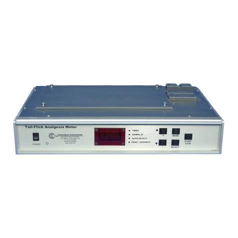
Columbus Instruments CLAMS User manual

CLAMS Hardware Manual
June 1, 2022
1012-0001 v1.01
950 North Hague Avenue
Columbus, Ohio 43204-2121 USA
Sales: sales@colinst.com
Service: servi[email protected]om
Phone: (614) 276-0861
Fax: (614) 276-0529
Toll Free: 1-800-669-5011
http://www.colinst.com


3
CLAMS Hardware Manual 1012-0001 v1.01
Table of Contents
1 –Introduction....................................................................................................................................................... 5
1.1 Overview ....................................................................................................................................................... 5
1.2 Electrical Components .................................................................................................................................. 5
1.2.1 AC Power ................................................................................................................................................ 5
1.2.2 DC Coaxial Connection ........................................................................................................................... 5
1.2.3 Ethernet Cable Connection .................................................................................................................... 6
1.3 Air and Water Connections........................................................................................................................... 6
1.3.1 Nut and Ferrule Fittings ......................................................................................................................... 7
1.3.2 Push-Fit Fittings...................................................................................................................................... 7
1.3.3 Quick-Connect Fittings with Lock........................................................................................................... 8
2 –Computer Setup ................................................................................................................................................ 9
2.1 Minimum Computer Requirements.............................................................................................................. 9
2.2 CI-Bus Hub/Switch Mini ................................................................................................................................ 9
2.3 Connecting the CI-Bus Hub ......................................................................................................................... 11
3 –Oxymax............................................................................................................................................................ 12
3.1 Negative Ventilation Setup ......................................................................................................................... 12
3.1.1 Overview .............................................................................................................................................. 12
3.1.2 Universal Flow Controller..................................................................................................................... 14
3.1.3 Ventilation Pump.................................................................................................................................. 16
3.1.4 Connecting Components...................................................................................................................... 17
3.2 Gas Sensor Chain Setup............................................................................................................................... 21
3.2.1 Gas Sensor Chain Overview.................................................................................................................. 21
3.2.2 Universal Gas Conditioner.................................................................................................................... 22
3.2.3 Filter Columns ...................................................................................................................................... 25
3.2.4 Ammonia Traps .................................................................................................................................... 26
3.2.5 Particle Filters....................................................................................................................................... 27
3.3 Chemical Oxygen Sensor............................................................................................................................. 28
3.3.1 Chemical Oxygen Sensor Specifications............................................................................................... 28
3.3.2 Chemical Oxygen Sensor Replacement................................................................................................ 30
3.4 Zirconia Oxygen Sensor............................................................................................................................... 31
3.4.1 Zirconia Oxygen Sensor Specifications................................................................................................. 31
3.5 Paramagnetic Oxygen Sensor...................................................................................................................... 34

4
CLAMS Hardware Manual 1012-0001 v1.01
3.5.1 Paramagnetic Oxygen Sensor Specifications ....................................................................................... 34
3.6 Chemical Oxygen Sensor Setup................................................................................................................... 36
3.6.1 Placing the Components ...................................................................................................................... 36
3.6.2 Connecting the Components................................................................................................................ 38
3.7 Zirconia Oxygen Sensor Setup..................................................................................................................... 45
3.7.1 Placing the Components ...................................................................................................................... 45
3.7.2 Connecting the Components................................................................................................................ 47
3.8 Paramagnetic Oxygen Sensor Setup ........................................................................................................... 54
3.8.1 Placing the Components ...................................................................................................................... 54
3.8.2 Connecting the Components................................................................................................................ 56
4 –Feeding............................................................................................................................................................ 63
4.1 Feeding Overview........................................................................................................................................ 63
4.2 Mass Scale................................................................................................................................................... 63
4.2.1 Connecting the Mass Scale................................................................................................................... 64
4.3 Load Cells..................................................................................................................................................... 66
4.4 Feeder Assembly......................................................................................................................................... 67
4.4.1 Assembling the Feeder......................................................................................................................... 68
4.4.2 Filling the Feeder with Food................................................................................................................. 70
4.4.3 Disassembling the Feeder Assembly.................................................................................................... 71
5 –Cleaning........................................................................................................................................................... 72

5
CLAMS Hardware Manual 1012-0001 v1.01
1 –Introduction
1.1 Overview
Columbus Instruments’ Comprehensive Lab Animal Monitoring System (CLAMS) is capable of simultaneously
recording a diverse range of measurements from as many as 32 subjects. All the data collection components of
CLAMS connect by the way of the “CI-Bus” technology system. The CI-Bus easily integrates all the data from all
devices for collection by the host computer. Configuration options within each system allow around-the-clock,
automated, non-invasive collection of physiological and behavioral parameters such as activity, food and water
consumption, metabolic performance, temperature, etc. Each CLAMS is built to the client’s specifications;
therefore, no two systems are likely to look or function the same.
This manual serves as a guide for the general setup of the different components available for the CLAMS
system. Not all sections of the manual may pertain to the system you are using. Also, components and parts
are subject to change as improvements and modifications are made. Therefore, the photos and images of
components may not exactly match the ones you have. However, their function and setup in the system
should be similar. Some of the images used for the assembly instructions were not performed on actual CLAMS
shelving for clarity.
1.2 Electrical Components
There are many electrical connections used throughout the CLAMS system. The following details most of the
connections and the correct way to make and check them.
1.2.1 AC Power
It is highly recommended to use an AC power strip with power switch and surge protection for connecting and
protecting all the CLAMS components. A single-source AC power strip also provides a beneficial common
ground between all connected components which helps prevent unintentional ground loops that can occur
when using different AC outlet power sources. Likewise, the power switch can serve as a “master” power
switch that will switch on the power to all the CLAMS components.
The CLAMS warranty does not cover damage due to power surges.
It is also recommended to connect the host computer and CLAMS system to one or more uninterruptible
power supplies (UPS). This can prevent the loss of data during brief power outages and brownouts. Make sure
to use a UPS capable of delivering power to the components that are connected to them. For example, a
1000VA UPS is sufficient for most 8-cage CLAMS systems. Another, separate UPS should be used for the host
computer. Each UPS’s batteries should be replaced every three (3) years to ensure uninterrupted service.
1.2.2 DC Coaxial Connection
The DC Coaxial cable with plugs is typically used to connect low-voltage DC power from an AC-sourced power
supply or inter-connect DC power between various components of the CLAMS system. Common low-voltage
power sources are rated at 5, 12 or 24 volts with varying current capacities for their intended devices.
Improper source voltage and/or overloading the power supply may cause intermitted or faulty operation of
the connected devices.

6
CLAMS Hardware Manual 1012-0001 v1.01
To connect a DC coaxial power plug, fully insert the plug into the cabinet/component jack. In some cases, part
of the outside metallic barrel may be exposed.
The connection is secured by a friction fit. Therefore, be sure to route the power cable as to minimize any
physical tension on the plugs and protect them from being unintentionally pulled from their jacks.
1.2.3 Ethernet Cable Connection
The Ethernet cable connection is used for CI-Bus communication and other electrical connections between
various components of the CLAMS system. It is an 8-pin, 8-conductor, plug to plug cable commonly referred as:
RJ-45, CAT5, CAT5e, network cables, etc. They are found between all the CI-Bus devices and the Optical Activity
sensors. The cable plug incorporates a locking tab which mates to the panel jack to secure the connection.
•To make an ethernet connection, fully insert the cable plug into the panel jack until a “click” is heard.
The plug should not pull free from the jack.
•To remove, simply depress the locking tab and pull the plug free.
1.3 Air and Water Connections
There are many air and water connections used throughout the CLAMS system. The following details most of
them and the correct way to make and check them.

7
CLAMS Hardware Manual 1012-0001 v1.01
1.3.1 Nut and Ferrule Fittings
A nut and ferrule are used to make an air-tight or water-tight connection. These connections are commonly
found between calorimetry and drinking components of the system and cages.
•To make a new nut and ferrule connection: trim the end of the plastic tube with a sharp implement
(tube cutter preferred) leaving the end as square as possible. Ensure there are no frayed edges on the
end.
•Slide the nut and 2-piece ferrule 3cm over the end of the tube as indicated in the diagram below.
•Fully insert and hold the tube (about 1cm) into the flared fitting on the cabinet or cage.
•Slide the nut (and ferrule) to the mating threads of the fitting and finger-tighten until firm.
Only use nylon ferrules, metal ferrules may leak when used with plastic tubing and can
damage metal sipper tubes. Excessive tightening may pinch the tube or damage the fitting.
1.3.2 Push-Fit Fittings
Push-Fit fittings are used to make air-tight connections. They are commonly found near components of the
system that may require frequent maintenance (such as filters) or around components which modify the
operation of the system (such as flow restrictors).
•To make a connection, ensure the end of the tube is smooth with no frayed edges. If required, trim the
end of the plastic tube with a sharp implement (tube cutter preferred) leaving the end as square as
possible.
•Fully insert the tube into the plastic fitting, through the resistance, until it stops (about 1.5cm for most
fittings). The tube should not pull free from the fitting and the locking collar around the tube socket
will travel and rotate with the tube.

8
CLAMS Hardware Manual 1012-0001 v1.01
•To remove the tube from the connector, press and hold the locking collar against the body of the
fitting.
•Now pull the tube free from the fitting.
1.3.3 Quick-Connect Fittings with Lock
Quick-connect fittings with lock are used to make air-tight connections to sources which require intermittent
use. They are commonly installed on the regulators of calibration gas bottles and associated tubing. The
female fitting will need to be installed on the output of the gas regulator. The male plug should already be
connected to a tubing assembly

9
CLAMS Hardware Manual 1012-0001 v1.01
•Using Teflon tape or pipe sealant (which may already have been applied at the factory), thread the
female quick-connect fitting into the output of the pressure regulator (compressed air bottle shown).
Use a 9/16” open-end or crescent wrench to fully tighten.
•When a connection is needed, fully insert the male plug into the female fitting. A spring-like resistance
will be felt, and the integrated locking lever should “click” over the beveled edge of the female fitting,
securing the connection together.
•To remove, simply depress the locking lever and pull the plug free.
2 –Computer Setup
2.1 Minimum Computer Requirements
The host computer is expected to be an IBM-PC compatible running a Windows operating system (XP, Vista, 7,
8.1, 10). It must have a minimum of: 128MB of memory, 1GB of free hard drive space and an free Universal
Serial Bus (USB) port.
2.2 CI-Bus Hub/Switch Mini
The CI-Bus Hub is used to create the interface between the host computer and the CLAMS/Oxymax system. It
connects via a USB port which creates a virtual COM port accessible by the Oxymax software. All

10
CLAMS Hardware Manual 1012-0001 v1.01
communications from the Oxymax software are passed through the CI-Bus Hub to four (4) terminated CI-Bus
ports. By “daisy-chain” fashion, ethernet cables are used to connect devices to the CI-Bus.
The following details the indicators and ports found on the CI-Bus Hub:
•USB: A type B port which connects to a free USB A port on the host computer via a standard USB A-B
cable.
•CI-Bus: Four (4) terminated CI-Bus ports. Each can host up to a minimum of 32 daisy chain connected
CI-Bus devices.
•Power: The IEC line and circle indicator (typically green) which indicates connection to an active USB
port on the host computer.
•Tx: An indicator (typically green) which indicates the host computer is transmitting data to all the CI-
Bus ports.
•Rx: The right-side indicator of each port (typically yellow, four in all) indicates that a CI-Bus device
connected to that port is transmitting data for the host computer.

11
CLAMS Hardware Manual 1012-0001 v1.01
2.3 Connecting the CI-Bus Hub
As the CI-Bus Hub is a USB connected device, it is placed locally near the host computer.
You will also need the following:

12
CLAMS Hardware Manual 1012-0001 v1.01
1 x USB A-B cable
Using the USB A-B cable, insert the A plug into a free USB port on the host computer.
Insert the B plug into the USB port on the CI-Bus Hub. When properly connected, the power indicator should
light.
3 –Oxymax
3.1 Negative Ventilation Setup
3.1.1 Overview
In a negative ventilation system, fresh air travels from the atmosphere into the cage, then through the air
supply line to the Universal Flow Controller (UFC). The air flows of all channels are regulated and passed to the
ventilation pump where it is returned to the atmosphere as illustrated below. One of the channels is selected
for sampling and provided to the Gas Sensor chain.

13
CLAMS Hardware Manual 1012-0001 v1.01
Negative ventilation provides many advantages:
•Small leaks around the openings in the cage lid have a minimal effect upon respiratory gas
concentrations because the intended fresh air is drawn from the immediate atmosphere around the
cage. A fan inside the cage ensures that all the gases are uniformly mixed.
•The sample line used in a positive ventilation system is eliminated as the air supply line ventilates the
cage and supplies the gas sample to the Gas Sensor chain.
The following sub-sections detail the components used in the Negative Ventilation Setup.

14
CLAMS Hardware Manual 1012-0001 v1.01
3.1.2 Universal Flow Controller
The Universal Flow Controller (UFC) provides ventilation for eight cages and one reference cage. It also selects
one of the air supply lines (channels) for gas sampling. The UFC requires an external ventilation pump,
matched in size for the required ventilation rate of all channels.
Universal Flow Controller Specifications:
Mass Flow Range: 0-3L/min (each channel)
Mass Flow Resolution: 0.0003L/min
Physical Size (WxHxD): 30cm x 20cm x 35cm
Physical Weight: 6kg
Power Requirements: 12VDC 3A, 6W

15
CLAMS Hardware Manual 1012-0001 v1.01
Universal Flow Controller Indicators and Ports
•Power –A green light which indicates connection to a source of DC power.
•Data In - A yellow light which indicates the host computer is transmitting data.
•Data Out –A blue light which indicates the UFC is transmitting data.
•Flow Stable - A green light which indicates the status of the measured flow rate of the selected gas
source. ON: The flow rate is at the desired set-point. FLASH: The flow rate does not match or is moving
toward the desired setpoint.
•Input Pressure Stable –A green light which indicates the status of the pressure of the selected gas
source: ON: The input pressure is at the desired set-point. FLASH: The input pressure does not match
the desired set-point for the selected gas source.
•Offset Pressure Stable –A green light which indicates the status of the pressure of all non-selected gas
sources ON: The offset pressure is at the desired set-point. FLASH: The offset pressure does not match
the desired set-point.

16
CLAMS Hardware Manual 1012-0001 v1.01
•CH [1:8] & Ref –The ports for connection of the particle-filtered and restricted 1/4" air supply lines
from each cage in the system plus the reference cage.
•Test Out –The output port for gas sampling.
•Gas Supply –The port for connection to an external air-supply ventilation pump.
•12VDC ⎓3A –DC coaxial jack for connection to a suitable power supply.
•CI-Bus–Two (2) ports for connection to the CI-Bus.
•Power –An indicator (typically green) on the top right corner of the left-most CI-Bus port which
indicates connection to DC power.
•Rx –An indicator (typically yellow) on the top left corner of the right-most CI-Bus port which indicates
the UFC is transmitting data.
•Tx –An indicator (typically green) on the top right corner of the right-most CI-Bus port which indicates
the host computer is transmitting data.
3.1.3 Ventilation Pump
A Ventilation Pump is paired with each Universal Flow Controller (UFC) to provide the vacuum pressure and
flow necessary to ventilate all the air supply lines and cages. Typically, the pump is a HIBLOW, model 40 or 80.
The following details the connections found on the Ventilation Pump:

17
CLAMS Hardware Manual 1012-0001 v1.01
•Vacuum Port - The vacuum source, provided by a push-fit fitting situated in the middle of the left side
of the pump.
•Pressure Port - The exhaust port, provided by a 3/4" NPT MIP situated on bottom corner of the left
side of the pump.
•Power Cord –The power cable situated on the bottom corner of the right side of the pump for
connection to a switched AC power source.
3.1.4 Connecting Components
The components of the Negative Ventilation system are easy to assemble. A working surface that averages
1.0m x 0.5m (40” x 20”) is required which should be situated locally and centrally to each group of up to eight
cages (plus the reference cage). This can be on the bottom shelf of a rack system or on top of a temperature
controlled incubator. The reference and subject cages should already be setup, each with particle filter and
system specific restrictor (refer to the appropriate cage manual, specific to your system) The following details a
typical layout:

18
CLAMS Hardware Manual 1012-0001 v1.01
You will also need the following:
2 x AC outlets from a common-switched source
1 x suitable 12V coaxial DC power supply with AC power cord
1 x ethernet cable
1 x filter assembly for the ventilation pump
Supply of 1/2" OD natural airline.
Supply of 1/4" OD green airline
1 x CI-Bus terminator (for all the UFCs in the system)

19
CLAMS Hardware Manual 1012-0001 v1.01
For each group of cages with UFC and ventilation pump:
•Using an appropriate length of 1/4" green air line, connect each port (Ch[1:8] and Ref) to its associated
cage’s air supply 1/4" union (at the end of the cage restrictor assembly).

20
CLAMS Hardware Manual 1012-0001 v1.01
For proper operation, all channel and reference ports require a particle filter and system
specific flow restrictor.
•Using an appropriate length of 1/2" natural air line, connect the vacuum port of the Ventilation Pump
to the “Gas Supply” port of the UFC.
•Locate the filter assembly for the ventilation pump. It’s primary purpose is to quite the noise of the
pump and typically consists of serially connected filters.
•Thread the up-stream port of the filter assembly onto the output of the pump and hand-tighten.
Table of contents
Other Columbus Instruments Measuring Instrument manuals
Popular Measuring Instrument manuals by other brands

AXIOMA METERING UAB
AXIOMA METERING UAB QALCOSONIC W1 TECHNICAL DESCRIPTION, INSTALLATION MANUAL AND USER GUIDE

TESTO
TESTO 552 instruction manual

Leviton
Leviton VerifEye Series 4100 Installation guides

SMART365
SMART365 SM-06-05030G manual

A.B.Energy
A.B.Energy ABE 1500 user manual

Anritsu
Anritsu VNA Master MS2024B manual

LumaSense technologies
LumaSense technologies IMPAC IGA315-K USB Operation manual

Brigade
Brigade Backsense BS-9000 Installation & operation guide

Rotronic
Rotronic HygroPalm HP23-A user guide

Siemens
Siemens BTC-BR user manual

Stahl
Stahl 8485 Series operating manual

GM INSTRUMENTS
GM INSTRUMENTS ASRA user guide