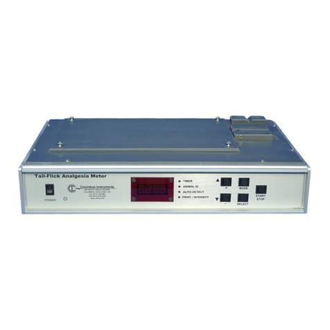
Columbus Instruments 180 C User manual

© <1985-2013> ... Columbus Instruments International
Model 180 C
Instruction Manual


Table of Contents
Foreword 0
Part I Hardware 2
................................................................................................................................... 21 Introduction
................................................................................................................................... 52 Specifications
................................................................................................................................... 53 Installation
................................................................................................................................... 374 Operations
................................................................................................................................... 395 Maintenance
Part II Software 43
................................................................................................................................... 431 Software Introduction
................................................................................................................................... 442 Main Menus
................................................................................................................................... 483 System Properties
................................................................................................................................... 514 System Diagnostics
................................................................................................................................... 535 Calibration
................................................................................................................................... 626 Experiment
................................................................................................................................... 667 Data file format
Part III Quick Reference 67
................................................................................................................................... 671 System Setup Hints
................................................................................................................................... 672 Running an Experiment
Index 0
IContents
I
© <1985-2013> ... Columbus Instruments International

Model 180 C gas analyzer2
© <1985-2013> ... Columbus Instruments International
1Hardware
1.1 Introduction
The 180 C Gas Analyzer is a multi channel gas sampler that is capable of measuring up to 6
gases in up to 80 different gas streams (channels) The system consists of a System Sample
Pump, Expansion Interface and an individual gas sensor for each gas that is measured. The
System Sample Pump contains a micro processor that controls the system and communicates
to the host computer through the RS-232 serial port
System Overview
Multiple gas streams are sequentially multiplexed into the system sample pump through the
expansion interface(s) The system sample pump directs the sample gas the sample drier to
remove the water vapor, this is needed to make accurate gas concentration measurements.
Then the gas is circulated through each individual sensor at a constant flow rate and pressure
to prevent errors caused barometric pressure changes. The model 180C employs a host
computer for data collection, storage and presentation device. The software supplied with the
system allows the user to configure the system for use with a wide variety if gas samples
The following ranges and gases are available
O2
19-21%,0-100$ (user programmable for any range in 0-100%
CO2
0-2000ppm,0-1%,0-3%,10-10% 0-30%,0-100%
CH4
0-1000ppm, 0-1%,0-5%,0-30%,0-100%
H2
0-1000ppm,0-2000ppm
H2S
0-200 ppm
N20
150 ppm
N02
1000 ppm
CO
0-1000 ppm, 0-1%
Principle of operation of the sensors
Paramagnetism: This is a physical property of Oxygen that is shared by very few other gases. It
exhibits a rather unique behavior within a magnetic field and how it interacts with other objects in that
magnetic field. The Paramagnetic Oxygen Sensor consists of a "dumbbell" suspended in a magnetic
field by a very fine wire. Sample gas enters the sensor at a very low flow, under 200 ml/minute. As the
sample gas passes around the dumbbell, the paramagnetic properties of Oxygen pushes the dumbbell
causing it to rotate, which in turn twists the wire suspending it. The rotation of the dumbbell is directly
proportional to the concentration of Oxygen present, the more Oxygen, the stronger the rotation. As the
dumbbell rotates and the wire is twisted, a small mirror bounces a light source to a detector which
tracks the rotation of the dumbbell. A small current is passed through the
wire, which brings the dumbbell back to its original position. The more Oxygen present, the more
current needed to bring the dumbbell back into position. This current is the signal generated from the
sensor.

Hardware 3
© <1985-2013> ... Columbus Instruments International
Electrochemical Fuel Cell: Like the name implies, this sensor is indeed a battery. And just like a
battery, it has a finite life span. The gradual "death" of the cell results in sensor drift (which we account
for at the end of each measurement cycle). We use it for the detection of Oxygen, Hydrogen, Hydrogen
Sulfide, Nitrous Oxide, Carbon Monoxide (2000 ppm), and Sulfur Dioxide. Electrochemical Cells work
by chemically reacting to the respective gas present in the sample. The target gas (Oxygen, for
example) passes by the cell resulting in a chemical reaction which produces an electric current
proportional to the concentration of oxygen in the sample. Electrochemical Fuel Cells consume some
of the target gas during the measurement. Therefore, the amount consumed is taken into
consideration when making calculations and subsequent measurements.

Model 180 C gas analyzer4
© <1985-2013> ... Columbus Instruments International
Non-Dispersive Infrared Detection: This method of measurement is made by simple spectroscopy;
emitting a known amount of a specific wavelength of infra-red light through a sample and recording the
amount absorbed by the sample. We use this method for the detection of Carbon Dioxide, Methane,
and Carbon Monoxide (10%). Each of these compounds absorb a very narrow wavelength range of
infra-red light. Each respective sensor emits the corresponding wavelength of IR light, it passes
through the sample gas, and a detector records how much of the IR light makes it through. This value
is inversely proportional to the concentration of gas in the sample.

Hardware 5
© <1985-2013> ... Columbus Instruments International
1.2 Specifications
Power consumption
180 C system: 100 Watts
Controller / computer: 200 Watts
Physical dimensions
Sample Pump & Sensors: 13" x 11.5" x 12" (33 x 29 x 30 cm)
Expansion Interface: 13" x 11.5" x 7.5" (33 x 29 x 19 cm)
Controller: 17" x 17" x 7" (43 x 43 x 18 cm)
CO2/CH4/H2S Sensor 13" x 11.5 x 4" (33 x 29 x 10 cm)
Paramagnetic O2 Sensor 13" x 11.5 x 7.5" (33 x 29 x 19 cm)
Weight
System Sample Pump & Sensors: 20 Ibs. (9 Kg)
Paramagnetic O2 Sensor: 15 lbs (6.8 Kg)
Electrochemical O2 Sensor 6 lbs (2.7 Kg)
CO2/CH4/H2S Sensor 6 lbs (2.7 Kg)
Expansion Interface: 12 Ibs. (5.5 Kg)
Gas Flow Rate
100 cc/min 1 - 500 cc/min (500 cc/min standard)
1.3 Installation
If a computer is not included with the system, refer to the computer manuals for instructions
on installing and configuring the components.
AC Power Filtering and Battery Backup
It is highly recommended to use an AC power filter/surge suppresser with the system to
protect all instrumentation. The 180 C system warranty does not cover damage due to
power surges.
It is also a good idea to connect the system (including the computer) to an un-
interruptable power supply. This will prevent the interruption of experiments and loss of data
during brief power outages, and brownouts. Make sure that the un-interruptable power supply
delivers a minimum of 500 watts of electrical power.
Tubing Connections
Two types of tubing connection are used on the system. The connections on the back of the
sensors, dryers, and System Sample pump employ a metal nut and 2 piece plastic ferrule. The
other type of connection is a "quick connect" type fitting and is used on the expansion unit and
flask assemblies.

Model 180 C gas analyzer6
© <1985-2013> ... Columbus Instruments International
To make a connection using the nut and ferrule, slide the nut onto the end of the tubing and
then slide on the two-part ferrule. Allow 0.25 cm of tubing to stick out beyond the end of the
ferrule. Screw the nut on to the port finger-tight. Then tighten it another 1 /4 turn using a
wrench.
Be careful not to over-tighten these connections. Excessive tightening may result
in a pinched tube or damage to the fittings.
To make a tubing connection using the "quick connect" type fittings, simply press the tubing
into the fitting. Tubing should slide approximately 1.75 cm inside the connection and resist
dislodging by pulling. To disconnect these fittings, hold the collar around the tubing firmly
against the fitting while pulling the tubing.
If excessive leakage occurs with these fittings,
most likely the end of the tubing is worn. Cutting a 1 cm piece off the end of the tubing
should restore the seal. Be sure to use a sharp knife when cutting the tubing for these
fittings to ensure a good seal.
The 1/8" pieces of tubing are supplied in separate bags labeled
"Sensor Tubing', "Drier tubing", and "Expansion Interface tubing" (if present). Refer to the
following drawing when making the System Sample Pump, Sensor and Expansion Interface
tubing connections.

Hardware 7
© <1985-2013> ... Columbus Instruments International
Connect the air filter to the rear of the sample pump as shown below. These protect the
instrument against contamination by particles which could damage the instrument.
Connect the large drier filled with Soda Lime (white granules) as shown in the drawing. The
bottom fitting (the sealed end) of the large drier connects to the fitting labeled "Nitrogen" on
the back of the System Sample cabinet with 1/4" tubing.
Connection of standard O2/CO2/CH4 sensors
The shortest of the three pieces of tubing labeled "Sensor Tubing" is used to connect the
"Sensor Out" fitting on the Carbon Dioxide Sensor to the "Sensor In" fitting on the Oxygen
Sensor. The medium-length piece of tubing links the "Sensor Out" fitting of the Oxygen
Sensor and the "Sensor In" fitting of the System Sample Pump. If an additional sensor is
installed another piece of tubing is used to connect the oxygen sensor's "Sensor Out" fitting to
the "Sensor In" fitting on the additional sensor. Finally, the long piece of tubing is used to
connect the "Sensor In" fitting of the Carbon Dioxide sensor and the "Sensor Out" fitting of

Model 180 C gas analyzer8
© <1985-2013> ... Columbus Instruments International
the System Sample Pump.

Hardware 9
© <1985-2013> ... Columbus Instruments International
Sample drier connections
All systems are equipped with a sample drier the sample drier removes the water vapor for
accurate analysis.
Connect as shown with the 1/8" tubing

Model 180 C gas analyzer10
© <1985-2013> ... Columbus Instruments International
Connect the drying column(S) to the sample drier
Connection of toxic gas sensors
Some systems are equipped with what are referred to as toxic gas sensors. The H2, H2S, CO,
NO2, SO2, NO, NO2 sensors are all toxic gas sensors. They have the special requirement that
the sample gas cannot be completely dry. This is because the sensors are electrochemical cells
and if the cell dries out it will stop working. Therefore the toxic gas sensors are connected
before the sample drier.
The proper connection is shown below.
Connect the connector labeled "output to drier" on the front of the sample pump to the sensor
in connector on the toxic gas sensor (note the sensor is turned around for showing the
connection normally it would be facing forward)

Hardware 11
© <1985-2013> ... Columbus Instruments International
Then connect any additional toxic gas sensors in series if the system is equipped with more
than one

Model 180 C gas analyzer12
© <1985-2013> ... Columbus Instruments International
Then connect the sensor out fitting (of the last sensor for systems with more than 1 toxic gas
sensors)

Hardware 13
© <1985-2013> ... Columbus Instruments International
Then connect the "sample gas out" fitting on the sample drier to the "input from drier" fitting
on the system sample pump.
If the system does not include an Expansion Interface, connect the sampling line to the
System Sample Pump.
Be sure to use a filter to protect the sample pump from contamination.

Model 180 C gas analyzer14
© <1985-2013> ... Columbus Instruments International
If the system includes an Expansion Interface, connected it to the System Sample Pump using
a single piece of tubing

Hardware 15
© <1985-2013> ... Columbus Instruments International
If the system includes more than one Expansion Interface, a small manifold, "T" fitting, or
union cross fitting will also be included. Connect the manifold to the system sample pump as
shown in the drawing below:

Model 180 C gas analyzer16
© <1985-2013> ... Columbus Instruments International
Cable Connections
Pictures below depict the proper cable configuration. To connect the cables, find the 25
conductor cables with the two female ends. If the system is configured with two sensors then
there should be a total of three 25-pin cables. If the system is equipped with additional sensors
then there should be an additional cable per sensor. These cables connect to the connectors
labeled "Sensors" which are located on the rear of the sensor and system sample pump
cabinets. The first cable should connect the system sample pump to the first sensor.

Hardware 17
© <1985-2013> ... Columbus Instruments International
Each additional sensor connects in series with the 25 pin cables

Model 180 C gas analyzer18
© <1985-2013> ... Columbus Instruments International
Locate the smaller 9-pin cable with a male and female connectors. This cable is used to
connect the system sample pump's serial communication port to the computers serial
communication port. The cable is a direct cable connection. Note: on some computers the
serial communications port is equipped with a 25-pin connect in place of the 9-pin connector.
If this is the case a 9 to 25 pin adapter will be needed. This adapter can be purchased at any
local computer store or it can be obtained from Columbus Instruments.
Use the remaining 25 pin cables with male connectors to connect the expansion units to the
system sample pump. Like the sensor cables, there will be one cable per expansion unit. The
first expansion unit is connected directly to the system sample pump's connector labeled
"Expansion Unit". Additional expansion units are connected in series to one another through
the additional 25-pin cables.
Table of contents
Other Columbus Instruments Measuring Instrument manuals
Popular Measuring Instrument manuals by other brands

AXIOMA METERING UAB
AXIOMA METERING UAB QALCOSONIC W1 TECHNICAL DESCRIPTION, INSTALLATION MANUAL AND USER GUIDE

TESTO
TESTO 552 instruction manual

Leviton
Leviton VerifEye Series 4100 Installation guides

SMART365
SMART365 SM-06-05030G manual

A.B.Energy
A.B.Energy ABE 1500 user manual

Anritsu
Anritsu VNA Master MS2024B manual

LumaSense technologies
LumaSense technologies IMPAC IGA315-K USB Operation manual

Brigade
Brigade Backsense BS-9000 Installation & operation guide

Rotronic
Rotronic HygroPalm HP23-A user guide

Siemens
Siemens BTC-BR user manual

Stahl
Stahl 8485 Series operating manual

GM INSTRUMENTS
GM INSTRUMENTS ASRA user guide