BMT 964 User manual

BMT MESSTECHNIK GMBH
BMT MESSTECHNIK GMBH, Stahnsdorf, Germany. Tel. +49 - 3329 - 696 77 - 0, fax +49 - 3329 - 696 77 - 29
OSTI Ozone Systems & Technology International, Inc., USA Tel. +1 - 831 - 649 11 41, fax +1 - 831 - 649 11 51
OZONE ANALYZER BMT 964
Manual
Rev. 04/2021

OZONE ANALYZER BMT 964 Manual, Rev. 04/2021
2
OZONE ANALYZER BMT 964
This manual describes the standard version BMT 964. For the versions BMT 964 BT,
BMT 964 C, OFF-GAS System, BMT 964 AQ and BMT 964 RD, also refer to the according
Appendices at the end of this manual !
Contents
1 General Description 5
2 Cautions & Warnings 5
3 Installation and Power Connection 7
Photometers and Dirt 8
4 Output and Control Terminals 9
Analog Outputs 9
Binary Input 9
Binary Outputs 10
Error Relay 10
Serial Interface (RS-232): 10
5 Switching On the Instrument 11
6 Front Panel Operation 11
Changing Parameters 12
Zeroing the Instrument from the Front Panel 13
The Menu View Parameters 13
The Menu Set Parameters 14
Units 16
Ozone 16
Pressure 17
Alarms 17
High-Alarm 17
Low-Alarm 18
Input/Output 19
Simulate Analog Out 19
RS-232 19
Gas Parameters 19
Molecular Weight 19
Time/Date 19
Time 19
Date Format 19
Date 20
Other Parameters 20
Autozero Interval 20
Alarm Beep 20
Reset Parameters 20

OZONE ANALYZER BMT 964 Manual, Rev. 04/2021
3
7 The Serial Interface 21
User-Mode 21
Link-Mode 22
8 Zeroing the BMT 964 23
Automatic Zeroing with Control of Purge Gas 23
9 Use of the Limit-Alarms 25
10 Error Handling and Early Warnings 25
Lamp Low Warning 25
Lamp Low Error 26
Lamp Off Error 26
Lamp High Error 26
Cuvette Dirty Warning 26
Cuvette Dirty Error 26
Overpressure 27
Overrange 27
EEPROMError 27
11 Event- and Error-Log 27
12 The Program BMT 964 Link 28
13 Maintenance 29
14 Troubleshooting 31
15 Specifications 32
Appendix A: Link-Mode Commands 33
Appendix B: Bench Top Version BMT 964 BT 37
General Description 37
Operation 37
Appendix C: Cabinet Version BMT 964C 39
General description 39
Ozone Destruct 40
Operation 41
Maintenance 41
Dimensions 42
Electric connections: 42
Appendix D: OZONE-IN-OFF-GAS System 43
General Overview 43
Off-Gas Cabinet BMT 964OG 44
Sample Gas Pump SGP 5 44
Sample Gas Cooler/Dryer DH5 45
Operation 46
Maintenance 46

OZONE ANALYZER BMT 964 Manual, Rev. 04/2021
4
Electric Connections 47
Appendix E: DI Water Version BMT 964 AQ 48
General Description 48
Electric connections 50
Appendix F: Remote Display BMT 964 RD 51
General Description 51
Operation 51
Appendix G: MODBUS RTU Communication 52
Physical Connection 52
Set Communication Parameters 53
MODBUS Operation 53
Function Code 1 – Read Single Coil 54
Function Code 3 – Read Holding Registers 55
Function Code 5 – Write Single Coil 55
Function Code 8 – Diagnostics 56
Function Code 16 (10h) – Write multiple Registers 56

OZONE ANALYZER BMT 964 Manual, Rev. 04/2021
5
1 General Description
The OZONE ANALYZER BMT 964 is a microprocessor-based dual beam photometer
(UV 254 nm) for measuring the ozone content in air or oxygen.
To evaluate the ozone content in the sample gas the OZONE ANALYZER BMT 964 measures
the UV radiation in the measurement channel, the UV radiation in the reference channel, the
temperature and the pressure in the cuvette.
The ozone concentration is displayed in either percent weight of ozone (%wt/wt), grams of
ozone per normal cubic meter of sample gas (g/Nm3) or ppmv (AQ: g/m3 or ppm) on a 16-
character alphanumeric display. The concentration unit can be changed during operation. Addi-
tional modifiable parameters are among others :
Unit of pressure display (selectable: bar, psi, Torr, MPa)
Alarm parameters (high/low threshold, alarm latching, audible, opening or closing relays)
Nature of the carrier gas: air or oxygen (incl. PSA)
Date and time
RS-232 interface parameters
These parameters can be set with the three pushbuttons on the front panel as well as by connect-
ing the serial interface to a Windows-PC running the program BMT 964 Link, which is supplied
with each instrument. Another way of configuring the instrument is to use the so-called Link
Mode via the serial interface.
The instrument has a built-in clock with calendar, which is used to provide time stamps for an
Event-Log (48 entries, e.g. zeroing, alarms) and an Error-Log (16 entries, e.g. Overrange, Cuvette
Dirty). These logs can be read out and printed via the serial interface with the mentioned pro-
gram BMT 964 Link.
2 Cautions & Warnings
The exclamation point within an equilateral triangle is intended to alert the
user to the presence of important operating and maintenance (servicing) in-
structions in the literature accompanying the instrument.
The lightning flash with arrowhead symbol, within an equilateral triangle is
intended to alert the user to the presence of uninsulated “dangerous voltage”
within the product’s enclosure that may be of sufficient magnitude to consti-
tute a risk of electric shock to persons.
The “Caution, hot surface” symbol indicates that the marked item may be
hot and should not be touched.
Warning: Ozone is a highly toxic gas. The ozone concentrations measured by the OZONE
ANALYZER BMT 964 are above the lethal limit. Appropriate safety devices (ozone detectors)
should be used.

OZONE ANALYZER BMT 964 Manual, Rev. 04/2021
6
Warning: This product relies on the building's installation for short-circuit (overcurrent) protec-
tion. Ensure that a fuse or circuit breaker no larger than 15 A at 120 VAC (10 A at 240 VAC) is
used on the phase conductor.
The installation of the power connector has to be made by a person aquainted with the safety
problems involved. Do not connect or disconnect the voltage-carrying connector!
Warning: Do not use this instrument in a oxygen-enriched atmosphere (fire hazard)! Follow
recommended oxygen handling practices.
Warning: Do not apply more than 2.5 barg gas pressure to the instrument! The maximum for
the Off-Gas version BMT 964 OG is 1 barg.
Warning: Make sure that the flow rate is not higher than 0.8 l/min, and the red ruby ball inside
the flow meter is not at its upper white stop!
Warning: Disconnect electrical power before opening the cabinet door.
Warning: Before opening the sample gas filter make sure that the sample line does not contain
ozone gas under an overpressure.
Caution: If the generator feed gas contains nitrogen, connect a tube to the outlet of the ozone
destruct to lead away the vent gas. Corrosive nitric acid will be formed when vent gas comes in
contact with the moist ambient air.
Caution: The UV radiation power output of the UV lamp is less than 1 Watt. Avoid dismantling
of the instrument with mains power applied. The lamp contains 5 milligrams of mercury. Mercu-
ry is a poison. Dispose lamp at a waste disposal place which is qualified to handle mercury con-
taining lamps. If you cannot find a respective place, return the lamp to BMT.
Précaution:
Avertissement
: L’ozone est un gaz à forte toxicité. Les concentrations d’ozone mesurées à l’aide de l’analyseur
d’ozone BMT 964 vont au-delà de la limite mortelle. C’est pourquoi il convient d’utiliser une technique de sécurité
adéquate (détecteur d’ozone).
Attention
: Le montage et le branchement au secteur devront être exécutés par une personne spécialement formée
à cet effet. Le branchement et le débranchement sous tension sont interdits !
Attention
: Ce produit est soumis à l’emploi d’un fusible de surintensité dans le bâtiment. Vérifiez que le fusible
de la phase utilisée ne dépasse pas 15 A pour 120 VCA (10 A pour 240 VCA).
Attention : Ne pas utiliser cet instrument dans une atmosphère enrichie en oxygène (risque d'incendie)! Suivez les
recommandations associées à l''utilisation de l'oxygène
Avertissement
: La pression du gaz à mesurer ne doit pas dépasser 2,5 bar de surpression.
Avertissement
: Le débit ne doit pas dépasser 0,8 l/min ! La boule rouge du débitmètre ne doit pas toucher la
butée blanche !
Avertissement
: Débranchez avant d’ouvrir la porte.
Avertissement
: Avant d’ouvrir le filtre du gaz à mesurer, assurez-vous que dans la conduite du gaz à mesurer
il n’y a pas d’ozone sous pression.
OZONE ANALYZER BMT 964 Manual, Rev. 04/2021
7
3 Installation and Power Connection
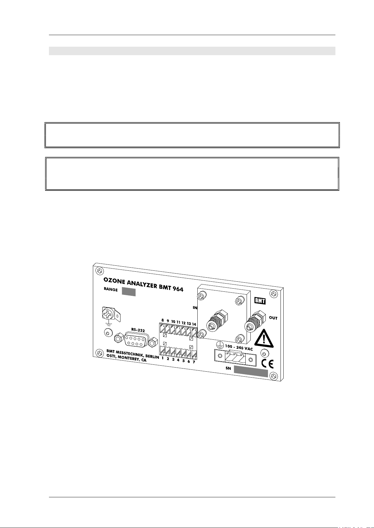
The OZONE ANALYZER BMT 964 is a 144 x 72 mm front panel instrument (according to
DIN 43700). The mounting cut-out should be 139 x 67 mm (W x H). Depth is approx. 230 mm.
The power line voltage may be 100 to 240 VAC (50 or 60 Hz). All necessary parts needed for
installation are supplied with the instrument (e.g. power and signal connectors, mounting brack-
ets, a tool for opening the sample gas filter holder). The serial port cable is a standard RS-232
type and is supplied with every analyser (also with the different models in the Appendix).
The installation of the power connector has to be made by a person aquainted with the
safety problems involved. Do not connect or disconnect the voltage-carrying connector!
Warning: This product relies on the building's installation for short-circuit (overcurrent) protec-
tion. Ensure that a fuse or circuit breaker no larger than 15 A at 120 VAC (10 A at 240 VAC) is
used on the phase conductor.
The power receptacle or the mains socket-outlet the instrument is connected to should be easily
accessible for fast interruption of power, or other means for switching off power should be pro-
vided.
Optionally the instrument is available in a low voltage version with a voltage range from
12 to 36 VDC (max. power consumption is 15 W). The backplane is shown here:
For the sample gas connection 3 x 5 mm PTFE tubing (or FEP tubing 1/8" x 3/16") should be
used (which we will supply on request). The sample gas has to be connected via the sample gas
filter ("IN"). The time lag of the concentration measurement depends on
a) the flow rate of the sample gas,
b) the length of the tubing to the analyzer,
c) the cross section of the tubing (we recommend tubing 3 x 5 mm, not more!),
d) the time lag of the analyzer itself. At the recommended flow rate of .2 to 1 l/min time lag will
be 2 to 0.4 s with a 3 x 5 mm tubing length of 1 m.
OZONE ANALYZER BMT 964 Manual, Rev. 04/2021
8
Photometers and Dirt
Using 254 nm UV radiation the ozone photometer "looks" through the gas, or the water, in
which the ozone is contained. It looks via two cuvette windows made of fused quartz. When
these windows become dirty the instrument cannot distinguish between a reduction of the UV
radiation by the ozone present in the cuvette - and the reduction by dirty cuvette windows. The
most important rule for operating an ozone photometer is: "The only real enemy of an ozone
photometer is dirt!"
When measuring ozone, namely in an industrial environment, it really pays off to thoroughly pro-
tect the ozone analyser from any dirt which might be contained in the ozone sample gas.
BMT ozone analysers for gaseous ozone are equipped with particle filters containing a replacea-
ble filter insert. The filter inserts should from time to time be checked for dirt (see page 29,
Maintenance), and be replaced on a regular basis depending on the degree of particle content of
the sample gas.
The ozone gas coming from most types of ozone generators contains more or less nitrogen ox-
ides because the oxygen feed gas contains nitrogen, inadvertently, or intentionally. Namely medi-
um sized and big generators are operated with high nitrogen doping. When such generators are
serviced without disconnecting the ozone analyser the danger of dirt getting into the analyser is
particularly high.
Caution: High concentration of nitrogen oxides in the sample gas must be avoided. If this could
occur e.g. during generator service, sample gas flow must be stopped!
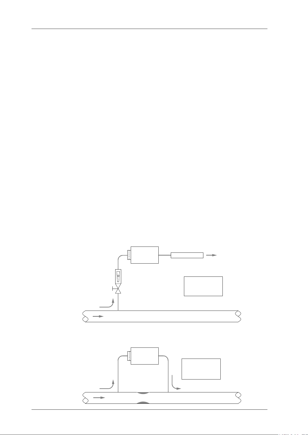
The following two drawings show two possible configurations:
"bleed" flow
0.1 - 1l/ min
system flow system pressure > a mbient pressure
measurement ta kes pla ce
at ambient pressure
"bleed" flow ra te depends
on system pressure
VENT mode
throttle
rota meter
vent to
ambient
ozone destruct
(low flow resistance)
OZ ON E
AN ALYZER
system flow any system pressure
bypass flow
0.1 - 1 l/ min
measurement ta kes pla ce
at system pressure
bypa ss flow rate depends
on system flow ra te
defined
flow resistance
PRESS mode
OZ ON E
AN ALYZER

OZONE ANALYZER BMT 964 Manual, Rev. 04/2021
9
4 Output and Control Terminals
All signal leads should be shielded. The shield should be connected to the ground terminal ( )
of the instrument via an 1/4'' FASTON connector. The following table describes the signal con-
nector and is also printed onto the top of the standard instrument.
Analog Outputs
The output signals are updated about 25 times per second.
The voltage output is an isolated voltage signal 0 to 10 V, proportional to the concentration (ac-
tually this signal swings down to about -0.25 V below zero). Input resistance of the load should
be higher than 1 k.
The current output is an isolated current signal 4 to 20 mA, proportional to concentration (with
an offset of 4 mA). Input resistance of the load should be less than 600 (optional 1350 ).
The current output provides the energy for the curent loop.
Attention: The current output must not be connected to an external power supply !
Binary Input
The binary input is used to trigger the ZERO function of the OZONE ANALYZER BMT 964.
By applying a voltage of typ. +24 VDC between pin 11 (+) und pin 10 (-) for about 0.5 seconds
the instrument will be zeroed. The ZERO function may be triggered only after complete
purging of the cuvette with filtered air or oxygen (purging for at least 10 seconds plus delay
of the input tubing)!
OZON E AN AL Y ZER BMT 964
BMT MESSTECHN IK, BERLIN phone + + 49 30 - 801 85 95 fax + + 49 30 - 802 23 62
OSTI, MON TEREY, CA phone + + 1 - 831 - 6491141 fax + + 1 - 831 - 6491151
OUTPUT AN D CON TROL TERMIN ALS
AN ALOG OUTPUTS:
I sola ted
7 Concentration 0- 10V
6 GN D (10 V)
5 Concentration 4- 20 mA
4 GN D (4- 20 mA)
ERROR RELAY:
Isola ted, Um a x = 30 V DC, Im a x = 1 A
1
3
RELAY CON TACTS:
OUTPUTS:
Isola ted, Um a x = 28 V, Ima x = 0.5 A
8 Out Common
9 Lamp Low
12 High Ala rm
13 Low Alarm
14 Cuvette Dirty
2 Purge
IN PUT:
Isola ted, U = 2 4 VDC, I = 18 mA
10 Zero GN D
11 Set to Zero (no O3)
USE SHIELDED CABLE CON N ECT SH IELD TO
ALWAYS CON SULT THE MAN UAL
Open on Error
OZONE ANALYZER BMT 964 Manual, Rev. 04/2021
10
Input current at the binary input is approx. 18 mA. The input is protected against voltages with
wrong polarity.
Binary Outputs
Pin Function Description see page
9 Lamp Low Opens when the lamp becomes too weak 25
12 High Alarm Opens or closes if concentration is above a certain threshold 25
13 Low Alarm Opens or closes if concentration is below a certain threshold 25
14 Cuvette Dirty Opens when a dirty cuvette is detected 26
2 Purge Contact for external pump / solenoid valve 23
The binary outputs are relay contacts, which are used to signal errors and alarms. An additional
contact is used for the selection of purge gas during automatic zeroing. The common contact of
all binary output relays is on pin 8. The following outputs are available:
The binary output contacts can switch a max. voltage of 28 V and a max. current of 0.5 A. The
binary outputs can be used as "high-side switches" (voltage applied to pin 8) or "low-side switch-
es" (pin 8 connected to ground). Further explanations of the different output functions can be
found on the pages mentioned.
Error Relay
The error output is an SPST relay contact. In order to prevent a broken wire from remaining
undetected, the contact has been designed as opening on error (normally closed closed if there
is no error), see page 25 for more details on error handling. The contact may be loaded
with 30V/1A. The error output is isolated to the binary outputs mentioned above.
In the warm-up phase and if the instrument is powered off, the error relay is in the error state.
Serial Interface (RS-232):
The bidirectional isolated serial interface is used for communication with a PC or other automa-
tion components in an industrial environment.
Connection:
Pin Function Description
2 TxD Data sent
3 RxD Data received
5 GND RS-232 ground
Note: The RS-232 GND and isolated analog outputs GND are connected!
The data format used is eight bits, one stopbit, no parity (8N1). See page 19 for configuration of
the interface.

OZONE ANALYZER BMT 964 Manual, Rev. 04/2021
11
5 Switching On the Instrument
After application of the mains voltage the instrument will display the following:
BMT964 VX.XX
VX.XX denotes the software version. Then concentration and pressure range will be shown, e.g.:
R:200 g/Nm3
PR: 2.5 bar
This display is followed by a warmup period, the length of which is being determined by the state
of the lamp. During warmup the Error Relay is switched to error. All other relay contacts are
open. The analog outputs put out 10 V and 20 mA respectively. The serial interface (see page 19)
puts out max. concentration, actual pressure and the code for the warmup-state. The time left
for change into normal operating mode is displayed and counted down in second intervals. The
time period between switching on and normal operating mode can last between 40 s and 120 s.
During this time the front panel keys and the zero-input are deactivated.
6 Front Panel Operation
The front panel consists of a 16-character alphanumeric display (LCD with red backlight illumi-
nation) and three pushbuttons. The display will be updated every 0.3 s.
ZERO / ENTER
OZON E ANAL Y ZER BMT 964
BMT MESSTECHN IK, BERLIN
OSTI, MO N TEREY
SCROLL / SETBACK
The pushbuttons can be used to perform the following operations:
Switch to pressure display
Zero the BMT 964
View parameters
Change the parameters
The following diagram shows the functions of the main menu:

OZONE ANALYZER BMT 964 Manual, Rev. 04/2021
12
Concen-
tration Pressure View
Parameters
Set
Parameters
Main Menu
ZERO/
ENTER
SCROLL
BACK
Zeroing:
Sure?
Zeroing
Press Scroll for
at least 2 s
PIN-Protection
Expressions printed bold in the following sections of text always relate to the contents of the
instrument menus.
The button SCROLL / SET moves to the right within the menu, the key ZERO / ENTER
downwards and the button BACK moves upwards. The SCROLL action will continue on the left
side, once it has reached the right side of the diagram. This is also valid for the later explained
menus View Parameters and Set Parameters.
From now on, when relating to the multi-functional keys SCROLL / SET and ZERO / ENTER
only the function meant in the context will be mentioned.
Starting with Concentration pressing the button SCROLL will lead to Pressure. Here the pres-
sure inside the cuvette is displayed and updated every 0.3 s. One further push on SCROLL dis-
plays View Parameters. After pressing ENTER the parameters can be viewed, but they cannot
be changed.
Changing Parameters
If in the menu position View Parameters the button SCROLL is pushed briefly, the instrument
resumes display of the ozone concentration (Menu position Concentration).
In order to move from View Parameters to Set Parameters the SCROLL button has to be
held down for at least 2 seconds.
The menu Set Parameters is used to change properties of the instrument, like units, alarms etc.
In order to protect the instrument and the components connected to it from unqualified hand-
ling, the above mentioned procedure has to be performed. In addition, the instrument configura-
tion can be protected by a 4-digit PIN. This PIN is factory set to 0000, which means that after
pressing the SCROLL button for 2 s, properties can be changed freely. The Windows software
BMT 964 Link can be used to change this PIN to any other 4-digit number. If the PIN is differ-
ent from 0000, pressing the SCROLL key for 2 s will lead to the display of:
Enter PIN 0000:
Only the correct PIN will allow entry to Set Parameters, any other number will lead back to the
display of ozone concentration.
View Parameters and Set Parameters will be described on the following pages. During viewing
and setting of parameters the instrument continues measuring, i.e. new measurement results are
sent out on the analog outputs and the serial interface continuously.
OZONE ANALYZER BMT 964 Manual, Rev. 04/2021
13
Zeroing the Instrument from the Front Panel
If ozone concentration is shown on the display and the ZERO button is pushed, the instrument
displays the question:
Zeroing: Are you sure?
Due to the fact that zeroing with ozone would lead to wrong measurement results, this question
gives the user the opportunity to stop. This can be done by pressing the button BACK. In case
there is really no ozone present in the cuvette, the ZERO button may be pressed again, after
which zeroing starts. Further information about zeroing the BMT 964 can be found on page 23.
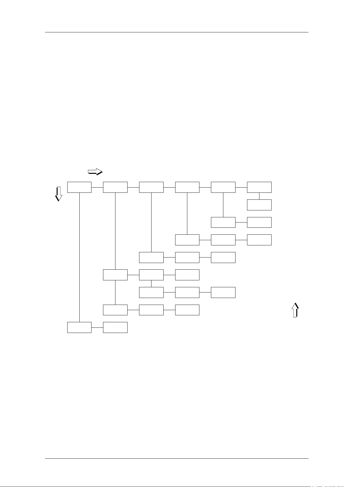
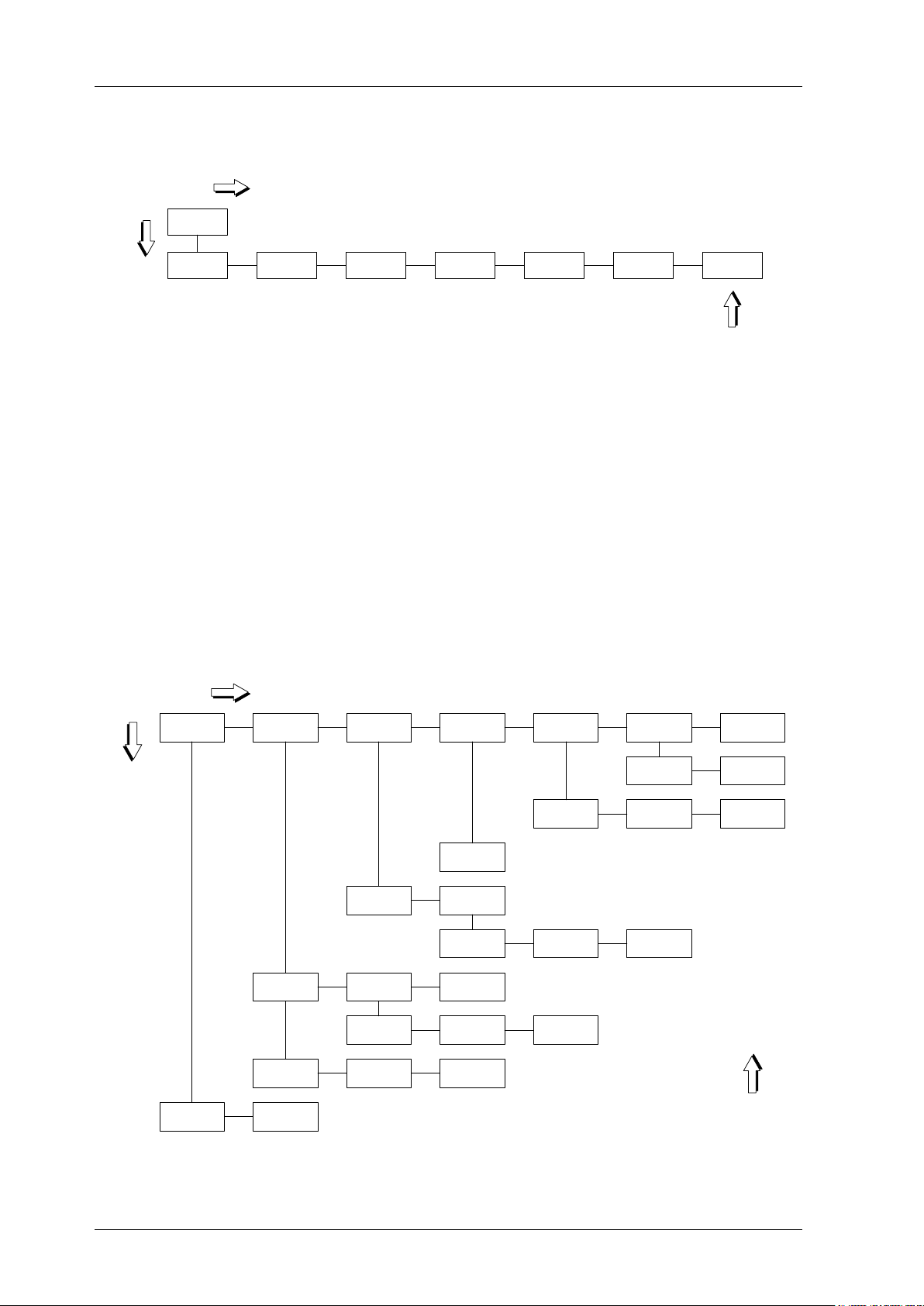
The Menu View Parameters
In the menu View Parameters the configuration of the BMT 964 can be viewed, but it cannot
be changed.
Units Alarms RS-232 Gas
Parameters Time/Date Other Param.
See next
Page
Time Date
Norm.
Temperature
Norm.
Pressure Mol. Weight
Baudrate Timed/Polled Time Interval
High Alarm Low Alarm Relays Open/
Close
Enable/
Disable Threshold Latching
Enable/
Disable Threshold Latching
Ozone Pressure
Menu View ParametersSCROLL
ENTER
BACK
The following parameters are shown:
Units
Unit of ozone concentration
Unit of pressure
Alarms
Activation, thresholds, latching, closing or opening of Alarm Relays
RS-232
Baud rate, periodic transmission or polling, time interval of periodic transmission
Gas-Parameters
nature of the carrier gas: air or oxygen (incl. PSA oxygen)
Time / Date
OZONE ANALYZER BMT 964 Manual, Rev. 04/2021
14
The meaning of these parameters is explained in greater detail on the following pages. An addi-
tional point in the menu View Parameters is Other Parameters:
Operating
Hours
Autozero
Interval
Alarm Beep
On/Off Range Pressure
Range Serial No.
Menu Other Parameters
Cuvette
Status
Other Param.
ENTER
SCROLL
BACK
Autozero Interval and Alarm Beep On/Off are also explained on page 20. The other elements
of the menu cannot be changed.
Explanations:
Range: max. ozone concentration
Pressure Range: max. pressure
Serial No.: the serial number
Cuvette Status: shows dirtyness of the cuvette in %
Operating Hours: since calibration
The Menu Set Parameters
Menu Set Parameters
Units Alarms Input/Output Gas
Parameters Time/Date Other
Parameters
Autozero
Time Alarm Beep
Time Date Format Date
Oxygen/Air
Simulate
Analog Out RS-232
Baudrate Timed/Polled Time Interval
High Alarm Low Alarm Relays Open/
Close
Enable/
Disable Threshold Latching
Enable/
Disable Threshold Latching
Ozone Pressure
ENTER
SCROLL
BACK
Reset
Parameters

OZONE ANALYZER BMT 964 Manual, Rev. 04/2021
15
In order to move from View Parameters to Set Parameters the SCROLL button has to be
held down for at least 2 seconds.
The configuration of the BMT 964 can be changed here. The diagram shows the selectable pa-
rameters. In order to change a setting, the ENTER button has to be pressed. Logical variables, as
e.g. Enabled/Disabled are configured with the SET button. Numerical values as e.g. Thresh-
old are changed digit by digit. To change a digit, the SET button is used. The digit to be changed
is marked by a cursor beneath it. In order to move to the next digit, the ENTER button has to be
pressed. The procedure can be stopped at any time by pushing the BACK button. After complete
setting of the parameter the ENTER button has to be pressed again, the display
Saving...
appears for a short time and the parameter is saved. To leave the menu press the back button
several times.
This is an example for changing a logical variable: the unit of ozone concentration shall be
changed from g/Nm3 to %wt/wt:
Button Display
0.0 g/Nm3
SCROLL 1.013 bar
SCROLL View Parameters
SCROLL (>2 s) Set Parameters
ENTER Set Units
ENTER Set Ozone Unit
ENTER Ozone: g/Nm3
SET Ozone: %wt/wt
ENTER Saving...
Ozone: %wt/wt
BACK Set Ozone Unit
BACK Set Units
BACK Set Parameters
BACK 0.00 %wt/wt
One more example: the numerical parameter High Alarm - Threshold (determines the thresh-
old, above which a High Alarm occurs) shall be changed from 75 g/Nm3 to 90 g/Nm3.
Button Display
0.00 g/Nm3
SCROLL 1.013 bar
SCROLL View Parameters
SCROLL (> 2s) Set Parameters
ENTER Set Units

OZONE ANALYZER BMT 964 Manual, Rev. 04/2021
16
SCROLL Set Alarms
ENTER Set High Alarm
ENTER Enable/Disable
SCROLL Set Hi-Threshold
ENTER Hi:075.0 g/Nm3
ENTER Hi:075.0 g/Nm3
SET Hi:085.0 g/Nm3
SET Hi:095.0 g/Nm3
ENTER Hi:095.0 g/Nm3
SET Hi:096.0 g/Nm3
SET Hi:097.0 g/Nm3
SET Hi:098.0 g/Nm3
SET Hi:099.0 g/Nm3
SET Hi:090.0 g/Nm3
ENTER Hi:090.0 g/Nm3
ENTER Saving...
Hi:090.0 g/Nm3
BACK Set Hi-Threshold
BACK Set High Alarm
BACK Set Alarms
BACK Set Parameters
BACK 0.00 g/Nm3
On the following pages you can find a detailed description of all configurable parameters. Change
of one parameter may lead to the automatic change of other parameters. The stored parameter
information is not lost when the instrument is switched off.
Units
Ozone
This will set the unit of ozone concentration. You can choose between:
g/Nm3
% wt/wt
ppmv
g/m3 (AQ)
ppm (AQ)
If the concentration unit is changed the range will change, too:
g/Nm3 % wt/wt ppmv Range-ID
2.000 0.1500 1000 1
5.000 0.3500 2500 2
10.00 0.7000 5000 3
20.00 1.500 10000 4

OZONE ANALYZER BMT 964 Manual, Rev. 04/2021
17
g/Nm3 % wt/wt ppmv Range-ID
50.00 3.500 25000 5
100.0 7.000 50000 6
150.0 11.00 75000 7
200.0 14.00 100000 8
300.0 20.00 150000 9
400.0 26.00 200000 10
0.750 0.0600 375.0 11
15.00 1.100 7500 12
500.0 31.00 250000 13
600.0 37.00 300000 14
0.500 0.0400 250.0 15
Please bear in mind, that there is a non-linear relationship between g/Nm3 and
ppmv on one side and %wt/wt on the other side. Also, the full range concentra-
tions are not exactly the same upon switching, as the range limits are rounded val-
ues.
Accordingly, the analog outputs may change, when the ozone concentration unit
is changed.
Furthermore, the thresholds of High & Low Alarm are recalculated automatically.
For a complete list of available ranges, please refer to the order sheet.
Pressure
The unit of absolute pressure shown on the display can be changed from bar to
psi, Torr or MPa. Here are some examples for recalculation of pressure range
when changing the unit:
bar psi Torr MPa
1.15 16.68 863 0.115
1.5 21,76 1125 0.150
2.0 29.02 1500 0.200
2.5 36.27 1875 0.250
3.0 43.52 2250 0.300
3.5 50.78 2625 0.350
4.0 58.03 3000 0.400
For a complete list of available ranges, please refer to the order sheet.
Alarms
High-Alarm
This alarm occurs if Enable/Disable is activated and the limit stored under
Threshold is exceeded. In case Relays Open/Close is set to Relays Closing, the
High-Alarm-Relay closes (default), otherwise it opens. At the same time a High-

OZONE ANALYZER BMT 964 Manual, Rev. 04/2021
18
Alarm-Event is entered into the Event-Log. The display alternates between the
measurement result and the message
High Alarm!
If Alarm Beep is activated, there is also an acoustic signal, which may be stopped
using the BACK key, if the front panel menu is on its basic level. The BACK but-
ton does not clear a latched alarm, though.
If ozone concentration falls below Threshold – 0.002 x range (hysteresis) the
alarm state is ended if Latching is set to Not-Latching. The High-Alarm-Relay
falls back into its normal state, the error message and the acoustic signal disap-
pear. The end of the alarm state is entered into the Event-Log.
In case Latching is activated, the alarm will not go away until it is acknowledged
by pressing the ENTER button, even if concentration falls below the mentioned
threshold. The end of alarm will be entered into the Event-Log when the button
is pushed. Also, the button is free for initiating zeroing again.
Low-Alarm
This alarm occurs if Enable/Disable is activated and concentration is below the
limit stored under Threshold. In case Relays Open/Close is set to Relays Clos-
ing, the Low-Alarm-Relay closes (default), otherwise it opens. At the same time a
Low-Alarm-Event is entered into the Event-Log. The display alternates between
the measurement result and the message
Low Alarm!
If Alarm Beep is activated, there is also an acoustic signal, which may be stopped
using the BACK key, if the front panel menu is on its basic level. The BACK but-
ton does not clear a latched alarm, though.
If ozone concentration rises above Threshold + 0.002 x range (hysteresis) the
alarm state is ended if Latching is set to Not-Latching. The Low-Alarm-Relay
falls back into its normal state, the error message and the acoustic signal disap-
pear. The end of the alarm state is entered into the Event-Log.
In case Latching is activated, the alarm will not go away until it is acknowledged
by pressing the ENTER button, even if concentration rises above the mentioned
threshold. The end of alarm will be entered into the Event-Log when the button
is pushed. Also, the button is free for initiating zeroing again.
Relays Open/Close:
This variable decides if the alarm relays will open or close if an alarm occurs. Re-
lays Closing (default) leads to closing contacts upon reaching the alarm threshold.
This menu item influences both alarm relays at the same time.

OZONE ANALYZER BMT 964 Manual, Rev. 04/2021
19
Input/Output
Simulate Analog Out
For test purposes both analog outputs can be set to their max. (10 V / 20 mA) re-
spectively min. (0 V / 4 mA) values. With the program BMT 964 Link any voltage
and current can be put out.
RS-232
This menu item is used to configure the serial interface. The User-Baud rate can
be set to one of the following values:
2400 Baud
4800 Baud
9600 Baud (default)
19200 Baud
38400 Baud
The setting of Timed/Polled decides, if the output of data on the serial interface
is done automatically in a certain time interval (Timed) or if a block of data is sent
only on request (character '?', without CR). If the operating mode is set to Timed,
a data block is sent every Time Interval . Minimum interval is 1 s, max. interval is
99 s. A detailed description of the serial interface can be found on page 10.
Gas Parameters
Warning: A change of this parameter will influence measurement results!
Molecular Weight
When using the BMT 964 it is important to give the instrument information about
the carrier gas. Two different carrier gases can be chosen:
Oxygen, or oxygen from PSA, molecular weight 31.9988
Air (molecular weight 29.0)
If the customer does not specify a particular molecular weight when ordering, it
will be set to oxygen.
Time/Date
Time
Here the time of day is set in the format hh:mm:ss.
Date Format
Display of date can be switched from European (DD.MM.YY) to American
(MM/DD/YY) notation.

OZONE ANALYZER BMT 964 Manual, Rev. 04/2021
20
Date
During entry the date will be constantly tested on conformance to the calender
rules, so it is not possible e.g. to enter the date 29.02.01. In order to make this test
possible, first the year, then the month and then the day has to be set.
Other Parameters
Autozero Interval
This variable determines, if and in which time interval (hours) the instrument will
perform an (fully) automatic zeroing cycle. If set to zero, there will be no automat-
ic zeroing.
Caution: In case the instrument is configured for automatic zeroing care must be
taken to supply the purge gas (oxygen or filtered air). The instrument may either
be equipped with an external or Internal Purge Unit (solenoid valve and air pump
with particle filter, available as an option), or some other means of switching the
purge gas supply via the PURGE relay contact has to be provided (see also page
23).
The time interval between two automatic zeroing cycles can be set between 1 and
99 hours. If the instrument is set to automatic zeroing one additional zero cycle is
performed 15 min after switching on. A zero triggered manually, via RS-232 or
the binary input will reset the interval timer.
Alarm Beep
If this item is set to Enabled, the BMT 964 emits an acoustic signal during Low-
or High-Alarms. This beeper may be stopped using the BACK button, if the front
panel menu is on ist basic level.
Reset Parameters
This will set all Parameters described above back to factory settings. When press-
ing ENTER, the instrument displays
Are you sure?
If ENTER is pressed again, parameters are set as described in the following table:
Parameter Setting
Ozone Unit g/Nm3
Pressure Unit bar
High Alarm Limit 80 % of Range
High Alarm enabled No
High Alarm latched No
Low Alarm Limit 40 % of Range
Low alarm enabled No
Low Alarm latched No
Other manuals for 964
1
Table of contents
Other BMT Measuring Instrument manuals


