Comba Telecom RX-1839 User manual

1
18
80
00
0M
MH
HZ
Z
D
DI
IG
GI
IT
TA
AL
L
B
BA
AN
ND
D
S
SE
EL
LE
EC
CT
TI
IV
VE
E
R
RE
EP
PE
EA
AT
TE
ER
R
USER MANUAL
RX-1839 QE: 1-0-0
Comba Telecom Ltd.
RX-1839

____________________________________________________________________________________________
_
The information contained herein is the responsibility of and is approved by the
following, to whom all enquiries should be directed in the first instance:
This is an unpublished work the copyright in which vests in Comba International
("Comba"). All rights reserved.
The information contained herein is confidential and the property of Comba and is
supplied without liability for errors or omissions. No part may be reproduced,
disclosed or used except as authorised by contract or other written permission.
The copyright and the foregoing restriction on reproduction and use extend to all
media in which the information may be embodied.

INSTALLATION GUIDE FOR RX-1839
ENU STATUS : 1-0-0
Copyright - refer to title page
Page 3
0.1 CONTENTS
Section
Page
0.1 CONTENTS....................................................................................................................................... 3
0.2 INDEX TO FIGURES AND TABLES............................................................................................. 5
0.3 HISTORY........................................................................................................................................... 6
0.4 GLOSSARY OF TERMS................................................................................................................. 7
0.5 SAFETY NOTICES AND ADMONISHMENTS............................................................................. 8
1GENERAL INFORMATION............................................................................................................. 9
2EQUIPMENT DESCRIPTION....................................................................................................... 10
2.1 FUNCTIONAL BLOCK DIAGRAM............................................................................................... 10
2.2 EQUIPMENT LAYOUT.................................................................................................................. 11
2.3 EQUIPMENT CONSTITUTION.................................................................................................... 11
2.4 KIT OF PARTS ............................................................................................................................... 12
3INSTALLATION.............................................................................................................................. 13
3.1 WARNINGS AND ALERTS........................................................................................................... 13
3.2 SITE PLANNING CONSIDERATIONS........................................................................................ 14
3.2.1 SITE PLANNING ............................................................................................................................ 14
3.2.2 INSTALLATION CHECKLIST....................................................................................................... 15
3.3 INSTALLATION PROCEDURES ................................................................................................. 16
3.3.1 GOODS INWARDS INSPECTION .............................................................................................. 16
3.3.2 TOOLS............................................................................................................................................. 16
3.3.3 PREPARATION.............................................................................................................................. 16
3.3.4 WALL MOUNTING......................................................................................................................... 17
3.3.5 POLE MOUNTING OF MOUNTING RACK................................................................................ 18
3.3.6 DRIP-LOOP..................................................................................................................................... 18
3.4 EQUIPMENT CONNECTORS...................................................................................................... 19
3.5 EQUIPMENT CONNECTIONS..................................................................................................... 21
3.5.1 GROUNDING CONNECTION...................................................................................................... 21
3.5.2 RF CABLE CONNECTION ........................................................................................................... 21
3.5.3 EXTERNAL ALARM CONNECTION........................................................................................... 21
3.5.4 MODEM ANTENNA CONNECTION............................................................................................ 21
3.5.5 BACK-UP MONITORING LI-ION BATTERY CONNECTION.................................................. 22
3.5.6 PHYSICAL CONNECTION TO OMT PC.................................................................................... 22
4COMMISSIONING ......................................................................................................................... 23
4.1 PRE-COMMISSIONING TASKS.................................................................................................. 23
4.2 MCU LED INDICATOR AND RESET BUTTON......................................................................... 23
4.3 COMMISSIONING PROCEDURE............................................................................................... 24
5OMT.................................................................................................................................................. 26
5.1 LOCAL AND REMOTE CONNECTION TO OMT...................................................................... 26
5.2 OMT LOGIN.................................................................................................................................... 26
5.3 OMT CONTROL PANEL............................................................................................................... 27
5.4 LOCAL CONNETION TO OMT.................................................................................................... 27
5.5 REMOTE CONNECTION TO OMT............................................................................................. 29
5.6 OMT CONFIGURATION............................................................................................................... 29
5.7 RF PARAMETER ........................................................................................................................... 30
5.7.1 SWITCH........................................................................................................................................... 30
5.7.2 CHANNEL NO. ............................................................................................................................... 31
5.7.3 ATT................................................................................................................................................... 32
5.7.4 ALARM THRESHOLD................................................................................................................... 32
5.7.5 POWER........................................................................................................................................... 33

INSTALLATION GUIDE FOR RX-1839
ENU STATUS : 1-0-0
Copyright - refer to title page
Page 4
5.7.6GAIN................................................................................................................................................. 34
5.7.7 TEMPERATURE............................................................................................................................. 34
5.7.8 ALARM CONFIG............................................................................................................................ 34
5.7.9 MISCELLANEOUS......................................................................................................................... 35
5.8 ALARM INFO.................................................................................................................................. 35
5.9 PROPERTY INFO.......................................................................................................................... 37
5.9.1 EQUIPMENT ID.............................................................................................................................. 37
5.9.2 FIRMWARE INFO.......................................................................................................................... 37
5.9.3 EQUIPMENT INFO........................................................................................................................ 38
5.9.4 SITE LOCATION............................................................................................................................ 38
5.9.5 SYSTEM CLOCK............................................................................................................................ 38
5.9.6 COMM. CONFIG............................................................................................................................ 39
5.9.7 TRIGGER REPORT....................................................................................................................... 40
5.9.8 UPDATE INFO................................................................................................................................ 40
6MAINTENANCE.............................................................................................................................. 41
7APPENDICES................................................................................................................................. 42
7.1 APPENDIX A: TOOLS................................................................................................................... 42
7.2 APPENDIX B: RMA (RETURN MATERIAL AUTHORIZATION) FORM ................................ 43

INSTALLATION GUIDE FOR RX-1839
ENU STATUS : 1-0-0
Copyright - refer to title page
Page 5
0.2 INDEX TO FIGURES AND TABLES
Figure 1: Front, Side and Bottom Views of the RX-1839 Enclosure............................................................ 9
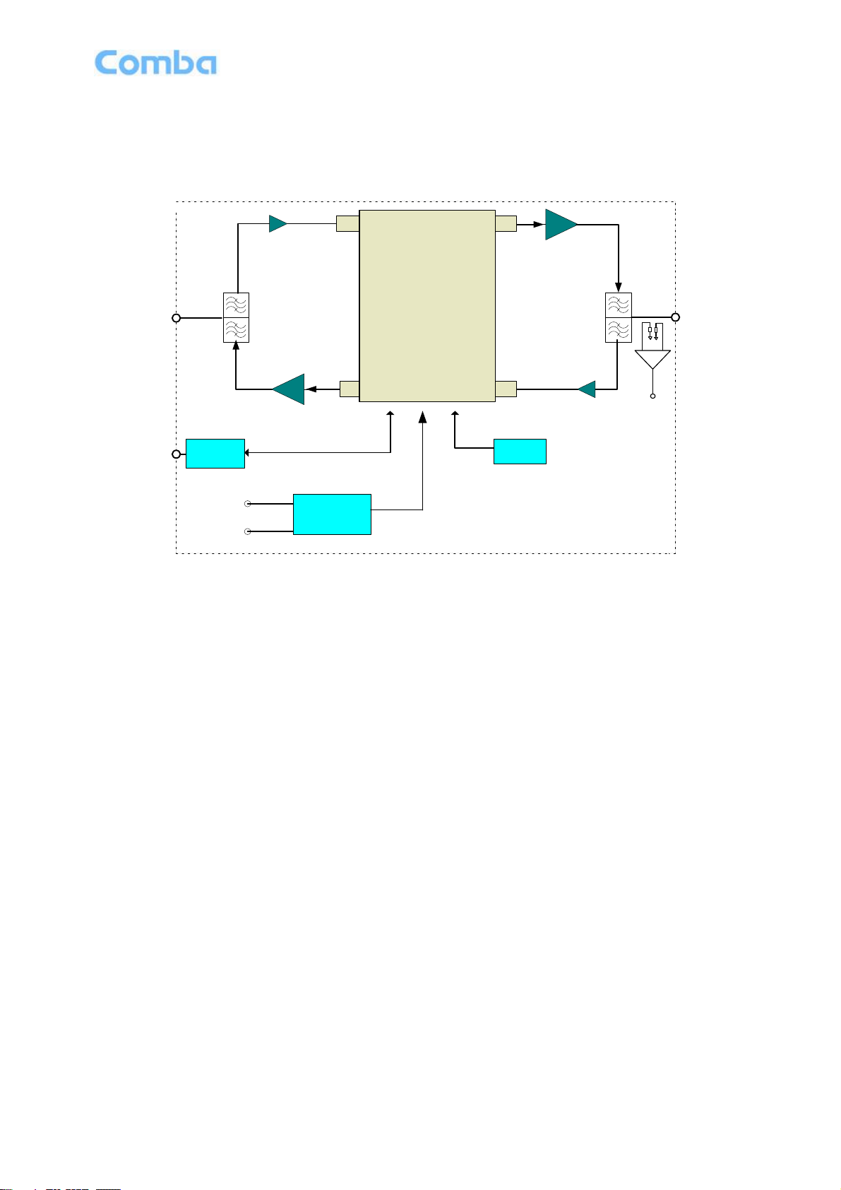
Figure 2: RX-1839 Functional Block Diagram............................................................................................ 10
Figure 3: Layout of the RX-1839................................................................................................................ 11
Figure 4: Mounting Rack Overview............................................................................................................ 16
Figure 5: Wall Mounting............................................................................................................................. 17
Figure 6: Pole Mounting Overview............................................................................................................. 18
Figure 7: Equipment Connectors ............................................................................................................... 19
Figure 8: Maintenance Window Diagram................................................................................................... 20
Figure 9 Pins Allocation for “EXT_ALM” Port for RU ................................................................................ 21
Figure 10: Maintenance Window Internal Layout...................................................................................... 22
Figure 11: OMT Connection without Chassis Open................................................................................... 22
Figure 12: MCU Board LEDs...................................................................................................................... 23
Figure 13: OMT Login ................................................................................................................................ 26
Figure 14: OMT 5.0 Control Panel ............................................................................................................. 27
Figure 15: PC Protocol Setting................................................................................................................... 27
Figure 16: Connection Type....................................................................................................................... 28
Figure 17: Remote Connection .................................................................................................................. 29
Figure 18: OMT Main Window ................................................................................................................... 29
Figure 19: Auto Read................................................................................................................................. 30
Figure 20: Switch........................................................................................................................................ 30
Figure 21: Channel No............................................................................................................................... 31
Figure 22: Frequency Calculator................................................................................................................ 31
Figure 23: The Protective Frequency Edge Interval................................................................................... 32
Figure 24: ATT ........................................................................................................................................... 32
Figure 25: Alarm Threshold........................................................................................................................ 33
Figure 26: Power........................................................................................................................................ 33
Figure 27: Gain........................................................................................................................................... 34
Figure 28: Temperature ............................................................................................................................. 34
Figure 29: Alarm Config. ............................................................................................................................ 34
Figure 30: Miscellaneous ........................................................................................................................... 35
Figure 31: Master Alarm............................................................................................................................. 35
Figure 32: Channel Alarm .......................................................................................................................... 36
Figure 33: External Alarm........................................................................................................................... 36
Figure 34: Equipment ID ............................................................................................................................ 37
Figure 35: Firmware Info............................................................................................................................ 37
Figure 36: Equipment Info.......................................................................................................................... 38
Figure 37: Site Location ............................................................................................................................. 38
Figure 38: System Clock ............................................................................................................................ 38
Figure 39: Comm. Config........................................................................................................................... 39
Figure 40: Trigger Report........................................................................................................................... 40
Figure 41: Update Info................................................................................................................................ 40
Table 1: Equipment KOP............................................................................................................................ 12
Table 2: Equipment Connectors................................................................................................................. 19
Table 3: Pin Definition of “EXT_ALM” Port for RU ..................................................................................... 21
Table 4: LED Indicators.............................................................................................................................. 23
Table 5: Commissioning Task Explanation................................................................................................ 25
Table 6: IP Setting Quick Lookup Table..................................................................................................... 28
Table 7: Equipment ID Parameter.............................................................................................................. 37
Table 8: Comm. Config. Parameter ........................................................................................................... 39

INSTALLATION GUIDE FOR RX-1839
ENU STATUS : 1-0-0
Copyright - refer to title page
Page 6
0.3 HISTORY
Change No.
ENU
Details Of Change
1
1-0-0
This manual first created and issued in Jan 2013.

INSTALLATION GUIDE FOR RX-1839
ENU STATUS : 1-0-0
Copyright - refer to title page
Page 7
0.4 GLOSSARY OF TERMS
Abbreviation
Definition
ALC
Automatic Level Control
ATT
Attenuator
BTS
Base Transceiver Station
CH
Channel
CSA
Cross Sectional Area
dB
Decibel
dBm
Decibels relative to 1 milliwatt
DL
Downlink
DT
Donor Terminal
DPX
Duplexer
FS
Frequency Selection
GSM
Global Standard for Mobile Communication
Hz
Hertz
ID
Identification
IF
Intermediate Frequency
LNA
Low Noise Amplifier
LOS
Line-of-Sight
MCU
Main Control Unit
MHz
Megahertz
MT
Mobile Terminal
MTBF
Mean Time Between Failures
NF
Noise Figure
OMC
Operation & Maintenance Center
OMT
Operation & Maintenance Terminal
PA
Power Amplifier
PLL
Phase Locked Loop
PSU
Power Supply Unit
RF
Radio Frequency
SIM
Subscriber Identification Module
SMA
Sub-Miniature A Connector
SMS
Short Message Service
UL
Uplink
VAC
Volts Alternating Current
VDC
Volts Direct Current
VSWR
Voltage Standing Wave Ratio

INSTALLATION GUIDE FOR RX-1839
ENU STATUS : 1-0-0
Copyright - refer to title page
Page 8
0.5 SAFETY NOTICES AND ADMONISHMENTS
This document contains safety notices in accordance with appropriate standards. In the interests of
conformity with the territory standards for the country concerned, the equivalent territorial admonishments
are also shown.
Any installation, adjustment, maintenance and repair of the equipment must only be carried out by trained,
authorized personnel. At all times, personnel must comply with any safety notices and instructions.
Specific hazards are indicated by symbol labels on or near the affected parts of the equipment. The labels
conform to international standards, are triangular in shape, and are colored black on a yellow background.
An informative text label may accompany the symbol label.
Hazard labeling is supplemented by safety notices in the appropriate equipment manual. These notices
contain additional information on the nature of the hazard and may also specify precautions.
Warning Notices:
These draw the attention of personnel to hazards that may cause death or injury to the operator or others.
Examples of use are cases of high voltage, laser emission, toxic substances, point of high temperature, etc.
Alert Notices:
These draw the attention of personnel to hazards that maycause damage to the equipment. An example of
use is the case of static electricity hazard.
Caution notices may also be used in the handbook to draw attention to matters that do not constitute a risk
of causing damage to the equipment but where there is a possibility of seriously impairing its performance,
e.g. bymishandlingor gross maladjustment. Warnings and Cautions within the main text do not incorporate
labels and may be in shortened form.
CAUTION: danger of explosion if battery is incorrectly replaced. Replace only with the same or equivalent
type.
End of Section

INSTALLATION GUIDE FOR RX-1839
ENU STATUS : 1-0-0
Copyright - refer to title page
Page 9
1 GENERAL INFORMATION
The RX-1839 1800MHz Digital Wireless Repeater (hereinafter called “RX-1839”) is designed for 1800MHz
network. It can wireless transmit, two-way amplify BTS uplink and downlink signals and enlarge coverage
range. Digital band selective technologyeffectivelyamplifies the desired BTS signals and provides superior
out-of-band rejection, avoid cell interference and improve call quality.
Main Features
Wideband digital processing technology, instant operation bandwidth reaches 60MHz.
It supports four wideband channels; each channel can turn off separately. Operation band is
0.2MHz-25MHz for GSM or 10, 15, 20MHz for LTE adjustable.
High power bandwidth linear PA ensures signals no distortion amplification.
The system gain is compensated automatically according to the temperature variation within the
enclosure, which ensures stable operation under ambient temperature.
Has off-line isolation testing, downlink VSWR alarm, downlink input filed intensity and output power
testing function, which is convenient for installation and commissioning.
Supports multi-band expansion, convenient for configuration and upgrade.
Monitoring master unit software remote download function enables remote software upgrade.
Local Operation and Maintenance Terminal (OMT): operating status and parameters can be set or
monitored by OMT PC locally.
Operation Maintenance Center (OMC): system working parameters and communication configuration
can be set or inquired remotely through the build-in GSM modem. If alarm is generated, the equipment
will dial up to OMC automatically in the mode of datalink.
Build-in Li-ion battery ensures that alarm information can automatically report to OMC in case of
equipment power failure.
Designed for all weather outdoor installation –waterproof, damp-proof and Omni-sealed.
The following figure shows the enclosure of the RX-1839.
214
300
430 164
Figure 1: Front, Side and Bottom Views of the RX-1839 Enclosure
End of Section

INSTALLATION GUIDE FOR RX-1839
ENU STATUS : 1-0-0
Copyright - refer to title page
Page 10
2 EQUIPMENT DESCRIPTION
2.1 FUNCTIONAL BLOCK DIAGRAM
DL PA
UL PA
MODEM
DT MT
DT Port
Duplexer MT Port Duplexer
Li-ion
Battery
PSU
AC 100V-240V
MODEM
Antenna
Port
LNA
LNA
Digital Integrated
Module
DLin DLout
ULinULout
VSWR
Testing
Figure 2: RX-1839 Functional Block Diagram
In the downlink, the BTS signals are received by donor antenna of the repeater. After the duplexer, the
signals are sent to the LNA module for pre-amplification and digital RF integrated module for digital filtering
and frequency conversion. Then the DL signals will be sent to downlink PA to amplify power and filter via
duplexer. After amplification, the signals are transmitted at the MT port to the service antenna.
In the uplink, the mobile signals are received by the service antenna. After the MT port integrated duplexer,
the signals are sent to the LNA, integrated module for digital filtering, then to PA for power amplification and
to duplexer. After that, the uplink signals are sent to the donor antenna for transmission back to the BTS.

INSTALLATION GUIDE FOR RX-1839
ENU STATUS : 1-0-0
Copyright - refer to title page
Page 11
2.2 EQUIPMENT LAYOUT
Shown below is the internal layout of the RX-1839.
Modem
PSU
DL PA
Door Open Switch
MT Port Integrated
Duplexer
DT Port
Integrated
Duplexer
Li-ion Battery
Surge Arrestor
Digital Integrated Module
MT
DT
RS-485 AC OUT Power
EXT_ALM
MODEM ANT
UL PA
ALC
Vgs 1
Vgs 2
RF IN
RF OUT
Figure 3: Layout of the RX-1839
2.3 EQUIPMENT CONSTITUTION
The typical RX-1839 unit consists of the following components:
Power Amplifier (PA): It fulfils power amplification in both UL and DL branches.
Main Control Unit (MCU): The MCU is used to monitor and control the operation of the repeater. It also
provides the communication interface for remote control and indication. LED indicators provide the
operation status of the MCU.
Integrated Duplexer: The DPX is located towards the DT and MT terminals and permits the uplink and
downlink signals to share a common antenna.
Digital Integrated Module: Consists of Power Conversion module, RF module, digital process module and
monitoring module. Power Conversion module converts +28V DC voltage in to +9VJK and +9VRF. +9VJK,
+9VRF are supplied to monitoring unit and RF unit in integrated module separately. RF module amplifies
and converts the RF signal to IF signal. Digital process module converts the IF signal into baseband signal
via AD conversion and extraction, filtering. After that, IF signal will be amplified and converted to RF signal
by RF module for RF filtering and amplification. Monitoring module monitors and controls the system
parameters and is the interface of both remote monitoring and local commissioning.
Power Supply Unit (PSU): The PSU converts the input voltage into a stable DC to provide power for the
internal functional modules and to charge the internal Li-ion battery.
Surge Arrestor: The AC Mains surge arrestor is mounted next to the PSU and has three connections: VAC
Live, Neutral and Ground. This provides protection to the PSU. It is assumed that the antenna system will
have ample lightning protection.
Note: When the equipment is DC powered, no surge arrestor is required.

INSTALLATION GUIDE FOR RX-1839
ENU STATUS : 1-0-0
Copyright - refer to title page
Page 12
Li-ion Battery: Provides power to the Main Control Unit to send alarm signals in the event of power failure
Modem: The modem is used for remote control and monitors, and for alarm transmission from the repeater
back to the OMC. Only master unit has modem, slave unit remote monitor and control via RS485.
2.4 KIT OF PARTS
Table 1: Equipment KOP
Product Identifier
Description
Quantity
Mounting Rack
RX-21232-5801
1
Power Supply Cable
4m
1
CPC Connector
X14J7P (for external alarm)
1
Masonry Bolt
M10×110
4
Omni-directional Antenna
XD-WCDMA
1
Commissioning Cable
2m, RJ45
1
U Bolt
M10 x 85 x 110
2
T-Shaped Pentagon Key Wrench
N/A
1
Factory Test Report
N/A
1
OMT
OMT software on CD-Rom.
1
End of Section

INSTALLATION GUIDE FOR RX-1839
ENU STATUS : 1-0-0
Copyright - refer to title page
Page 13
3 INSTALLATION
3.1 WARNINGS AND ALERTS
Radio Frequency Energies
There may be situations, particularly for workplace environments near high-powered RF sources, where
recommended limits for safe exposure of human beings to RF energy could be exceeded. In such cases,
restrictive measures or actions may be necessary to ensure the safe use of RF energy.
High Voltage
The equipment has been designed and constructed to prevent, as far as reasonably, practicable danger.
Any work activity on or near equipment involving installation, operation or maintenance must be, as far as
reasonably, free from danger.
Where there is a risk of damage to electrical systems involving adverse weather, extreme temperatures,
wet, corrosive or dirty conditions, flammable or explosive atmospheres, the system must be suitably
installed to prevent danger.
Protective Earthing
Equipment provided for the purpose of protecting individuals from electrical risk must be suitable for the
purpose and properly maintained and used.
Handling Precautions
This covers a range of activities including lifting, lowering, pushing, pulling, carrying, moving, holding or
restraining an object, animal or person from the equipment. It also covers activities that require the use of
force or effort, such as pulling a lever, or operating power tools.
Where some of the abovementioned activities are required, the equipment must be handled with care to
avoid being damaged.
Electrostatic Discharge (ESD)
Observe standard precautions for handling ESD-sensitive devices. Assume that all solid-state electronic
devices are ESD-sensitive. Ensure the use of a grounded wrist strap or equivalent while working with
ESD-sensitive devices. Transport, store, and handle ESD-sensitive devices in static-safe environments.

INSTALLATION GUIDE FOR RX-1839
ENU STATUS : 1-0-0
Copyright - refer to title page
Page 14
3.2 SITE PLANNING CONSIDERATIONS
3.2.1 SITE PLANNING
Site Considerations
Outdoor equipment are designed to be waterproof, rainproof, and with snow protection. Temporary
protection should be taken when the equipment enclosure is opened for installation or maintenance in an
outdoor environment. The equipment must not be opened for installation or maintenance in bad weather
(e.g. gale, storm rainfall, extreme temperatures and high humidity)
Installation Location
Mounting surface shall be capable of supporting the weight of the equipment.
In order to avoid electromagnetic interference, a proper mounting location must be selected to minimize
interference from electromagnetic sources such as large electrical equipment.
Environmental
Humidity has an adverse effect on the reliability of the equipment. It is recommended to install the
equipment in locations having stable temperature and unrestricted air-flow.
The installation location for the product should be well ventilated. The equipment has been designed to
operate at the temperature range and humidity level as stated in the product specifications in the datasheet.
Direct sun light exposure to the equipment should be avoided. Provide additional shelter if necessary.
Power Supply
The power supplyunit (PSU) provides power toall modules within the equipment. Depending on the product
variant, it is recommended that the PSU operates on a dedicated circuit breaker or fused circuit.
Grounding Requirement
Verify that the equipment has been well grounded. This includes antennas and all cables connected to the
system. Ensure lightning protection for the antennas is properly grounded.
Cable Routing
Depending on equipment configuration, a varietyof types of cables are required. Where applicable, ensure
cables are properly routed and secured so that they are not damaged.
Manual Handling
During transportation and installation, take necessary handling precautions to avoid potential physical injury
to the installation personnel and the equipment.

INSTALLATION GUIDE FOR RX-1839
ENU STATUS : 1-0-0
Copyright - refer to title page
Page 15
3.2.2 INSTALLATION CHECKLIST
Working space available for installation and maintenance for each mounting arrangement. Ensure
unrestricted airflow.
Ensure earthing point is within reach of the ground wire.
Ensure a power source is within reach of the power cord and the power source has sufficient capacity.
Where appropriate, ensure unused RF connectors are terminated.
Do not locate the equipment near large transformers or motors that may cause electromagnetic
interference.
Reduce signal loss in feeder cable by minimizing the length and number of RF connections.
Ensure VSWR of antennas system < 1.5:1.
Ensure equipment will be operated within the stated environment (see datasheet)
Observe handling of all cables to prevent damage.
Donor antenna should have a narrow beamwidth and positioned in line-of-sight (LOS) to donor BTS site
so that the donor signal level is maximized. This allows the use of minimum gain to achieve the
maximum DL output power. The UL gain is typically set lower than or equal to the DL gain to minimize
noise interference to the donor BTS
Service antenna should be selected based on the type of service area, e.g., indoor antenna for indoor
application, and panel antenna for outdoor application.

INSTALLATION GUIDE FOR RX-1839
ENU STATUS : 1-0-0
Copyright - refer to title page
Page 16
3.3 INSTALLATION PROCEDURES
3.3.1 GOODS INWARDS INSPECTION
1. Verify the number of packages received against the packing list.
2. Check all packages for external damage; report any external damage to the shipping courier. If there is
damage, a shipping agent should be present before unpacking and inspecting the contents because
damage caused during transit is the responsibility of the agent.
3. Open and check each package against the packing list. If any items are missing, please contact
Comba.
4. Do not remove items from antistatic packing until ready for installation. If damage is discovered at the
time of installation, contact the shipping agent.
3.3.2 TOOLS
See Appendix A for a full list of the recommended tools required for installation and maintenance.
3.3.3 PREPARATION
Wall mounting with the masonry bolts supplied, which make use of the outer holes.
Pole Mounting with the clamp kit supplied, which make use of the inner holes.
85
200
295
270
330
80
62
814
Figure 4: Mounting Rack Overview
The mounting rack is pre-installed with the equipment during shipment. Follow the following steps to
separate the mounting rack from the equipment before commencing wall or pole mounting:
1. Use Allen key to remove all four hex socket bolts at the corners of the enclosure to open the door.
2. Unscrew four hex bolts (M8x20mm) at four corners of the enclosure to remove the mounting rack.

INSTALLATION GUIDE FOR RX-1839
ENU STATUS : 1-0-0
Copyright - refer to title page
Page 17
3.3.4 WALL MOUNTING
Drill four holes on the wall using the position of four holes on the mounting rack as a guide. Fix the
mounting rack to the wall using four masonry bolts (M10x110mm).
Lift the enclosure onto the mounting rack and screw hex bolts (M8x20mm) to secure the enclosure to the
mounting rack.
After local commissioning, close the door, tighten the four pentagon socket bolts at four corners of the
door with the Allen key and lock the door.
Enclosure
M10X110 Masonry Bolt
M8X20 Hex Bolt
Mounting Rack
Figure 5: Wall Mounting

INSTALLATION GUIDE FOR RX-1839
ENU STATUS : 1-0-0
Copyright - refer to title page
Page 18
3.3.5 POLE MOUNTING OF MOUNTING RACK
The equipment can be mounted on a pole of about 60~75mm in diameter.
Insert and tighten the two U bolts to secure the mounting rack onto the pole.
The remaining installation to secure the enclosure to the mounting rack is identical to wall mounting.
Mounting Rack
U Bolt M10X85X110
Enclosure
M8X20 Hex Bolt
Pole
Figure 6: Pole Mounting Overview
3.3.6 DRIP-LOOP
Comba recommends that every horizontal cable entry to the equipment forms a 'U' before its entry to the
equipment. Water on the cable will drip down at the bottom of the loop and will not accumulate at the
equipment connectors.

INSTALLATION GUIDE FOR RX-1839
ENU STATUS : 1-0-0
Copyright - refer to title page
Page 19
3.4 EQUIPMENT CONNECTORS
The RX-1839 is designed for all cable entries from the bottom of the enclosure, as shown in the following
figure.
DT MT
MODEM ANT
EXT_ALM
RS-485
AC OUT
Power
Figure 7: Equipment Connectors
Table 2: Equipment Connectors
Identifier
Descriptions
DT
N-Female connector for connection to donor antenna
MT
N-Female connector for connection to service antenna
EXT_ALM
7-pin CPC Connector for external alarm connection; RS485 for Slave unit
MODEM ANT
SMA-F Connector, for modem antenna connection. Slave unit has no
modem antenna port.
RS-485
5-pin CPC Connector.
AC OUT
3-pin power socket
Power1
This is a power cable gland for a pre-installed power cord for connection to
AC or DC supply (e.g. 220/110V).
1The voltage identification is a variant due to electricity system diversity of global regions. The power cable gland
might be identified for AC 220V, AC 110V, AC 220V/110V, DC -48V, or DC +24V respectively. Please refer to specific
product or contact local sales if any doubt.

INSTALLATION GUIDE FOR RX-1839
ENU STATUS : 1-0-0
Copyright - refer to title page
Page 20
Commissioning
Window
Li-ion
Battery Box
SIM
MOD
ALM
RUN
PWR
LAN
OFF
ON
ON
BAT OFF
Figure 8: Maintenance Window Diagram
Table of contents
Other Comba Telecom Repeater manuals
Popular Repeater manuals by other brands

Grandstream Networks
Grandstream Networks DP760 user manual

C. Crane
C. Crane CC Vector Quick start setup guide

Repeater Technologies
Repeater Technologies RC1920C Reference manual

resideo
resideo PROSIXRPTR-EU Installation and setup guide

Ninglu
Ninglu IR761 Operating & installation manual

Ihse
Ihse Draco 485-BC Quick setup