CruzPro MaxRp110 User manual

CruzPro
MaxRp110
4/8 Channel
NMEA0183DataRepeater

Page2
2008 CruzPro Ltd. MaxRp110 Manual Ver. AF
http://www.cruzpro.com Made in New Zealand

Page3
Table of Contents
Introduction . . . . . . . . . . . . . . . . . . . . . . . . . . . . 5
Installation and Wiring . . . . . . . . . . . . . . . . . . . 7
Operation of the MaxRp110 . . . . . . . . . . 9
Key Functions . . . . . . . . . . . . . . . . . . . . . . . . . . . 9
Turning Display ON/OFF . . . . . . . . . . . . . . . . . . 9
Changing and Controlling Backlight Intensity . . . . . . . 9
Selecting a Display Configuration . . . . . . . . . 9
Summary of Display Configurations 1-16 . . . . . . . . . 10
Turning Alarms ON/OFF . . . . . . . . . . . . . . . . . 13
Setting High and Low Alarm Values . . . . . . . . . . . . . . 13
Setting Display Damping . . . . . . . . . . . . . . . . 14
Operation of the Windows Software . . . . . . . 15
Software Installation . . . . . . . . . . . . . . . . . 15
USB Driver Installation (If required) . . . . . . . . . 16
Connecting to the MaxRp110 . . . . . . . . . . . . . 18
Main Screen . . . . . . . . . . . . . . . . . . . . 18
Display Configurations Area . . . . . . . . . . . . . . . . . . . 19
Current Display Configuration Area. . . . . . . . . . . . . . . . 19
Data Sources . . . . . . . . . . . . . . . . . . . . . . . 19
High and Low Alarm Values . . . . . . . . . . . . . . . . . . 20
High and Low Limit Values for Bar Charts . . . . . . . . 20
ICONS Area . . . . . . . . . . . . . . . . . . . . . . . . . . . . 21
Pulldown Menu Area . . . . . . . . . . . . . . . . . . . . . 21
Files Menu . . . . . . . . . . . . . . . . . . . . . . . 21
Edit Menu . . . . . . . . . . . . . . . . . . . . . . . 22
Help Menu . . . . . . . . . . . . . . . . . . . . . . . . 23
Selecting an NMEA Sentence to Display . . . . . . . . . 23
Uploading and Downloading Display Configurations
. . . . 25

Page4
CruzPro is a trademark of CruzPro Ltd.
Appendix A -
Specifications . . . . . . . . . . . . . . .
28
Appendix B -
Packing List . . . . . . . . . . . . . . .
29
Appendix C -
Typical Setup . . . . . . . . . . . . . . .
30
Appendix D -
Important Notes and Warnings . . . . . . .
32
(You MUST read this section carefully and completely)
Appendix E - Key Function Summary . . . . . . . . . 33
Appendix F - NMEA0183Search StringHandling andList 35
Appendix G - Display Firmware Version and Serial No. . 41
Appendix H - Error Codes . . . . . . . . . . . . . . . 42
Appendix I - Updating the Internal Firmware . . . . . . 43
Index - . . . . . . . . . . . . . . . . . . . . . . . . 44
User Notes - . . . . . . . . . . . . . . . . . . . . . . . . 47
Other CruzPro Products . . . . . . . . . . . . . . . . . . . . 48

Page5
Introduction
TheMaxRp110remoteNMEA0183datarepeaterwillsimultaneously
display five sets of data on three digital displays and two bar graphs.
The MaxRp110 can display up to eight separate NMEA 0183 data
sentences arriving on four different NMEA 0183 inputs. You can
view NMEA data such as depth, wind speed/direction, GPS bearing
anddistanceto waypoint, exhaustgastemperature, battery volts,etc.
The MaxRp110 recognizes over 5,800 different NMEA sentences
which can be displayed in a variety of different formats. High and
Low alarms can be set for each set of data. Display damping can be
programmed for four of the eight input channels to average the
readingsandslow thespeedatwhichthedisplayedvalue canchange.
Separate scaling and end limits can be set for the two bar charts so
you can zoom into the data range of interest. For example you can
set a bar chart limit from 0.00 to 24.00 to view NMEA battery volts
or you could zoom into the range of 11.25 to 12.50 if you wish.
You can quickly switch between sixteen different sets of display
configurations for each of the three digital displays and the two bar
charts using the front panel keys. Display configurations 1 - 6 have
been factory pre-programmed to display some popular NMEA data
but can easily be reprogrammed to show different NMEA data.
Thefrontpanel keysare alsousedto selectfrom five backlightlevels
(including OFF). Backlights can also be externally switched ON/
OFF. A built-in editor enables you to set/change alarm levels and
change display damping. Changes are automatically saved to a
nonvolatile memory.
Thereare19differenticonssuchas“DEPTH”,“RPM”,and“SPEED”

Page6
that you can display to help you understand what data is being
viewed. The figure below shows all the icons that are available for
youruse. Youhave completecontroloverwhichiconsaredisplayed
on any of the 16 display configurations.
The MaxRp110 is supplied with software that runs under Windows
98, WinXP, WinNT, Win2K and Vista to select NMEA sentences,
edit the display configurations , set high and low alarms and display
dampingvalues. Settingscanbe quicklyuploadedtotheMaxRp110
using either a RS232 port or USB port (using the supplied serial to
USB converter).
Theinternalsoftwarecanbeupdatedviatheinternet toaddadditional
features as they become available. The MaxRp110 works on both
12 VDC and 24 VDC.

Page7
InstallationandWiring
Before starting the installation, please read this entire section first.
Finger tighten the screws that mount the instrument bracket - It is
not necessary or recommended to use tools.
!
Drill a 2-1/8" (55mm) mounting hole where you desire to mount
the instrument (Figure 1).
!
Remove the adhesive backing protection from the bulkhead
gasketandcarefullyalignthewaterproofbulkheadgasketontheback
of the instrument.
!
Connect the various wires as shown in Figure 2.
!
Carefully check all your wiring then mount the instrument in
the hole. Use only finger tension to tighten the bracket hold-down
nuts
Figure1-Mountingthe Instrument

Page8
Figure 2 - MaxRp110 Wiring Diagram

Page9
OperationoftheMaxRp110
Key Functions
The t, :, sand ""
""
"keys are used to select and set backlight levels,
select display configurations, view/set alarm values and display
damping. Changesareautomaticallysavedtoanonvolatilememory.
A complete summary of all the possible key functions is shown in
Appendix G.
Turning Display ON/OFF
Press and hold the " "
" "
" key for five seconds to turn the MaxRp110
display OFF or simply switch off the power to screw terminal “A”.
Press and hold the " "
" "
" key for three seconds to re-enable the display.
Changing and Controlling Backlight Intensity
Press the :key for 1/2 second to adjust the backlight level for
night viewing. Each time you press the :key for 1/2 second, the
level will get brighter 1, 2, 3, 4, OFF, 1, 2, ... etc. The backlight
ON/OFF wire provides external backlight control and this wire
must be switched to +12/24V for the backlights to work.
Selecting a Display Configuration
Simultaneously press both the s
and ""
""
"keys or press both the
t
and ""
""
"keys to cycle UP or DOWN through the sixteen display
configurations. Display configurations 1 through 6 are programmed
at time of manufacture with the configurations shown in Figures 4 to
9. Display configurations 7 through 15 are left unprogrammed.
Display configuration 16 is a factory test configuration. You can
delete or change these display configurations at any time using the
supplied Windows software. Any changes are automatically stored
to a nonvolatile memory.

Page10
Figure 4
Display configuration 1
Depth(NMEA#2A onDisplay#1)
BoatSpeed(NMEA#1Aon Display#2)
SeaWaterTemp.(NMEA#1Bon Display#3)
Summary of Display Configurations 1-16
EachtimeyouselectanewdisplayconfigurationtheCurrentDisplay
Configuration number (in this case #1) is displayed for one second
as shown in Figure 3. After one second the display shows the data
fordisplayconfiguration#1asshowninfigure4. All16ofthefactory
default display configurations are shown in figures 4-10.
Figure 3 - Current Display
Configuration (#1)
Display #2
Display #1
Display #3

Page11
Figure 6
Display configuration 3
Depth(NMEA#2A onDisplay#1)
Bearing to GPS Waypoint (NMEA4A on
Display#2)
Distance to GPS Waypoint (NMEA4B on
Display#3)
Figure 5
Display configuration 2
BoatSpeed (NMEA#1AonDisplay #1)
Battery Volts(NMEA#3Aon Display #2)
Depth(NMEA#2A onDisplay#3)
Figure 7
Display configuration 4
Depth(NMEA#2A onDisplay#1)
Battery Volts(NMEA#3Aon Display #2)
SeaWaterTemp.(NMEA#1Bon Display#3)

Page12
Figure 10
Displayconfigurations 7-15
NotProgrammed
Display configuration 16
Factory Test Page (May be deleted)
Figure 8
Display configuration 5
Depth(NMEA#2A onDisplay#1)
BoatSpeed (NMEA#1AonDisplay #2)
Bearing to GPS Waypoint (NMEA4A on
Display#3)
Figure 9
Display configuration 6
BoatSpeed (NMEA#1AonDisplay #1)
Bearing to GPS Waypoint (NMEA4A on
Display#2)
Distance to GPS Waypoint (NMEA4B on
Display#2)
Depth(NMEA#2A onLeftBar Chart)
SeaWaterTemp.(NMEA#1Bon RightBar
Chart)

Page13
Turning Alarms ON/OFF
To“arm”the alarms,press andholdthe $key 1/2second. The Bell symbol
willbedisplayedwhenthealarms are“armed”. Todisable thealarmspressand
hold the %key for 1/2 second. Any press between 1/2 and 2 seconds will
work. Apressof lessthan 1/2secondorlongerthan2secondswillbe ignored.
Whenanalarmvalueis breached,theaffected displayorbarchartwillflashand
ifthealarmsarearmed,theinternal85dBalarmbuzzerwillsound. Ifthe alarms
arenotarmed,thenthedisplay willflashbut noaudiblealarmwillsound.
SettingHighandLowAlarmValues
ToView and/or Set theHighAlarmvaluefor any ofthefive current displays,
press and hold the $key for ten seconds (until you hear a long beep). To
Viewand/or SettheLowAlarm valueforany ofthedisplays,pressandholdthe
%keyfor tenseconds. Thealarm value,display identifier (1,2, 3,Lorr)and
theword “HiAL”or“LoAL” willbe displayedasshownin Figure11. Quick
press the &key to select the desired display (1, 2, 3, L or r). Press and hold
the % or $ keys to change the alarm value. Press the & key for 1 second
(untilthe longbeep) toacceptthenewalarmvalues,save themto memoryand
exittheAlarmEditor mode.
Topreventconfusion,the Highand Lowalarmvaluesareuniqueforeach Data
Source(NMEA1A,NMEA2B,etc.). Forexample,ifyouchangethehighalarm
Figure 11 - Alarm Editor
Editing the HiAlarm
fordisplay #3
Page14
valuefor NMEA2Bin onedisplay configuration,thenthehighalarmvaluefor
NMEA2B will automatically change for each display configuration where
NMEA2Bisdisplayed.
SettingDisplayDamping
It is possible to slow down how fast the numbers on the display change by
adding “DisplayDamping”to NMEAchannels 2A, 2B,3A, and3B.
Filter
values between 0 (No damping) and 250 (Extremely slow response)
are allowed.
Press and hold both the %and
""
""
"
keys for ten seconds to enter the Display
DampingEditor(untilyouhearalongbeep). Thefiltervalue,displayidentifier
(1, 2, 3, L or r) and the word “Filt” will be displayed as shown in Figure 12.
Quick press the &keyto select the desireddisplayidentifier (1, 2, 3,Lor r).
Press and hold the % and $ keys to changethe filter value. Press the& key
for1second (untilthelongbeep)toacceptthe newvalue,saveittomemoryand
exittheDisplay Damping Editormode.
Ifthe selecteddatasource cannotbefiltered (suchas NMEA4Aor NMEA1B)
then“---” willbedisplayed forthe Filtervalue.
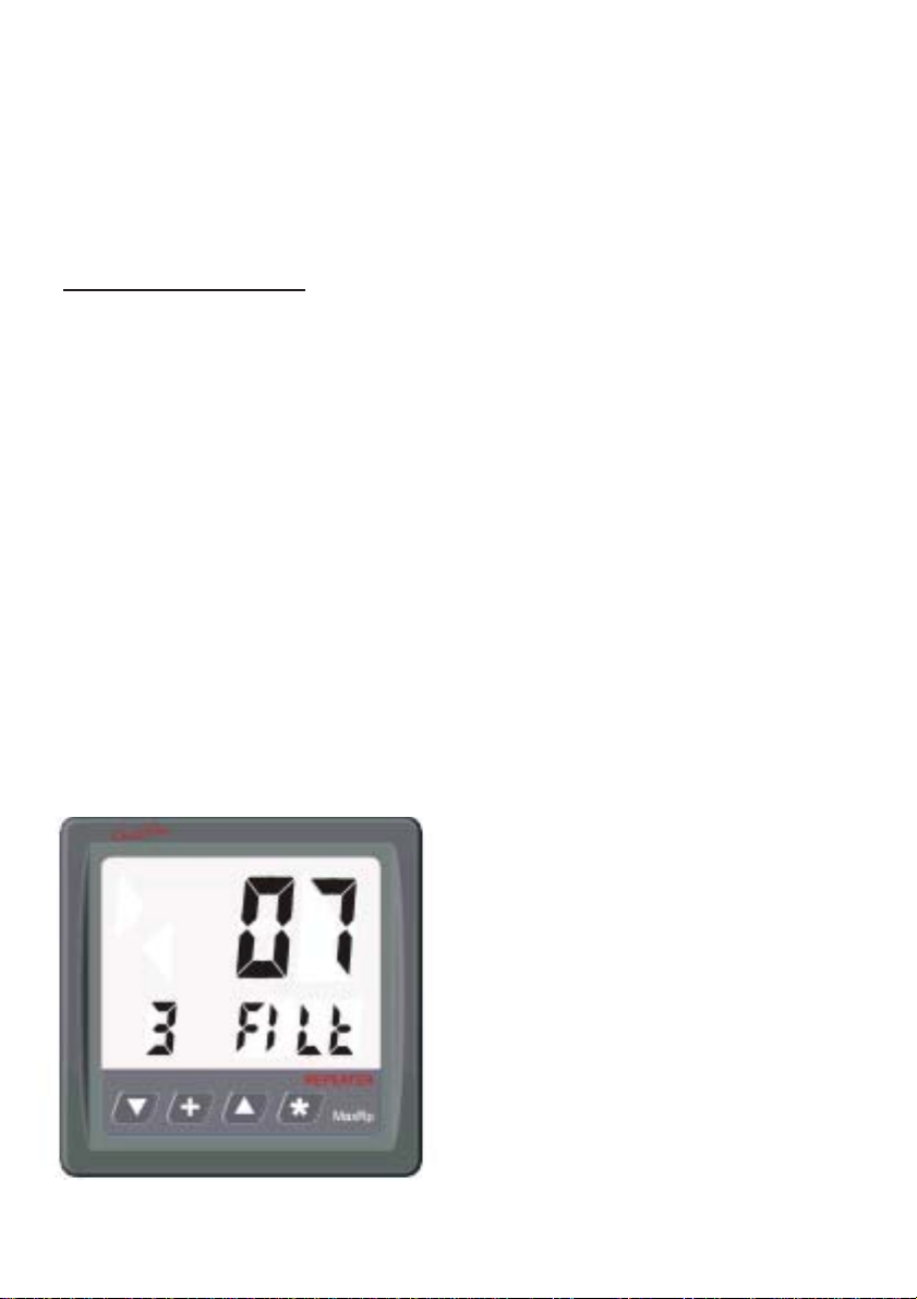
Figure 12 - Display Damping Editor
Setting the Filter Value to “7” for the
Data Source shown on digital display #3

Page15
OperationoftheWindowsSoftware
SoftwareInstallation
PlacethedistributionCDintoyourCD/DVDdriveandtheinstallprogramshould
launchautomatically. Ifitdoesnot,clickon“Start”,“Run”andtype“D:\setup.exe”
(substituteyourCD ROM drive letterfor“D” if yourCDROM is on another
drivethan“D”).
ClickOK andfollow theinstructions. Usethedefaultsunless youhave agood
reasonnot to. Iftheinstallationwassuccessful, youshouldsee:

Page16
Ifyou connectto theMaxRp110toyour PCusing aRS232 serialport thenyou
canskip thefollowing USB DriverInstallation sectionand proceeddirectly to
the “
Connecting to the MaxRp110
” section.
USBDriver Installation
Ifyou planto connecttotheMaxRp110withaUSBcableyou willfirst needto
installtheUSBdriverBEFOREyouplugthesuppliedUSBcable intoyourPC.
PlacethedistributionCDintheCDROMdriveandnavigatetothe“DRIVERS”
directory. Double click and run the program: HL-2303.EXE. After a few
secondsyouwillseethefollowingscreen:
Click “Next”and click“Finish” whenyou seethefollowingscreen:

Page17
Nowplugthe suppliedUSB/RS232cable intotheMaxRp110instrumentand
yourPCUSBport. ThefirsttimeyouplugtheUSBcableintoyourPCWindows
willdetect thenew hardwareandinstallthecorrectdriver. Dependingonyour
versionofWindowsafterafewsecondsyou willseeamessagesimilar to:
YourUSBcable isnowready to use.

Page18
Connectingto theMaxRp110
Connectthe MaxRp110to yourPC usingeither aRS232cableorthesupplied
USBcable (SeeUSB DriverInstallation FIRST). TheWindows softwarewill
lookforthe MaxRp110instrumentwhenyouwishtouploadordownloadinfor-
mationtoorfromtheinstrument.
MainScreen
TheMain Screenisdividedinto4 areas: PulldownMenus,DisplayConfigu-
rations,Data forCurrent DisplayConfiguration andan ICONSarea.
Display Configurations Area
Current Display Configuration Area
ICONS Area
Pulldown Menu Area

Page19
DisplayConfigurationsArea
The data being displayed, where it is displayed and the alarm limits for each
display iscalleda“DisplayConfiguration”. TheDisplayConfigurationsArea
shows 16 buttons numbered 1 to 16 corresponding to each of the 16 possible
displayconfigurations. Whenyouclickononeofthe16buttonsalltheinforma-
tionin the“Current DisplayConfiguration”areaandthe “ICONS”area willbe
updatedtoshowthecorrectinformationforthatDisplayConfiguration.
Inaddition tothe 16display configurationbuttons,thereare5buttonsthatwill
clearorsetalltheicons forthecurrentdisplayconfigurationorcompletelyclear
boththecurrent displayconfigurationand all theicons for thecurrent display
configuration. ThetworemainingbuttonsintheDisplayConfigurationareaare
usedto uploaddisplay configurationsto theMaxRp110anddownloaddisplay
configurationsfromtheMaxRp110(See“UploadingandDownloadingDisplay
Configurations”).
CurrentDisplayConfigurationArea
DataSources:Alltheinformationthat specifieswhat datasourcestodisplayin
eachof thethreedigitaldisplaysand thetwobarcharts,the alarmlimitsandthe
upperandlowerbarchartlimitsaredefinedintheCurrentDisplayConfiguration
area. Each of the three digital displays and two bar charts show what Data
Sourceisgoingtobeshown ontheMaxRp110LCD. Clickingthe% buttonin
oneofthese areasresults inapulldown menulisting alltheNMEA 0183Data
Sourceoptionsavailableforthatdisplayasshownbelow. Youcanscrollthrough
thelist ofup to8 differentNMEA inputsand selectthe itemyou wishto see.

Page20
Highand LowAlarmValues: TheHigh andLowalarmvaluesassignedtothe
datasource foreach ofthe fivedisplays (1,2, 3,L, R)are shownin theCurrent
Display Configuration area with a “change” box next to each. Clicking the
“Change”boxallows youtochange theHighand Low alarmlimits as shown
below. Besuretoreadthewarningsabout alarmsintheImportantNotes
andWarningssectionaboutwhichconditionswillsoundanaudiblealarm.
High and Low Limit Values for Bar Charts: Similarly the High and Low
Limitvalues ofthetwobarcharts areshown intheCurrentDisplayConfigura-
tionareaalongwith“Change”boxes. Clickingonthe“Change”boxallowsyou
tochangethe HighandLowLimitvaluesforthe twobarcharts. Thehighlimit
isthe valuethat displaysatthetopofthebar chartand thelow limitisthevalue
thatdisplays at thebottom ofthe bar chart.
AdatasourcewithavalueequaltoorgreaterthantheHighLimit
isshownhere onthe bar chart.
Adatasourcewithavalue equaltoorless thantheLowLimitis
shownhereon thebar chart.
A data source with a value between the Low Limit and High
Limitwillbedisplayedin thisareaofthebarchart.
Selectingthe Highand LowLimit valuesappropriately allowsyou toscale the
data or “zoom” into the area of interest to you. For example if you direct the
battery voltage of a 12V battery to one of the bar charts you can set the Low
Limitvalueat 11.5VandtheHighLimit valueto12.5Vprovidinganexpanded
scaleforbatteryvoltage. TheHigh andLowLimit valuesarecompletelyinde-
pendentofthehighandlowalarmlimits.
Table of contents
Other CruzPro Repeater manuals


